LTC2953 Push Button On/Off Controller with Voltage Monitoring DESCRIPTION
FEATURES ■ ■ ■ ■ ■ ■ ■ ■ ■ ■ ■ ■ ■
Wide Operating Voltage Range: 2.7V to 27V Push Button Control of System Power Low Supply Current: 14μA Power Fail Comparator Generates Warning UVLO Comparator Gracefully Latches Power Off Adjustable Supply Monitor with 200ms Reset Adjustable Power Down Timer Low Leakage EN Output (LTC2953-1) Allows DC/DC Converter Control High Voltage ⎯E⎯N Output (LTC2953-2) Allows Circuit Breaker Control Simple Interface Allows Orderly System Power Up and Power Down ±1.5% Threshold Tolerances ±10kV ESD HBM on ⎯P⎯B Input 12-Pin 3mm × 3mm DFN
The LTC®2953 is a push button On/Off controller that manages system power via a push button interface. An enable output toggles system power while an interrupt output provides debounced push button status. The interrupt output can be used in menu driven applications to request a system power down. The LTC2953 also features input and output power supply monitors. An uncommitted power fail comparator provides real time input monitor information, while a de-glitched under voltage lockout comparator gracefully initiates a system power down. The under voltage lockout comparator prevents the system from powering from a low power supply. The adjustable supply monitor input is compared against an accurate internal 0.5V reference. The reset output remains low until the supply monitor input has been in compliance for 200ms.
APPLICATIONS ■ ■ ■ ■ ■
Push Button Power Path Control Battery Power Supervisor Portable Instrumentation, PDA Blade Servers Desktop and Notebook Computers
The LTC2953 operates over a wide 2.7V to 27V input voltage range and draws only 14μA of current. Two versions of the part accommodate either positive or negative enable polarities. , LT, LTC and LTM are registered trademarks of Linear Technology Corporation. All other trademarks are the property of their respective owners.
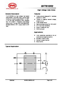
TYPICAL APPLICATION VIN
+ 8.4V
100k
2150k UVLO
23.2k
VIN
DC/DC
3.3V
SHDN
EN
499k
LTC2953-1 PFI
Push Button On/Off Control with Interrupt
VOUT
TURN ON PULSE
SHORT INTERRUPT PULSE
LONG TURN OFF PULSE
PB
100k
VM
EN
100k
TURNS ON
STAYS ON
TURNS OFF
100k
196k
100k
ON/OFF
PB
RST PFO INT KILL
GND
PDT
RST GPIO INT SYSTEM LOGIC KILL
1μF
INT INTERRUPT
INTERRUPT 2954 TD01b
2953 TA01
tPDT = 6.4 SECONDS 2953f
1
LTC2953 ABSOLUTE MAXIMUM RATINGS
PIN CONFIGURATION
(Note 1)
Supply Voltage (VIN) .................................. –0.3V to 33V Input Voltages ⎯P⎯B, ⎯P⎯F⎯I, UVLO........................................... –6V to 33V VM ......................................................... –0.3V to 20V ⎯K⎯I⎯L⎯L ....................................................... –0.3V to 10V PDT....................................................... –0.3V to 2.7V Output Voltages EN/⎯E⎯N, ⎯P⎯F⎯O ............................................ –0.3V to 50V ⎯R⎯S⎯T, ⎯I⎯N⎯T ................................................ –0.3V to 10V Operating Temperature Range LTC2953C ................................................ 0°C to 70°C LTC2953I ............................................. –40°C to 85°C Storage Temperature Range................... –65°C to 125°C
TOP VIEW GND
1
12 INT
VM
2
11 EN/EN
KILL
3
PDT
4
PB
5
8 PFI
VIN
6
7 UVLO
10 RST
13
9 PFO
DD PACKAGE 12-LEAD (3mm ´ 3mm) PLASTIC DFN TJMAX = 125°C, θJA = 43°C/W EXPOSED PAD (PIN 13) PCB GROUND CONNECTION OPTIONAL
ORDER INFORMATION LEAD FREE FINISH
TAPE AND REEL
PART MARKING*
PACKAGE DESCRIPTION
TEMPERATURE RANGE
LTC2953CDD-1#PBF LTC2953CDD-2#PBF LTC2953IDD-1#PBF LTC2953IDD-2#PBF
LTC2953CDD-1#TRPBF LTC2953CDD-2#TRPBF LTC2953IDD-1#TRPBF LTC2953IDD-2#TRPBF
LCWT LCQT LCWT LCQT
12-Lead (3mm × 3mm) Plastic DFN 12-Lead (3mm × 3mm) Plastic DFN 12-Lead (3mm × 3mm) Plastic DFN 12-Lead (3mm × 3mm) Plastic DFN
0°C to 70°C 0°C to 70°C –40°C to 85°C –40°C to 85°C
Consult LTC Marketing for parts specified with wider operating temperature ranges. *The temperature grade is identified by a label on the shipping container. Consult LTC Marketing for information on non-standard lead based finish parts. For more information on lead free part marking, go to: http://www.linear.com/leadfree/ For more information on tape and reel specifications, go to: http://www.linear.com/tapeandreel/
ELECTRICAL CHARACTERISTICS
The ● denotes the specifications which apply over the full operating temperature range, otherwise specifications are at TA = 25°C. VIN = 2.7V to 27V, unless otherwise noted (Note 2). SYMBOL
PARAMETER
CONDITIONS
MIN
Supply Voltage Range
Steady State Operation
●
TYP
MAX
UNITS
Supply Pin (VIN) VIN
2.7
IIN
VIN Supply Current
VIN = 2.7V to 27V
●
VUVL
VIN Undervoltage Lockout
VIN Falling
●
2.2
27
V
14
26
μA
2.3
2.5
V
27
V
Push Button, Enable (⎯P⎯B, EN/⎯E⎯N) VPB(MIN, MAX)
⎯P⎯B Operating Voltage Range
Single-Ended
●
–1
IPB
⎯P⎯B Input Current
2.5V < VPB < 27V VPB = 1V VPB = 0.6V
● ● ●
–1 –3
–6 –9
±1 –12 –15
μA μA μA
VPB(VTH)
⎯P⎯B Input Threshold
⎯P⎯B Falling
●
0.6
0.8
1
V
VPB(VOC)
⎯P⎯B Open Circuit Voltage
IPB = –1μA
●
1
1.6
2
V
2953f
2
LTC2953 ELECTRICAL CHARACTERISTICS
The ● denotes the specifications which apply over the full operating temperature range, otherwise specifications are at TA = 25°C. VIN = 2.7V to 27V, unless otherwise noted (Note 2).
SYMBOL
PARAMETER
CONDITIONS
MIN
IEN(LKG)
EN/⎯E⎯N Leakage Current
VEN/ ⎯E⎯N = 1V, Sink Current Off VEN/ ⎯E⎯N = 40V, Sink Current Off
● ●
VEN(VOL)
EN/⎯E⎯N Voltage Output Low
IEN/ ⎯E⎯N = 500μA
●
tEN, Lock Out
EN/⎯E⎯N Lock Out Time (Note 3)
Enable Released → Enable Asserted
●
TYP
MAX
UNITS
±0.1 ±1
μA μA
0.11
0.4
V
52
64
82
ms
On/Off Timing Pins (⎯P⎯B, UVLO, PDT, ⎯I⎯N⎯T) tDB, ON
Turn On Debounce Time
⎯P⎯B Falling → Enable Asserted
●
26
32
41
ms
IPDT(PU)
PDT Pull Up Current
VPDT = 0V
●
–2.4
–3
–3.6
μA
IPDT(PD)
PDT Pull Down Current
VPDT = 1.3V
●
2.4
3
3.6
μA
tDB, OFF
Turn Off Interrupt Debounce Time
⎯P⎯B, UVLO Falling → ⎯I⎯N⎯T Falling
●
26
32
41
ms
tPD, Min
Internal ⎯P⎯B Power Down Delay Time (Note 4)
⎯P⎯B, UVLO Falling → Enable Released PDT Open
●
52
64
82
ms
tPDT
Additional Adjustable ⎯P⎯B Power Down Delay Time
CPDT = 1500pF
●
9
11.5
13.5
ms
tINT, Min
Minimum ⎯I⎯N⎯T Pulse Width
⎯I⎯N⎯T Asserted → ⎯I⎯N⎯T Released
●
26
32
41
ms
tINT, Max
Maximum ⎯I⎯N⎯T Pulse Width
CPDT = 1500pF, ⎯I⎯N⎯T Asserted → ⎯I⎯N⎯T Released
●
35
43.5
54.5
ms
⎯K⎯I⎯L⎯L Falling
●
0.57
0.6
0.63
V
●
10
30
50
mV
●
30 30
μs
650
ms
μP Handshake Pins (⎯K⎯I⎯L⎯L, ⎯I⎯N⎯T) VKILL(TH)
⎯K⎯I⎯L⎯L Input Threshold Voltage
VKILL(HYST)
⎯K⎯I⎯L⎯L Input Threshold Hysteresis
t KILL(PW)
⎯K⎯I⎯L⎯L Minimum Pulse Width
tKILL(PD)
⎯K⎯I⎯L⎯L Propagation Delay
⎯K⎯I⎯L⎯L Falling → Enable Released
●
tKILL, ON BLANK
⎯K⎯I⎯L⎯L Turn On Blanking (Note 5)
⎯K⎯I⎯L⎯L = Low, Enable Asserted → Enable Released
●
IKILL(LKG)
⎯K⎯I⎯L⎯L Leakage Current
VKILL = 0.6V
●
±0.1
μA
IINT(LKG)
⎯I⎯N⎯T Leakage Current
VINT = 3V
●
±0.1
μA
VINT(VOL)
⎯I⎯N⎯T Output Voltage Low
IINT = 3mA
●
0.11
0.4
V
400
μs 512
Power Fail and Voltage Monitor Pins (⎯P⎯F⎯I, ⎯P⎯F⎯O, UVLO, VM, ⎯R⎯S⎯T) VPFI(TH)
⎯P⎯F⎯I Input Threshold Voltage
Falling
●
492
500
508
mV
VUVLO(TH)
UVLO Input Threshold Voltage
Falling
●
492
500
508
mV
VM(TH)
Adjustable Reset Threshold
Falling/Rising
●
492
500
508
mV
ΔVTH
⎯P⎯F⎯I-UVLO Threshold Mismatch
●
–5
0
5
mV
VPFI(HYST)
⎯P⎯F⎯I Input Hysteresis
●
2
4
10
mV
VUVLO(HYST)
UVLO Input Hysteresis
●
30
50
70
mV
VPFO(VOL)
⎯P⎯F⎯O Output Voltage Low
IPFO = 500μA
●
0.11
0.4
V
VRST(VOL)
⎯R⎯S⎯T Output Voltage Low
I = 3mA
●
0.11
0.4
V
2953f
3
LTC2953 ELECTRICAL CHARACTERISTICS
The ● denotes the specifications which apply over the full operating temperature range, otherwise specifications are at TA = 25°C. VIN = 2.7V to 27V, unless otherwise noted (Note 2).
SYMBOL
PARAMETER
CONDITIONS
IPFI(LKG)
⎯P⎯F⎯I Leakage Current
VPFI = 0.5V VPFI = 27V
IPFO(LKG)
⎯P⎯FO Leakage Current
IUVLO(LKG)
MIN
TYP
MAX
UNITS
●
2
±10 ±1
nA μA
VPFO = 1V VPFO = 40V
●
2
±10 ±1
nA μA
UVLO Leakage Current
VUVLO = 0.5V VUVLO = 27V
●
2
±10 ±1
nA μA
IVM(LKG)
VM Input Leakage Current
VM = 0.5V
●
2
±10
nA
IRST(LKG)
⎯R⎯S⎯T Output Leakage Current
VRST = 3V
●
±0.1
μA
tPFI
⎯P⎯F⎯I Delay to ⎯P⎯F⎯O
100
200
μs
tRST
Reset Timeout Period
200
260
ms
tuv
VM Under Voltage Detect to ⎯R⎯S⎯T
VM Less Than VM(TH) By More Than 1%
Note 1: Stresses beyond those listed under Absolute Maximum Ratings may cause permanent damage to the device. Exposure to any Absolute Maximum Rating condition for extended periods may affect device reliability and lifetime. Note 2: All currents into pins are positive; all voltages are referenced to GND unless otherwise noted. Note 3: The Enable Lock Out time is designed to allow an application to properly power down such that the next power up sequence starts from a consistent powered down configuration. ⎯P⎯B is ignored during this lock out time. This time delay does not include tDB, ON.
●
40
●
140
250
μs
Note 4: To manually force a release of the EN/⎯E⎯N pin, either ⎯P⎯B or UVLO must be held low for at least tPD, Min (internal default power down timer) + tPDT (adjustable by placing external capacitor at PDT pin). Note 5: The ⎯K⎯I⎯L⎯L turn on blanking timer period (tKILL, ON BLANK) is the waiting period immediately after enable output is asserted. This blanking time allows sufficient time for the DC/DC converter and the μP to perform power up tasks. The ⎯K⎯I⎯L⎯L, ⎯P⎯B and UVLO inputs are ignored during this period. If ⎯K⎯I⎯L⎯L remains low at the end of this blanking period, the enable output is released, thus turning off system power.
2953f
4
LTC2953 TYPICAL PERFORMANCE CHARACTERISTICS Supply Current vs Temperature
Turn On Debounce Time (tDB, ON) vs VIN
Supply Current vs Supply Voltage
20
50
20
TA = 25°C
TA = 25°C VIN = 27V 18
40
VIN = 2.7V
tDB, ON (ms)
IVIN (μA)
IVIN (μA)
VIN = 3.3V
15
16
14
30
20
10 12
5 –50
–25
0 25 50 TEMPERATURE (°C)
75
10
0
10
100
0
5
10
20 15 VIN (V)
25
30
2953 G01
35
10000
50 TA = 25°C
–3.4
TA = 25°C VIN = 3.3V
tPD,MIN + tPDT (ms)
tDB, OFF (ms)
1000
100
10 10 0
5
10
15 VIN (V)
20
25
1
30
10 100 PDT EXTERNAL CAPACITANCE (nF)
PDT Pull-Up Current vs Temperature –300
30
VIN = 3.3V
–3.0
–2.8
–2.6 –50
1000
–25
0 25 50 TEMPERATURE (°C)
75
100 2953 G06
⎯P⎯B Voltage vs External ⎯P⎯B Resistance to Ground 300
TA = 25°C VIN = 3.3V
–250
VIN = 3.3V
250
3.2
3.0
PB VOLTAGE (mV)
TA = 100°C PB CURRENT (μA)
PDT PULL-UP CURRENT (μA)
25
–3.2
⎯P⎯B Current vs ⎯P⎯B Voltage
VIN = 3.3V
–200 –150 –100
200 150 100
2.8 –50 2.6 –50
20
��� ���
2953 G04
3.4
15 VIN (V)
PDT Pull-Down Current vs Temperature
40
0
10
2953 G03
PDT PULL-DOWN CURRENT (μA)
Turn Off Interrupt Debounce Time (tDB, OFF) vs VIN
20
5
2953 G02
Forced Power Down Delay Time (tPD, MIN + tPDT) vs PDT External Capacitance
30
0
–25
0 25 50 TEMPERATURE (°C)
75
100 2953 G07
0 –10
TA = –45°C TA = 25°C
50 0 0
10 20 PB VOLTAGE (V)
30 ��� ���
0 5 10 15 20 EXTERNAL PB RESISTANCE TO GROUND (kΩ) ��� ���
2953f
5
LTC2953 TYPICAL PERFORMANCE CHARACTERISTICS ⎯E⎯N (LTC2953-2) Voltage vs VIN
EN (LTC2953-1) Voltage vs VIN 4
1.0
3
2
0.4 1
0 2
1
0
3
4
0
1
2
3
0
4
0
0.5
1.0
1.5
VIN (V)
VIN (V) ��� ���
2.0 2.5 VIN (V)
2953 G11
⎯R⎯S⎯T Voltage vs VIN
3.0
3.5
4.0
2953 G12
⎯R⎯S⎯T, ⎯I⎯N⎯T VOL vs Current Load 600
4
2
1
0.2
0
TA = 25°C PFI = 1V 100k PULL-UP FROM PFO TO VIN
3
PFO (V)
0.6
EN (V)
EN (V)
4
TA = 25°C 100k PULL-UP FROM EN TO VIN
TA = 25°C 100k PULL-UP FROM EN TO VIN
0.8
⎯P⎯F⎯O Voltage vs VIN
TA = 25°C VM = 1V 100k PULL-UP FROM RST TO VIN
TA = 25°C VIN = 3.3V
500 RST, INT VOL (mV)
RST (V)
3
2
400 300 200
1 100 0
0 0
0.5
1.0
1.5
2.0 2.5 VIN (V)
3.0
3.5
0
4.0
2953 G14
2953 G13
Threshold Voltage (VM, ⎯P⎯F⎯I, UVLO) vs Temperature 504
EN/⎯E⎯N, ⎯P⎯F⎯O VOL vs Current Load 800
VIN = 3.3V
TA = 25°C VIN = 3.3V EN/EN, PFO VOL (mV)
THRESHOLD (mV)
502
500
498
496 –50
10
2 4 6 8 RST, INT CURRENT LOAD (mA)
600
400
200
0 –25
0 25 50 TEMPERATURE (°C)
75
100 2953 G15
0
0.5 2 2.5 1 1.5 EN/EN, PFO CURRENT LOAD (mA)
3 2953 G16
2953f
6
LTC2953 PIN FUNCTIONS GND (Pin 1): Ground. VM (Pin 2): Voltage Monitor Input. Input to an accurate comparator with a 0.5V threshold. VM controls the state of the ⎯R⎯S⎯T output pin and is independent of ⎯P⎯B, ⎯P⎯F⎯I and UVLO status. A voltage below 0.5V on this pin asserts ⎯R⎯S⎯T low. Connect to GND if unused. ⎯K⎯I⎯L⎯L (Pin 3): ⎯K⎯I⎯L⎯L Input. Forcing ⎯K⎯I⎯L⎯L low releases the enable output. During system turn on, this pin is blanked by a 512ms internal timer (tKILL, ON BLANK) to allow the system to pull ⎯K⎯I⎯L⎯L high. This pin has an accurate 0.6V threshold and can be used as a power kill voltage monitor. Set the pin voltage above its threshold if unused.
of hysteresis. PFI controls the state of the ⎯P⎯F⎯O output pin and is independent of ⎯P⎯B, VM and UVLO status. Connect to GND if unused. ⎯P⎯F⎯O (Pin 9): Power Fail Output. This pin is a high voltage open drain pull-down. ⎯P⎯F⎯O pulls low when PFI is below 0.5V. Open circuit when unused. ⎯R⎯S⎯T (Pin 10): Reset Output. This pin is an open drain pull-down. Pulls low when VM input is below 0.5V and is held low for 200ms after VM input is above 0.5V. Open circuit when unused.
PDT (Pin 4): Power Down Time Input. A capacitor to ground determines the additional time (6.4 seconds/μF) that ⎯P⎯B or UVLO must be held low before releasing the EN/⎯E⎯N and ⎯I⎯N⎯T outputs. If this pin is left open, the power down delay time defaults to 64ms.
EN (LTC2953-1, Pin 11): Open Drain Enable Output. This output is intended to enable system power. EN is asserted high after a valid ⎯P⎯B turn on event (tDB, ON). EN is released low if: a) ⎯K⎯I⎯L⎯L is not driven high (by μP) within 512ms of the initial valid ⎯P⎯B power turn on event, b) ⎯K⎯I⎯L⎯L is driven ⎯ B ⎯ or UVLO is asserted and low during normal operation, c) P held low (t > tPD, Min + tPDT) during normal operation.
⎯P⎯B (Pin 5): Push Button Input. Connecting ⎯P⎯B to ground through a momentary switch provides On/Off control via the EN/⎯E⎯N and ⎯I⎯N⎯T outputs. An internal 100k pull-up resistor connects to an internal 1.9V bias voltage. The rugged ⎯P⎯B input withstands ±10kV ESD HBM and can be pulled up to 27V externally without consuming extra current. Voltages below ground will not damage the pin.
⎯E⎯N (LTC2953-2, Pin 11): Open Drain Enable Output. This output is intended to enable system power. ⎯E⎯N is asserted low after a valid ⎯P⎯B turn on event (tDB, ON). ⎯E⎯N is released high if: a) ⎯K⎯I⎯L⎯L is not driven high (by μP) within 512ms of the initial valid ⎯P⎯B power turn-on event, b) ⎯K⎯I⎯L⎯L is driven ⎯ B ⎯ or UVLO is asserted and low during normal operation, c) P held low (t > tPD, Min + tPDT) during normal operation.
VIN (Pin 6): Power Supply Input: 2.7V to 27V.
I⎯ ⎯N⎯T (Pin 12): Open Drain Interrupt Output. After a turn off event is detected (tDB, OFF) from ⎯P⎯B or UVLO, the LTC2953 interrupts the system (μP) by asserting ⎯I⎯N⎯T low. The μP would perform power down and housekeeping tasks and then assert the ⎯K⎯I⎯L⎯L pin low, thus releasing the enable output. The ⎯I⎯N⎯T pulse width is a minimum of 32ms and stays low as long as ⎯P⎯B is asserted. If ⎯P⎯B is asserted for longer than tPD, Min + tPDT, however, the ⎯I⎯N⎯T and EN/⎯E⎯N outputs are immediately released. Open circuit when unused.
UVLO (Pin 7): UVLO Comparator Input. When UVLO drops below its falling threshold (0.5V) for more than 32ms, the LTC2953 asserts ⎯I⎯N⎯T low, thereby requesting a system power down. If UVLO remains below its falling threshold (0.5V) for longer than the adjustable power down delay, the enable output is released. Additionally, UVLO provides a ⎯P⎯B lock out feature that prevents the user from asserting the enable output when UVLO falls below its threshold. Connect to VIN if unused. PFI (Pin 8): Power Fail Comparator Input. Input to an accurate comparator with a 0.5V falling threshold and 4mV
Exposed Pad (Pin 13): Exposed Pad may be left open or connected to ground.
2953f
7
LTC2953 BLOCK DIAGRAM VIN 2.7V TO 27V REGULATOR 1.5k
2.4V
34V ZENER
– +
+
0.5V VM
HV
–
HV
PFI
0.5V
PFO
200 ms RST DELAY
RST
HV
2.4V
EN (–1) EN (–2)
100k
PB
HV
KILL DEBOUNCE AND 10μs FILTER LOGIC
0.8V
UVLO
0.5V
0.6V INT HV
– +
DEBOUNCE AND 10μs FILTER
OSCILLATOR GND HV INDICATES A HIGH VOLTAGE PIN 2953 BD
PDT
2953f
8
LTC2953 TIMING DIAGRAMS PB, UVLO AND KILL IGNORED
PB tDB, ON
tKILL, ON BLANK
EN (LTC2953-1)
KILL
DO NOT CARE
SYSTEM SETS KILL HIGH
2953 TD01
Figure 1. Power On Timing (UVLO > 0.55V)
PB AND UVLO IGNORED
PB tDB, OFF
t < tPDT
PDT tPD, Min INT tINT, Min UVLO
EN (LTC2953-1)
UVLO IGNORED
ENABLE DOES NOT SWITCH LOW 2953 TD02
Figure 2. ⎯P⎯B Interrupt Pulse: ⎯P⎯B Low for tDB,OFF < t < (tPD, Min + tPDT) (Enable Remains Active)
2953f
9
LTC2953 TIMING DIAGRAMS PB AND UVLO IGNORED
UVLO tDB, OFF
t < tPDT
PDT tPD, Min INT tINT, Min
PB
EN (LTC2953-1)
PB IGNORED
ENABLE DOES NOT SWITCH LOW 2953 TD03
Figure 3. UVLO Interrupt Pulse: UVLO Low for tDB,OFF < t < (tPD, Min + tPDT) (Enable Remains Active)
PB IGNORED
PB tDB, OFF
16 CYCLES PDT tPD, Min
tPDT
INT tINT, Max EN (LTC2953-1)
UVLO
UVLO IGNORED 2953 TD04
Figure 4. Push Button Power Down Timing: ⎯P⎯B Pressed and Held Low for t > (tPD, Min + tPDT)
2953f
10
LTC2953 TIMING DIAGRAMS UVLO IGNORED
UVLO
tDB, OFF 16 CYCLES PDT tPD, Min
tPDT
INT tINT, Max EN (LTC2953-1)
PB
PB IGNORED 2953 TD05
Figure 5. UVLO Power Down Timing: UVLO Low for t > (tPD, Min + tPDT)
0.5V
0.5V
0.5V
VM
0.504V
PFI
tUV
tRST
tPFI
RST
tPFI
PFO 2953 TD06
2953 TD07
Figure 6. Voltage Monitor Reset Timing
Figure 7. Power Fail Comparator Timing
0.6V
tKILL(PW)
0.63V
KILL
EN (LTC2953-1)
tKILL(PD) 2953 TD08
Figure 8. ⎯K⎯I⎯L⎯L Minimum Pulse Width and Propagation Delay
2953f
11
LTC2953 OPERATION The LTC2953 is a push button On/Off controller with dual function input and output supply monitors. The part contains all the circuitry needed to debounce a push button input and provides a simple μP handshake protocol for reliable toggling of system power. The LTC2953 operates over a wide 2.7V to 27V input voltage range and draws only 14μA of current. The LTC2953 features dual function supply monitoring: a power fail comparator generates an early warning and an under voltage lock-out comparator initiates a controlled system power down. Push Button Controller The push button input controls the enable and interrupt outputs. The enable output toggles system power while the interrupt output provides debounced push button status. The interrupt output can be used in menu driven applications to request a system power down. A power kill input allows a microprocessor or other logic to release the enable output, thus immediately powering down the system. To assert the enable output (turn on system power), press the push button (⎯P⎯B) input and hold for at least 32ms. See Figure 1. Once system power has been enabled, a user can request a system power down by again pressing the push button for at least 32ms and releasing it before the PDT timer counts 16 cycles. The LTC2953 then asserts the interrupt output and the μP subsequently sets the ⎯K⎯I⎯L⎯L input low to turn off system power. Note that the UVLO input can also assert the interrupt output. See Figure 2 and Figure 3 and Dual Function Supply Monitors section. In the event that the μP does not respond to the interrupt request, the user can force release of the enable output by
pressing and holding down the push button (or UVLO) until the PDT timer times out. See Figure 4 and Figure 5. Dual Function Supply Monitors An uncommitted power fail comparator provides real time supply threshold information. The power fail input (PFI) is compared against an accurate internal 0.5V reference and the comparison result is passed directly to the power fail output (⎯P⎯F⎯O) pin. The operation of the power fail comparator is de-coupled from all other functionality and is always active. See Figure 7. The under voltage lockout comparator provides the user with another method to initiate a controlled system power down. If the UVLO pin voltage falls below its falling threshold (0.5V) for longer than 32ms, the interrupt output is asserted for a minimum of 32ms. If the UVLO pin voltage remains below its threshold (0.5V) for an additional time given by the PDT external capacitor, then the enable pin is automatically released (thus powering down the system). See Figure 3 and Figure 5. This comparator also serves as an under voltage lockout. If system power is off (enable released) and UVLO < 0.5V, the UVLO comparator prevents the push button from turning on system power (asserting enable output). Voltage Supervisor with 200ms μP Reset The LTC2953 provides a single adjustable supply monitor with a nominal 200ms reset delay. When the VM input voltage drops below 0.5V, the ⎯R⎯S⎯T output is pulled low. ⎯R⎯S⎯T remains low for 200ms after the VM input has risen above 0.5V. The input 0.5V threshold has a guaranteed accuracy of ±1.5% over temperature and process. The operation of the supply monitor is de-coupled from all other functionality and is always active. See Figure 6.
2953f
12
LTC2953 APPLICATIONS INFORMATION PUSH BUTTON CONTROL
Short Pulse Interrupt
Power On Sequence To enable system power, the push button input (⎯P⎯B) must be held low continuously for 32ms (tDB, ON). Once the enable output (EN/⎯E⎯N) is asserted, the LTC2953 starts a 512ms internal timer (tKILL, ON BLANK). The ⎯K⎯I⎯L⎯L input must be driven high within this 512ms window. This blanking time represents the maximum time allowed for the system to power up and initialize the circuits driving the ⎯K⎯I⎯L⎯L input. If ⎯K⎯I⎯L⎯L remains low at the end of the blanking period, the enable output is released (see “Aborted Power On Sequence” section). Figure 9 shows a normal power on sequence.
To interrupt the μP, either ⎯P⎯B or UVLO must be low for at least 32ms (tDB, OFF). This signals the μP either that a user has pressed the push button or that the supply is running low. The μP would then perform power down and housekeeping tasks and assert ⎯K⎯I⎯L⎯L low when done. This in turn releases the enable output, thus shutting off system power. See Figure 10. Note that either ⎯P⎯B or UVLO can control the power down sequence, but not both at the same time. For example, if both ⎯P⎯B and UVLO are high and the user presses the push button, ⎯P⎯B will be active and UVLO will be ignored until ⎯P⎯B is released or the power down sequence is complete. Forced Power Off Sequence
PB, UVLO AND KILL IGNORED
PB tDB, ON
The LTC2953 provides a failsafe feature that allows a user to manually force a system power down. For cases when the μP fails to respond to the interrupt signal, the user can force a power down by pressing and holding either the push button or the UVLO inputs low.
tKILL, ON BLANK
EN (LTC2953-1)
KILL
SYSTEM SETS KILL HIGH
DO NOT CARE
2953 F09
Figure 9. Power On Timing (UVLO > 0.55V)
Note that only the push button input can enable system power. The LTC2953 provides two enable output polarities to allow DC/DC converter control (LTC2953-1) and external power PFET control (LTC2953-2). PB OR UVLO
The length of time required to release the enable output is given by a fixed internal 64ms delay (tPD, Min) plus an adjustable power down timer delay (tPDT). The adjustable delay is set by placing an external capacitor on the PDT pin. Use the following equation to calculate the capacitance for the desired extra delay. CPDT is the PDT pin external capacitor: CPDT = 1.56E-4 [μF/ms] • (tPDT – 1ms) See Figure 11.
SHORT PULSE PB OR UVLO
tDB, OFF
LONG PULSE
INT
16 CYCLES PDT
tINT, Min KILL
DO NOT CARE
SYSTEM POWER OFF
EN (LTC2953-1)
2953 F10
Figure 10. Power Off Interrupt Timing
tPD, Min
SYSTEM SETS KILL LOW
tPDT
EN (LTC2953-1) 2953 F11
Figure 11. Forced Power Off Timing with Adjustable Delay (See Figure 5 for More Details) 2953f
13
LTC2953 APPLICATIONS INFORMATION PB, UVLO AND KILL IGNORED
PB tDB, ON
EN (LTC2953-1)
KILL
SYSTEM SETS KILL LOW
KILL
tKILL, ON BLANK
TURN ON ABORTED EN (LTC2953-1)
SYSTEM POWER OFF
SYSTEM FAILS TO SET KILL HIGH
2953 F13
tKILL(PD)
2953 F12
Figure 12. Aborted Power On Sequence, ⎯K⎯I⎯L⎯L Remaining Low Aborts Power On Sequence
Figure 13. μP Turns Off System Power
Aborted Power On Sequence
Power Fail Comparator
The LTC2953 provides an internal 512ms timer to detect when a system fails to power on properly. A power on sequence begins by debouncing the ⎯P⎯B input. After the enable pin is subsequently asserted, the LTC2953 starts the 512ms blanking timer (tKILL, ON BLANK). If the ⎯K⎯I⎯L⎯L input is not driven high within this 512ms time window, the enable pin is immediately released, thus turning off system power. This failsafe feature prevents a user from turning on the device when the circuits driving the ⎯K⎯I⎯L⎯L input do not respond within 512ms after enable has been asserted. See Figure 12.
This comparator provides real time threshold information and can serve as the first warning of a decaying battery or supply. The ⎯P⎯F⎯O output is driven low when the PFI input voltage drops below its falling threshold (0.5V) and is high impedance when PFI rises above its rising threshold (0.504V). The low leakage, high voltage PFI input (10nA, maximum) allows the use of large valued external resistors, which lowers system current consumption.
μP Turns Off System Power During Normal Operation Once the system has powered on and is operating normally, the μP can turn off power by asserting the ⎯K⎯I⎯L⎯L input low. See Figure 13. DUAL FUNCTION BATTERY SUPERVISOR The LTC2953 provides two comparators for battery monitoring: an uncommitted power fail comparator and a latched low battery comparator with μP interrupt. The application shown in Figure 14 monitors a 2 cell Li-Ion battery stack.
UVLO Comparator The under voltage lockout comparator performs three functions: a) interrupts the μP when a supply glitch drives the UVLO voltage below its falling threshold (0.5V) for longer than 32ms, followed by b) forces system power off when the UVLO voltage falls below its falling threshold (0.5V) for tPD, Min + tPDT, c) locks out the enable (prevents system power on) output if UVLO voltage is below its falling threshold (0.5V) during system power on. See Figures 15A and 15B. The low leakage (10nA, maximum), high voltage UVLO input allows the use of large valued external resistors. See Figure 14.
2953f
14
LTC2953 APPLICATIONS INFORMATION INT
to the low offset architecture of the comparators, the UVLO and ⎯P⎯F⎯I thresholds can be set to as close as ±5mV apart. The trip thresholds of the circuit of Figure 14 are 6.04V and 5.40V for the power fail and low battery (UVLO) comparators, respectively.
EN
Push Button Lockout
+ 8.4V
VIN
LTC2953-1
DEBOUNCE UVLO COMPARATOR
R14 2150k UVLO
–
VTH = 5.4V
50mV R13 23.2k
0.5V
+
DEBOUNCE AND DELAY
PFI
R12 196k
PFO
–
VTH = 6.04V
The LTC2953 provides a push button lock out feature that prevents a user from turning on a system with a dead battery. The push button input is ignored when the UVLO input voltage is less than the falling threshold (0.5V). See Figure 15B.
4mV 0.5V
+
UVLO
0.5V
SUPPLY GLITCH
0.55V
tDB, OFF
POWER FAIL COMPARATOR 2953 F14
2953 F15a
INT
tINT, Min
Figure 14. Dual Function Battery Comparators Figure 15A. Supply Glitch Generates μP Interrupt
Which Input Initiated Power Down: ⎯P⎯B or UVLO? The circuit in Figure 14 determines whether a power down was initiated by a user pressing the push button or by a battery drooping too low. If both ⎯I⎯N⎯T and ⎯P⎯F⎯O outputs are low, then a low battery condition initiated a power down.
UVLO
LOW SUPPLY CONDITION tDB, OFF
INT
PFI and UVLO Thresholds The circuit depicted in Figure 14 uses one resistive divider network for both power fail and low battery comparators. The power fail comparator trips at a higher battery voltage than the low battery comparator, thus providing a battery warning before a power down sequence is initiated. Due
0.5V
tPD, Min + tPDT EN
LOW SUPPLY LOCKS OUT ENABLE 2953 F15b
Figure 15B. Low Supply Initiates System Power Down and Locks Out Enable
2953f
15
LTC2953 TYPICAL APPLICATIONS Push Button Buffer
Disconnect Input Resistive Divider To Save Power
The circuit of Figure 16 shows the power fail comparator sensing the push button input. The ⎯P⎯F⎯O output toggles each time the push button crosses 0.5V. This application provides an early warning of push button activity.
In order to prolong battery life when system power has been turned off, the LTC2953-2 power fail comparator can be used to disconnect the external battery monitor resistive divider. The circuit in Figure 18 connects ⎯P⎯F⎯I to ⎯E⎯N and ⎯P⎯F⎯O to the bottom end of the resistive divider. 8.4V
PFO 0.5V PFI
R14 1070k
+
R5 100k
R9 100k
– UVLO
PB ON/OFF
R12 110k
2953 F16
VIN
EN
PFO
PFI 0.5V
– +
Figure 16. Push Button Buffer LTC2953-2
Power Path Switching
2953 F18
The high voltage ⎯E⎯N output of the LTC2953-2 is designed to switch On/Off an external power PFET. This allows a user to connect/disconnect a power supply (or battery) to its load by toggling the ⎯P⎯B pin. Figure 17 shows the LTC2953-2 in a 12V wall adapter application. 12V
TO LOAD R5 100k PB
ON/OFF
VIN
R9 100k
EN
LTC2953-2
Figure 18. Disconnect Input Resistive Divider to Save Power
When the user presses the push button to turn on system power (⎯E⎯N low), the output of the power fail comparator asserts ⎯P⎯F⎯O low. The low battery external resistive divider is thus enabled to monitor the input supply. If the voltage on the UVLO input falls to less than 0.5V, a system power down sequence is initiated. Note that the IR drop across the internal NFET is typically less than 0.2mV when the UVLO pin voltage is 0.5V. Once system power has been turned off (⎯E⎯N high), the external resistive divider is disconnected and thus consumes zero DC current.
2953 F17
Figure 17. Power Path Switching
2953f
16
LTC2953 TYPICAL APPLICATIONS Push Button Controlled μP Reset
Push Button Controlled Supply Sequencing
The circuit of Figure 19 can be used to keep a μP in reset for 200ms after the push button has enabled system power. After system power has stabilized, the voltage monitor input continues to monitor the supply at the load end.
The circuit in Figure 20 uses the LTC2953-2 to sequence 3 supply rails. Power on sequencing begins by pressing the push button for 32ms. This asserts the ⎯E⎯N output low, which turns on the V1 supply. 200ms after V1 reaches 80% of its final value (2.66V), the V2 supply is enabled. When the V2 DC voltage reaches 80% of its final value (2V), the V3 supply is enabled. Note that there is no internal delay from the ⎯P⎯F⎯I input to the ⎯P⎯F⎯O output and so V3 is enabled at the same time V2 rises above 2V.
TO LOAD 3.3V R5 100k VIN PB
R9 100k R3 499k
EN
A power down supply sequence begins when any of these inputs is asserted: ⎯P⎯B , UVLO or ⎯K⎯I⎯L⎯L . When ⎯E⎯N pulls up to VIN, V1 disconnects first. When V1 decays to 2.66V, V2 is immediately disabled (there is no 200ms delay from VM to ⎯R⎯S⎯T during power down). When V2 decays to 2V, V3 is immediately disabled. See Figure 21 timing diagram.
VM LTC2953-2
R2 100k
ON/OFF
R11 510k
RST 2953 F19
PB
PB
0.5V
VM
POWER ON
POWER OFF
200ms 32ms RST EN
Figure 19. Push Button Controlled μP Reset
80%
80% V1 3.3V
3.3V R5 100k VIN LTC2953-2
200ms
R9 100k
V2
80% 80%
R3 866k
EN VM
PB
V1
VTH = 2.66V
ON/OFF
R2 200k
V3 2953 F21
Figure 21. Push Button Controlled Supply Sequence Timing
VIN DC/DC #1 SHDN VOUT
RST VTH = 2.01V
R15 604k
V2 2.5V
PFI R16 200k
VIN DC/DC #2 PFO
SHDN VOUT
V3 1.8V
2953 F20
Figure 20. Push Button Controlled Supply Sequencing 2953f
17
LTC2953 TYPICAL APPLICATIONS Dual Supply Monitor with μP Reset
Operation with Supply Transients over 40V
The circuit of Figure 22 monitors two supplies and provides a μP reset. When either the ⎯P⎯F⎯I or the VM input voltage falls below its threshold (0.5V), the ⎯R⎯S⎯T output is asserted low. ⎯R⎯S⎯T remains low for 200ms after both inputs rise above 0.5V. The low leakage ⎯P⎯F⎯O output allows for large valued external resistors.
The application circuit of Figure 24 operates from a 24V nominal supply, but can withstand supply transients as high as 40V.
V2
LTC2953 PFI
PFO
– V1
+ VM
The high voltage ⎯E⎯N output of the LTC2953-2 has an absolute maximum rating of 50V, which makes it suitable for driving the gate of the external power PFET. The external 30V Zener diode (Z1) and the 10k current limiting resistor (RZ) protect the VIN supply pin of the LTC2953-2. Note that under normal 24V operation, the external Zener diode does not conduct any current. The voltage drop across RZ should be kept below 1V. Z2 should have a breakdown voltage smaller than the PFET’s gate-to-source breakdown voltage.
0.5V RST
–
RST
24V NOMINAL, 40V TRANSIENTS
μP
+
0.5V
RZ 10k
30V Z1 BZX84C30
1μF 50V VIN
2953 F22
FDS4685 Si2319DS NDS9407
10V Z2 BZX84C10 R5 100k
R9 100k EN
50V ABS MAX
PB
Figure 22. Dual Supply Monitor with μP Reset
LTC2953-2 ON/OFF
Reverse Battery Protection To protect the LTC2953 from a reverse battery connection, place a 1k resistor (R8) in series with the VIN pin. See Figure 23.
2953 F24
Figure 24. Operation with 40V Supply Transients
Power Path Controller with Low Battery Detect VIN
VOUT
+ 8.4V
R8 1k
R5 910k
LT1761 SHDN
PB
VIN
EN
ON/OFF LTC2953-1
2953 F23
The application in Figure 25 uses the push button to completely disconnect the load from the battery. If the battery voltage falls below the user specified threshold, the push button is prevented from turning on system power (asserting the enable output).
Figure 23. Reverse Battery Protection Using R8
2953f
18
LTC2953 PACKAGE DESCRIPTION DD Package 12-Lead Plastic DFN (3mm × 3mm) (Reference LTC DWG # 05-08-1725 Rev A)
0.70 ±0.05
3.50 ±0.05 2.10 ±0.05
2.38 ±0.05 1.65 ±0.05 PACKAGE OUTLINE
0.25 ± 0.05 0.45 BSC 2.25 REF RECOMMENDED SOLDER PAD PITCH AND DIMENSIONS APPLY SOLDER MASK TO AREAS THAT ARE NOT SOLDERED
3.00 ±0.10 (4 SIDES)
R = 0.115 TYP 7
0.40 ± 0.10 12
2.38 ±0.10 1.65 ± 0.10 PIN 1 NOTCH R = 0.20 OR 0.25 × 45° CHAMFER
PIN 1 TOP MARK (SEE NOTE 6) 6 0.200 REF
1
0.23 ± 0.05 0.45 BSC
0.75 ±0.05 2.25 REF
(DD12) DFN 0106 REV A
0.00 – 0.05 BOTTOM VIEW—EXPOSED PAD NOTE: 1. DRAWING IS NOT A JEDEC PACKAGE OUTLINE 2. DRAWING NOT TO SCALE 3. ALL DIMENSIONS ARE IN MILLIMETERS 4. DIMENSIONS OF EXPOSED PAD ON BOTTOM OF PACKAGE DO NOT INCLUDE MOLD FLASH. MOLD FLASH, IF PRESENT, SHALL NOT EXCEED 0.15mm ON ANY SIDE 5. EXPOSED PAD AND TIE BARS SHALL BE SOLDER PLATED 6. SHADED AREA IS ONLY A REFERENCE FOR PIN 1 LOCATION ON THE TOP AND BOTTOM OF PACKAGE
2953f
Information furnished by Linear Technology Corporation is believed to be accurate and reliable. However, no responsibility is assumed for its use. Linear Technology Corporation makes no representation that the interconnection of its circuits as described herein will not infringe on existing patent rights.
19
LTC2953 TYPICAL APPLICATION FDN360P VIN
+ 8.4V
R14 2150k
R5 100k UVLO
R13 23.2k
VIN
R3 499k
LTC2953-2 PFI
R2 100k
PB GND
PDT
3.3V
R11 100k
VM
RST PFO INT KILL
DC/DC SHDN
EN
R12 196k
ON/OFF
R9 100k
VOUT
R10 100k R1 100k RST PFO INT SYSTEM LOGIC KILL 2953 F25
1μF tPDT = 6.4 SECONDS
Figure 25. PowerPath Controller with Low Battery Detect
RELATED PARTS PART NUMBER
DESCRIPTION
COMMENTS
LTC2900
Programmable Quad Supply Monitor
Adjustable Reset, 10-Lead MSOP and 3mm × 3mm DFN Packages
LTC2904/LTC2905
Pin-Programmable Dual Supply Monitors
Adjustable Reset and Tolerance, 8-Lead SOT-23 and 3mm × 2mm DFN Packages
LTC2909
Precision Tripple/Dual Input UV, OV and Negative 6.5V Shunt Regulator for High Voltage Operation Voltage Monitor
LTC2912
Single UV/OV Monitor
3mm × 2mm DFN, 8-Pin ThinSOT Packages
LTC2950/LTC2951
Push Button On/Off Controllers
High Voltage, Low Power Push Button Controller
LTC2952
Push Button Power Path Controller with Supervisor
Automatic Low Loss Switchover Between DC Sources
LTC2954
Push Button On/Off Controller with μP Interrupt
Allow Controlled Software System Shutdown
LTC4055
USB Power Controller and Li-Ion Charger
Automatic Switchover, Charges 1-Cell Li-Ion Batteries
LTC4411
2.6A Low Loss Ideal Diode in ThinSOT
No External MOSFET, Automatic Switching Between DC Sources
LTC4412HV
PowerPath Controller in ThinSOT
Efficient Diode-ORing, Automatic Switching Between DC Sources, 3V to 36V
2953f
20 Linear Technology Corporation
LT 0607 • PRINTED IN USA
1630 McCarthy Blvd., Milpitas, CA 95035-7417 (408) 432-1900 ● FAX: (408) 434-0507
●
www.linear.com
© LINEAR TECHNOLOGY CORPORATION 2007