LTC4358 5A Ideal Diode FEATURES
DESCRIPTION
n
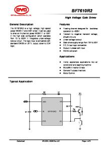
The LTC®4358 is a 5A ideal diode that uses an internal 20mΩ N-channel MOSFET to replace a Schottky diode when used in diode-OR and high current diode applications. The LTC4358 reduces power consumption, heat dissipation, and PC board area.
n n n n n n
Replaces a Power Schottky Diode Internal 20mΩ N-Channel MOSFET 0.5μs Turn-Off Time Limits Peak Fault Current Operating Voltage Range: 9V to 26.5V Smooth Switchover without Oscillation No Reverse DC Current Available in 14-Pin (4mm × 3mm) DFN and 16-Lead TSSOP Packages
The LTC4358 easily ORs power supplies together to increase total system reliability. In diode-OR applications, the LTC4358 regulates the forward voltage drop across the internal MOSFET to ensure smooth current transfer from one path to the other without oscillation. If the power source fails or is shorted, a fast turnoff minimizes reverse current transients.
APPLICATIONS n n n n
N+1 Redundant Power Supplies High Availability Systems Telecom Infrastructure Automotive Systems
L, LT, LTC and LTM are registered trademarks of Linear Technology Corporation. All other trademarks are the property of their respective owners.
TYPICAL APPLICATION 12V, 5A Diode-OR
Power Dissipation vs Load Current 3.0
IN
DRAIN
2.5
OUT LTC4358
VDD VOUT TO 5A LOAD
GND
POWER DISSIPATION (W)
VINA = 12V
DIODE (B530C) 2.0 1.5 POWER SAVED 1.0 0.5
VINB = 12V
IN
DRAIN
FET (LTC4358) 0
OUT LTC4358
VDD
0
2
4 CURRENT (A)
6
8 4358 TA01b
GND 4358 TA01
4358fa
1
LTC4358 ABSOLUTE MAXIMUM RATINGS
(Notes 1, 2)
Supply Voltages IN, OUT, VDD, DRAIN Voltage ................. –0.3V to 28V Output Voltage GATE (Note 3) .......................... VIN – 0.2V to VIN + 6V Operating Ambient Temperature Range LTC4358C ................................................ 0°C to 70°C LTC4358I.............................................. –40°C to 85°C
Storage Temperature Range................... –65°C to 150°C Lead Temperature (Soldering, 10 sec) FE Package ....................................................... 300°C
PIN CONFIGURATION TOP VIEW TOP VIEW
IN
1
16 IN
IN
1
14 IN
IN
2
15 IN
IN
2
13 IN
IN
3
14 IN
IN
3
12 IN
IN
4
IN
4
GATE
5
NC
5
GATE
6
11 NC
NC
7
10 OUT
GND
8
9
15 DRAIN
11 IN 10 NC
NC
6
9 OUT
GND
7
8 VDD
DE PACKAGE 14-LEAD (4mm s 3mm) PLASTIC DFN
17 DRAIN
13 IN 12 IN
VDD
FE PACKAGE 16-LEAD PLASTIC TSSOP
TJMAX = 125°C, θJC = 4°C/W, θJA = 43°C/W
TJMAX = 125°C, θJC = 10°C/W, θJA = 38°C/W
ORDER INFORMATION LEAD FREE FINISH
TAPE AND REEL
PART MARKING*
PACKAGE DESCRIPTION
TEMPERATURE RANGE
LTC4358CDE#PBF
LTC4358CDE#TRPBF
4358
14-Lead (4mm × 3mm) Plastic DFN
0°C to 70°C
LTC4358IDE#PBF
LTC4358IDE#TRPBF
4358
14-Lead (4mm × 3mm) Plastic DFN
–40°C to 85°C
LTC4358CFE#PBF
LTC4358CFE#TRPBF
4358FE
16-Lead Plastic TSSOP
0°C to 70°C
LTC4358IFE#PBF
LTC4358IFE#TRPBF
4358FE
16-Lead Plastic TSSOP
–40°C to 85°C
Consult LTC Marketing for parts specified with wider operating temperature ranges. *Temperature grades are identified by a label on the shipping container. Consult LTC Marketing for information on non-standard lead based finish parts. For more information on lead free part marking, go to: http://www.linear.com/leadfree/ For more information on tape and reel specifications, go to: http://www.linear.com/tapeandreel/
4358fa
2
LTC4358 ELECTRICAL CHARACTERISTICS
The l denotes the specifications which apply over the full operating temperature range, otherwise specifications are at TA = 25°C. VOUT = VDD, VDD = 9V to 26.5V, unless otherwise noted. SYMBOL
PARAMETER
CONDITIONS
VDD
Operating Supply Range
l
IDD
Operating Supply Current
l
IIN
IN Pin Current
VIN = VOUT ± 1V, No Load
l
IOUT
OUT Pin Current
VIN = VOUT ± 1V, No Load
l
IDRAIN
DRAIN Pin Current
VIN = 0V, VOUT = VDD = VDRAIN = 26.5V
ΔVGATE
N-Channel Gate Drive (VGATE – VIN)
VDD, VOUT = 9V to 26.5V
l
4.5
IGATE(UP)
N-Channel Gate Pull Up Current
VGATE = VIN, VIN – VOUT = 0.1V
l
–14
–20
IGATE(DOWN)
N-Channel Gate Pull Down Current in Fault Condition
VGATE = VIN + 5V
l
1
2
tON
Turn-On Time
l
200
500
μs
tOFF
Turn-Off Time
– VIN – VOUT = –1V –| 0.1V, VDRAIN = VIN, VOUT = VDD, VGATE – VIN > 4.5V – VIN – VOUT = 55mV |– –1V, VDRAIN = VIN, VOUT = VDD, VGATE – VIN < 1V
l
300
500
ns
ΔVSD
Source-Drain Regulation Voltage (VIN – VOUT)
1mA < IIN < 100mA
l
10
25
55
mV
ΔVSD
Body Diode Forward Voltage Drop
IIN = 5A, MOSFET Off
l
0.6
0.8
1
V
RDS(ON)
Internal N-Channel MOSFET On Resistance
IIN = 5A
l
20
40
mΩ
Note 1: Stresses beyond those listed under Absolute Maximum Ratings may cause permanent damage to the device. Exposure to any Absolute Maximum Rating condition for extended periods may affect device reliability and lifetime.
MIN
TYP
9 150
MAX
UNITS
26.5
V
0.6
mA
350
450
μA
80
160
μA
5 150
μA μA
15
V
–26
μA
l
A
Note 2: All currents into pins are positive, all voltages are referenced to GND unless otherwise specified. Note 3: An internal clamp limits the GATE pin to a minimum of 6V above IN. Driving this pin to voltages beyond this clamp may damage the device.
4358fa
3
LTC4358 TYPICAL PERFORMANCE CHARACTERISTICS VDD Current (IDD vs VDD)
400
500
IN Current (IIN vs VIN)
VIN = VOUT = VDD
VIN = VOUT = VDD
400
VIN = VOUT = VDD 80
300
IOUT (μA)
300
IIN (μA)
IDD (μA)
OUT Current (IOUT vs VOUT) 100
200
200
60
40
100 20
100
0
0 0
20
10
30
0
20
10
0
30
0
VDD (V)
30
VOUT (V) 4358 G03
4358 G02
4358 G01
FET Turn-Off Time vs Final Overdrive
FET Turn-Off Time vs Initial Overdrive
MOSFET RDS(ON) vs Temperature 30
2000
400 IIN = 5A
VIN = 12V $VSD = 55mV
25 VOUT = VDD = 9V
VFINAL
1500
300
15 VOUT = VDD = 26.5V
tPD (ns)
20 tPD (ns)
RDS(ON) (mΩ)
20
10
VIN (V)
200 VIN = 12V $VSD = VINITIAL
10
1000
-1V 500
100 5 0 -50
-25
0
25
50
75
100
125
TEMPERATURE (˚C) 4358 G04
0
0 0
0.2
0.4
0.6
0.8
1
0
-0.2
-0.4
-0.6
-0.8
-1
VFINAL (V)
VINITIAL (V) 4358 G05
4358 G06
4358fa
4
LTC4358 PIN FUNCTIONS
(DE/FE PACKAGES)
DRAIN: The exposed pad is the drain of the internal N-channel MOSFET. This pin must be connected to OUT (Pin 9/Pin 10). GATE: Gate Drive Output. If reverse current flows, a fast pulldown circuit quickly connects the GATE pin to the IN pin, turning off the MOSFET. Leave open if unused. GND: Device Ground. IN: Input Voltage and Fast Pulldown Return. IN is the anode of the ideal diode. The voltage sensed at this pin is used to control the source-drain voltage drop across the internal MOSFET. If reverse current starts to flow, a fast pulldown circuit quickly turns off the internal MOSFET. The fast pulldown current is returned through this pin.
NC: No Connection. Not internally connected. OUT: Output Voltage. The OUT pin is the cathode of the ideal diode and the common output when multiple LTC4358s are configured as an ideal diode-OR. The voltage sensed at this pin is used to control the source-drain voltage drop across the MOSFET. Connect this pin to the drain of the internal N-channel MOSFET (Pin 15/Pin 17). VDD: Positive Supply Input. The LTC4358 is powered from the VDD pin. Connect this pin to OUT either directly or through an RC hold-up circuit.
BLOCK DIAGRAM DRAIN
GATE
IN
OUT CHARGE PUMP
+
+ –
IN
–
25mV
VDD
GATE AMP
+
–
FPD COMP
+ –
25mV
GND 4358 BD
4358fa
5
LTC4358 OPERATION High availability systems often employ parallel-connected power supplies or battery feeds to achieve redundancy and enhance system reliability. ORing diodes have been a popular means of connecting these supplies at the point of load. The disadvantage of this approach is the forward voltage drop and resulting efficiency loss. This drop reduces the available supply voltage and dissipates significant power. Using an N-channel MOSFET to replace a Schottky diode reduces the power dissipation and eliminates the need for costly heat sinks or large thermal layouts in high power applications. The LTC4358 is a single positive voltage ideal diode controller that drives an internal N-channel MOSFET as a pass transistor to replace a Schottky diode. The IN and DRAIN pins form the anode and cathode of the ideal diode. The input supply is connected to the IN pins, while the DRAIN pin serves as the output. The OUT pin is connected directly to DRAIN and VDD. VDD is the supply for the LTC4358 and is derived from the output either directly or through an RC hold-up circuit.
At power-up, the load current initially flows through the body diode of the internal MOSFET. The internal MOSFET turns on and the amplifier tries to regulate the voltage drop across the IN and OUT connections to 25mV. If the load current causes more than 25mV of drop, the MOSFET is driven fully on and the voltage drop is equal to RDS(ON) • ILOAD. If the load current is reduced causing the forward drop to fall below 25mV, the internal MOSFET is driven lower by a weak pull-down in an attempt to maintain the drop at 25mV. If the load current reverses the MOSFET is turned off with a strong pull-down. In the event of a power supply failure, such as if the supply that is conducting most or all of the current is shorted to ground, reverse current temporarily flows through the LTC4358 ideal diode that is on. This current is sourced from any load capacitance and from the other supplies. The ideal diode is turned off within 500ns, preventing reverse current from slewing up to a damaging level and minimizing any disturbance on the output.
4358fa
6
LTC4358 APPLICATIONS INFORMATION ORing Two Supply Outputs Where LTC4358s are used to combine the outputs of two supplies, the power supply with the highest output voltage sources most or all of the current. If this supply’s output is quickly shorted to ground while delivering load current, the current temporarily reverses and flows backwards through the LTC4358. When reverse current flows the LTC4358 ideal diode is quickly turned off. If the other initially lower supply was not delivering load current at the time of the fault, the output falls until the LTC4358 body diode conducts. Meanwhile, the internal amplifier turns on the MOSFET until the forward drop is reduced to 25mV. If instead this supply was delivering load current at the time of the fault, its ORing MOSFET was already driven at least partially on, and will be driven harder in an effort to maintain a drop of 25mV.
VINA = 12V
IN
DRAIN
RTNA
OUT LTC4358
Figure 1 combines the outputs of multiple, redundant supplies using a simple technique known as droop sharing. Load current is first taken from the highest output, with the low outputs contributing as the output voltage falls under increased loading. The 25mV regulation technique ensures smooth load sharing between outputs without oscillation. The degree of sharing depends on the 20mΩ resistance of the LTC4358 internal MOSFET, the output impedance of the supplies and their initial output voltages.
VDD
GND
VINB = 12V
IN
DRAIN
PS2
OUT
RTNB LTC4358
VDD
GND
VINC = 12V
IN
DRAIN
PS3 OUT
RTNC
Load Sharing
12V BUS
PS1
LTC4358
VDD
GND 4358 F01
Figure 1. Droop Sharing Redundant Supplies
4358fa
7
LTC4358 APPLICATIONS INFORMATION VDD Hold-Up Circuit In the event of an input short, parasitic inductance between the input supply of the LTC4358 and the load bypass capacitor may cause VDD to glitch below its minimum operating voltage. This causes the turn-off time (tOFF) to increase. To preserve the fast turn-off time, local output bypassing of 39μF or more is sufficient or a 100Ω, 0.1μF RC hold-up circuit on the VDD pin can be used as shown in Figure 2a and Figure 2b. Layout Considerations The following advice should be considered when laying out a printed circuit board for the LTC4358: The OUT pin should
be connected as closely as possible to the EXPOSED PAD (drain of the MOSFET) for good accuracy. Keep the traces to the IN and DRAIN wide and short. The PCB traces associated with the power path through the MOSFET should have low resistance. See Figure 4. The DRAIN acts as a heatsink to remove the heat from the device. For a single layer PCB with the DFN package, use Figure 5 to determine the PCB area needed for a specified maximum current and ambient temperature. If using a two sided PCB, the maximum current is increased by 10%. If the FE package is used, the maximum current is increased by 4%.
(a) VIN = 12V
IN
DRAIN
VOUT
VIN = 12V
IN
OUT
OUT LTC4358
VOUT 12V 5A
DRAIN
R1 100Ω
LTC4358
VDD
VDD
CBYPASS 39MF
GND
CLOAD
C1 0.1μF
GND
MMBD1205
4358 F03
(b) VIN = 12V
IN
DRAIN
VOUT
OUT LTC4358
VDD
GND 4358 F02
R1 1007
Figure 3. –12V Reverse Input Protection
C1 0.1MF
Figure 2. Two Methods of Protecting Against Collapse of VDD From Input Short and Stray Inductance
4358fa
8
LTC4358 APPLICATIONS INFORMATION VIN
GND
VOUT
Figure 4. DFN Layout Considerations for 1” × 1” Single Sided PCB
10
TA =
AREA (INCH2)
85oC
70oC
50oC
25oC
1
0.1 3.0
3.5
4.0
4.5
5.0
5.5
6.0
6.5
DIODE CURRENT (A) 4358 F05
Figure 5. Maximum Diode Current vs PCB Area
4358fa
9
LTC4358 PACKAGE DESCRIPTION DE Package 14-Lead Plastic DFN (4mm × 3mm) (Reference LTC DWG # 05-08-1708)
0.70 ±0.05 3.30 ±0.05
3.60 ±0.05 2.20 ±0.05
1.70 ± 0.05 PACKAGE OUTLINE 0.25 ± 0.05 0.50 BSC 3.00 REF
RECOMMENDED SOLDER PAD PITCH AND DIMENSIONS APPLY SOLDER MASK TO AREAS THAT ARE NOT SOLDERED
R = 0.115 TYP
4.00 ±0.10 (2 SIDES) R = 0.05 TYP
3.00 ±0.10 (2 SIDES)
8
0.40 ± 0.10 14
3.30 ±0.10 1.70 ± 0.10
PIN 1 NOTCH R = 0.20 OR 0.35 × 45° CHAMFER
PIN 1 TOP MARK (SEE NOTE 6)
(DE14) DFN 0806 REV B
7 0.200 REF
1 0.25 ± 0.05 0.50 BSC
0.75 ±0.05 3.00 REF 0.00 – 0.05
BOTTOM VIEW—EXPOSED PAD
NOTE: 1. DRAWING PROPOSED TO BE MADE VARIATION OF VERSION (WGED-3) IN JEDEC PACKAGE OUTLINE MO-229 2. DRAWING NOT TO SCALE 3. ALL DIMENSIONS ARE IN MILLIMETERS 4. DIMENSIONS OF EXPOSED PAD ON BOTTOM OF PACKAGE DO NOT INCLUDE MOLD FLASH. MOLD FLASH, IF PRESENT, SHALL NOT EXCEED 0.15mm ON ANY SIDE 5. EXPOSED PAD SHALL BE SOLDER PLATED 6. SHADED AREA IS ONLY A REFERENCE FOR PIN 1 LOCATION ON THE TOP AND BOTTOM OF PACKAGE
4358fa
10
LTC4358 PACKAGE DESCRIPTION FE Package 16-Lead Plastic TSSOP (4.4mm) (Reference LTC DWG # 05-08-1663)
Exposed Pad Variation BC
4.90 – 5.10* (.193 – .201)
3.58 (.141)
3.58 (.141) 16 1514 13 12 1110
6.60 ±0.10
9
2.94 (.116)
4.50 ±0.10
6.40 2.94 (.252) (.116) BSC
SEE NOTE 4
0.45 ±0.05 1.05 ±0.10 0.65 BSC 1 2 3 4 5 6 7 8
RECOMMENDED SOLDER PAD LAYOUT
4.30 – 4.50* (.169 – .177)
0.09 – 0.20 (.0035 – .0079)
0.50 – 0.75 (.020 – .030)
NOTE: 1. CONTROLLING DIMENSION: MILLIMETERS MILLIMETERS 2. DIMENSIONS ARE IN (INCHES) 3. DRAWING NOT TO SCALE
0.25 REF
1.10 (.0433) MAX 0° – 8°
0.65 (.0256) BSC
0.195 – 0.30 (.0077 – .0118) TYP
0.05 – 0.15 (.002 – .006) FE16 (BC) TSSOP 0204
4. RECOMMENDED MINIMUM PCB METAL SIZE FOR EXPOSED PAD ATTACHMENT *DIMENSIONS DO NOT INCLUDE MOLD FLASH. MOLD FLASH SHALL NOT EXCEED 0.150mm (.006") PER SIDE
4358fa
Information furnished by Linear Technology Corporation is believed to be accurate and reliable. However, no responsibility is assumed for its use. Linear Technology Corporation makes no representation that the interconnection of its circuits as described herein will not infringe on existing patent rights.
11
LTC4358 TYPICAL APPLICATION Plug-In Card Input Diode for Supply Hold-Up BACKPLANE PLUG-IN CARD CONNECTORS CONNECTOR 1
IN
12V
OUT
HOT SWAP CONTROLLER
VOUT1
100Ω
+
LTC4358 GND
CHOLDUP
VDD 0.1μF
GND
IN
OUT
HOT SWAP CONTROLLER
VOUT2
100Ω LTC4358 GND
+ CHOLDUP
VDD 0.1μF
GND 4358 TA02
PLUG-IN CARD CONNECTOR 2
RELATED PARTS PART NUMBER
DESCRIPTION
COMMENTS
LT1640AH/LT1640AL
Negative High Voltage Supplies From –10V to –80V
LT1641-1/LT1641-2
Negative High Voltage Hot Swap™ Controllers in SO-8 Positive High Voltage Hot Swap Controllers
LT4250
–48V Hot Swap Controller
Active Current Limiting, Supplies From –20V to –80V
LTC4251/LTC4251-1/ LTC4251-2 LTC4252-1/LTC4252-2/ LTC4252-1A/LTC4252-2A LTC4253
–48V Hot Swap Controllers in SOT-23
Fast Active Current Limiting, Supplies From –15V
–48V Hot Swap Controllers in MS8/MS10
LT4256 LTC4260
Positive 48V Hot Swap Controller with Open-Circuit Detect Positive High Voltage Hot Swap Controller
Fast Active Current Limiting, Supplies From –15V, Drain Accelerated Response Fast Active Current Limiting, Supplies From –15V, Drain Accelerated Response, Sequenced Power Good Outputs Foldback Current Limiting, Open-Circuit and Overcurrent Fault Output, Up to 80V Supply With I2C and ADC, Supplies from 8.5V to 80V
LTC4261
Negative High Voltage Hot Swap Controller
With I2C and 10-Bit ADC, Adjustable Inrush and Overcurrent Limits
LTC4350
Hot Swappable Load Share Controller
Output Voltage: 1.2V to 20V, Equal Load Sharing
LT4351
MOSFET Diode-OR Controller
External N-Channel MOSFETs Replace ORing Diodes, 1.2V to 20V
LTC4352
Ideal Diode Controller with Monitor
Controls N-Channel MOSFET, 0V to 18V Operation
LTC4354
Negative Voltage Diode-OR Controller and Monitor Positive Voltage Diode-OR Controller and Monitor Positive High Voltage Ideal Diode Controller
Controls Two N-Channel MOSFETs, 1μs Turn-Off, 80V Operation
LTC4355 LTC4357
–48V Hot Swap Controller with Sequencer
LTC4223-1/LTC4223-2
Dual Supply Hot Swap Controller for Advanced Mezzanine Cards and μTCA Hot Swap is a trademark of Linear Technology Corporation.
Active Current Limiting, Supplies From 9V to 80V
Controls Two N-Channel MOSFETs, 0.5μs Turn-Off, 80V Operation Controls Single N-Channel MOSFET, 0.5μs Turn-Off, 80V Operation Controls 12V Main and 3.3V Auxiliary Supplies
4358fa
12 Linear Technology Corporation
LT 0808 REV A • PRINTED IN USA
1630 McCarthy Blvd., Milpitas, CA 95035-7417 (408) 432-1900
●
FAX: (408) 434-0507 ● www.linear.com
© LINEAR TECHNOLOGY CORPORATION 2007