MIC811/812 Microprocessor Reset Circuits
General Description
Features
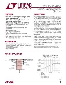
The MIC811 and MIC812 are inexpensive microprocessor supervisory circuits that monitor power supplies in microprocessor based systems.
• Precision voltage monitor for 3V, 3.3V or 5V power supplies • /RESET remains valid with VCC as low as 1V • 5μA typical supply current • 140ms minimum reset pulse width available • Manual reset input • Available in 4-pin SOT-143 package
The function of this device is to assert a reset if either the power supply drops below a designated reset threshold level or /MR is forced low. Several different reset threshold levels are available to accommodate 3V, 3.3V or 5V powered systems. The MIC811 has an active low /RESET output, while the MIC812 offers an active high RESET output. The reset output is guaranteed to remain asserted for a minimum of 140ms after VCC has risen above the designed reset threshold level. Having a push-pull output stage, the MIC811/812 does not require a pull-up resistor at the output. The MIC811/812 comes in a 4-pin SOT-143 package.
Applications • • • • •
Portable equipment Intelligent instruments Critical microprocessor power monitoring Printers/computers Controllers
If a microprocessor voltage supervisor with an open-drain output stage is needed, see MIC6315. Datasheets and support documentation are available on Micrel’s web site at: www.micrel.com.
Typical Application
Micrel Inc. • 2180 Fortune Drive • San Jose, CA 95131 • USA • tel +1 (408) 944-0800 • fax + 1 (408) 474-1000 • http://www.micrel.com
September 9, 2014
Revision 2.0
Micrel, Inc.
MIC811/812
Ordering Information Part Number Pb-Free
Marking(1)
Threshold Voltage
Operating Temp. Range
Package
MIC811LUY
KL
4.63
–40°C to +85°C
4-pin SOT-143
MIC811MUY
KM
4.38
–40°C to +85°C
4-pin SOT-143
MIC811JUY
KJ
4.00
–40°C to +85°C
4-pin SOT-143
MIC811TUY
KT
3.08
–40°C to +85°C
4-pin SOT-143
MIC811SUY
KS
2.93
–40°C to +85°C
4-pin SOT-143
MIC811RUY
KR
2.63
–40°C to +85°C
4-pin SOT-143
MIC812LUY
LL
4.63
–40°C to +85°C
4-pin SOT-143
MIC812MUY
LM
4.38
–40°C to +85°C
4-pin SOT-143
MIC812JUY
LJ
4.00
–40°C to +85°C
4-pin SOT-143
MIC812TUY
LT
3.08
–40°C to +85°C
4-pin SOT-143
MIC812SUY
LS
2.93
–40°C to +85°C
4-pin SOT-143
MIC812RUY
LR
2.63
–40°C to +85°C
4-pin SOT-143
Note: 1. “_” underbar symbol not to scale
Pin Configuration
MIC811 4-Pin SOT-143 (U)
MIC812 4-Pin SOT-143 (U)
Pin Description MIC811
MIC812
Pin Name
Pin Name
1
1
GND
2
N/A
/RESET
/RESET goes low if VCC falls below the reset threshold and remains asserted for one reset timeout period (140ms min.) after VCC exceeds the reset threshold.
N/A
2
RESET
RESET goes high if VCC falls below the reset threshold and remains asserted for one reset timeout period (140ms min.) after VCC exceeds the reset threshold.
IC Ground Pin.
3
3
/MR
Manual Reset Input. A logic low on /MR will force a reset. The reset will remain asserted as long as /MR is held low and for one reset timeout period (140ms min.) after /MR goes high. This input can be shorted to ground via a switch or driven from CMOS or TTL logic. Float if unused.
4
4
VCC
Power Supply Input.
September 9, 2014
2
Revision 2.0
Micrel, Inc.
MIC811/812
Absolute Maximum Ratings(2)
Operating Ratings(3)
Terminal Voltage (VCC) ................................ -0.3V to +6.0V Input Current (VCC, /MR)............................................ 20mA Output Current (/RESET, RESET) .............................. 20mA Lead Temperature (soldering, 10s) ............................ 300°C Storage Temperature (Ts)............................... 5°C to 150°C Rate of Rise (VCC) ................................................. 100V/µs ESD Rating(4) .................................................................. 3kV
Operating Temperature Range MIC811 ................................................. –40°C to +85°C MIC812 ................................................. –40°C to +85°C Power Dissipation (TA = +70°C) ............................... 320mW Thermal Resistance SOT-143 (θJA) .................................................. 265°C/W
Electrical Characteristics(5) For typical values, VCC = 5V for MIC8_L/M/J, VCC = 3.3V for MIC8_S/T, VCC = 3V for MIC8_R; TA = 25°C, bold values indicate – 40°C to ≤ TA ≤ +85°C; unless noted. Symbol
Parameter
Condition
VCC
Operating Voltage Range
TA = –40°C to 85°C
IVCC
VTH
Supply Current
Reset Voltage Threshold
tRST
Reset Timeout Period
VOH
/RESET Output Voltage
VOL
/RESET Output Voltage
VOH
RESET Output Voltage
VOL
RESET Output Voltage
Min
Typ
1
Max
Units
5.5
V
MIC811L/M/J, MIC812L/M/J: VCC = 5.0V, no load
5
15
µA
MIC811S/T, MIC812S/T: VCC = 3.3V, no load
5
10
µA
MIC811R, MIC812R: VCC = 3.0V, no load
5
10
µA
MIC811L, MIC812L
4.50
4.63
4.75
V
MIC811M, MIC812M
4.25
4.38
4.50
V
MIC811J, MIC812J
3.89
4.00
4.10
V
MIC811T, MIC812T
3.00
3.08
3.15
V
MIC811S, MIC812S
2.85
2.93
3.00
V
MIC811R, MIC812R
2.55
2.63
2.70
V
140
240
560
ms
ISOURCE = 800µA, MIC811L/M/J
VCC–1.5V
V
ISOURCE = 500µA, MIC811R/S/T
0.8xVCC
V
VCC = VTH min., ISINK = 3.2mA, MIC811L/M/J
0.4
V
VCC = VTH min., ISINK = 1.2mA, MIC811R/S/T
0.3
V
VCC >1V, ISINK = 50µA, TA = –40°C to +85°C
0.3
V
1.8V VTH max., MIC81-L/M/J MIC81_R/S/T 10
/MR Pull-Up Resistance /MR Glitch Immunity
20 100
0.8
V
0.25xVCC
V
30
kΩ ns
Timing Diagram
Reset Timing Diagram
Functional Diagram
September 9, 2014
4
Revision 2.0
Micrel, Inc.
MIC811/812 /RESET Valid at Low Voltage A resistor can be added from the /RESET pin to ground to ensure the /RESET output remains low with VCC down to 0V. A 100kΩ resistor connected from the /RESET to ground is recommended. The size of the resistor should be large enough not to load the output excessively and small enough to pull-down any stray leakage currents.
Application Information Microprocessor Reset The /RESET (or RESET) pin is asserted whenever VCC falls below the reset threshold voltage. The /RESET pin remains asserted for a period of 140ms after VCC has risen above the reset threshold voltage. The reset function ensures that the microprocessor is properly reset and powers up in a known condition after a power failure. /RESET will remain valid with VCC as low as 1V. VCC Transients The MIC811/812 are relatively immune to negative-going VCC glitches below the reset threshold. Typically, a negative-going transient 125mV below the reset threshold with a duration of 20μs or less will not cause a reset. Interfacing to Bidirectional Reset Pins The MIC811/812 can interface with µPs with bidirectional reset pins by connecting a 4.7kΩ resistor in series with the MIC811/812 output and the µP reset pin.
September 9, 2014
Reset Valid to VCC = 0V
5
Revision 2.0
Micrel, Inc.
MIC811/812
Package Information
4-Pin SOT-143 (U)
September 9, 2014
6
Revision 2.0
Micrel, Inc.
MIC811/812
MICREL, INC. 2180 FORTUNE DRIVE SAN JOSE, CA 95131 USA TEL +1 (408) 944-0800 FAX +1 (408) 474-1000 WEB http://www.micrel.com Micrel, Inc. is a leading global manufacturer of IC solutions for the worldwide high performance linear and power, LAN, and timing & communications markets. The Company’s products include advanced mixed-signal, analog & power semiconductors; highperformance communication, clock management, MEMs-based clock oscillators & crystal-less clock generators, Ethernet switches, and physical layer transceiver ICs. Company customers include leading manufacturers of enterprise, consumer, industrial, mobile, telecommunications, automotive, and computer products. Corporation headquarters and state-of-the-art wafer fabrication facilities are located in San Jose, CA, with regional sales and support offices and advanced technology design centers situated throughout the Americas, Europe, and Asia. Additionally, the Company maintains an extensive network of distributors and reps worldwide. Micrel makes no representations or warranties with respect to the accuracy or completeness of the information furnished in this datasheet. This information is not intended as a warranty and Micrel does not assume responsibility for its use. Micrel reserves the right to change circuitry, specifications and descriptions at any time without notice. No license, whether express, implied, arising by estoppel or otherwise, to any intellectual property rights is granted by this document. Except as provided in Micrel’s terms and conditions of sale for such products, Micrel assumes no liability whatsoever, and Micrel disclaims any express or implied warranty relating to the sale and/or use of Micrel products including liability or warranties relating to fitness for a particular purpose, merchantability, or infringement of any patent, copyright, or other intellectual property right. Micrel Products are not designed or authorized for use as components in life support appliances, devices or systems where malfunction of a product can reasonably be expected to result in personal injury. Life support devices or systems are devices or systems that (a) are intended for surgical implant into the body or (b) support or sustain life, and whose failure to perform can be reasonably expected to result in a significant injury to the user. A Purchaser’s use or sale of Micrel Products for use in life support appliances, devices or systems is a Purchaser’s own risk and Purchaser agrees to fully indemnify Micrel for any damages resulting from such use or sale.” © 2014 Micrel, Incorporated.
September 9, 2014
7
Revision 2.0