General Description. Application. Features. Typical Application
General Description
Application
The BP2808 is a current mode control LED driver IC. The BP2808 can support DC voltage which ranges from 12V to 600V,...
The BP2808 is a current mode control LED driver IC. The BP2808 can support DC voltage which ranges from 12V to 600V, with duty cycle up to 100%. The BP2808 can be used in non-isolation LEDs driving system and can support AC supply voltage from 85V to 265V. The BP2808 uses patented technique for source driver and constant current compensation, so LEDs current has ±3% accuracy with AC supply voltage variation from 85V to 265V. What’s more, the patented technique for the driving scheme ensures 90% higher efficiency in the application of 18W LEDs lighting with AC voltage range from 85V to 265V. In AC voltage range from 85V to 265V, the BP2808 can drive 3W-36W LEDs array which is widely used in E14/E27/PAR30/PAR38/GU10 lighting and tube LEDs lighting.
Features
The BP2808 has multiple LED protections, including LED open-circuit protection, LED short-circuit protection and thermal shutdown protection. If system has a failure, the BP2808 will operate in protection mode until system recovers.
LED Tube lighting E14/PAR30/PAR38/GU10/E27 LED spotlight LED Street lighting LED Signal lighting LED down-light
Source driver structure Constant current compensation System DC supply voltage: 12V to 600V. System AC supply voltage: 85V to 265V. Duty Cycle up to 100%. Typical ±5% output current accuracy. Up to 95% system efficiency. LED open-circuit protection; LED short-circuit protection. Internal thermal shutdown protection. Single DIM pin for dynamic temperature compensation and brightness control using DC voltage or PWM signal
The BP2808 is available in SOP8 packages.
Typical Application 93%
251
92%
250
91%
249
90%
248
89%
247
88%
246 85
105
125
145
165
185
205
225
245
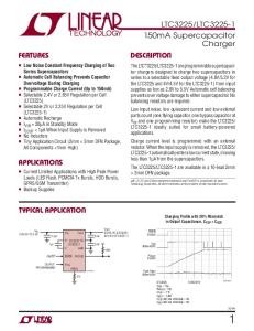
Figure 1 Efficiency vs. Line Voltage
Brightness Power Semiconductor BP2808_DS_EN_V2.0
Dec 2009
265
85
105 125 145 165 185 205 225 245 265
Figure 2 Output Current vs. Line Voltage
Page 1
Typical Application Circuit
Figure 3 Typical Application Circuit for AC supply
Figure 4 Typical Application Circuit for DC Supply
Brightness Power Semiconductor BP2808_DS_EN_V2.0
Dec 2009
Page 2
Pin ASSIGNMENT
Figure 5 Pin Assignment
Pin Description PIN No.
PIN NAMES
1
GND
2
LN
3
VDD
Input Supply Pin. Must be locally bypassed.
4
OUT
Drain of internal power switch, source of external power switch.
5
NC
No connection
6
CS
Current sense input, sampling resistor connected between CS and GND
7
RT
Fixed turn off time setting
8
DIM
DESCRIPTION Signal and power ground. Connect directly to ground plane. Line voltage compensation of the peak threshold. Sensing the voltage between LN and VDD.
Enable switch, analog and PWM dimming input.
ORDERING INFORMATION ORDERING PART
PACKAGE
BP2808ESO8
Brightness Power Semiconductor BP2808_DS_EN_V2.0
Dec 2009
SOP8
TEMPERATURE
TRANSPORT
RANGE
MEDIA
-40 oC to 85 oC
Tape and Reel
MARKING
BP2808
Page 3
ABSOLUTE MAXIMUM RATINGS (Note 1) SYMBOL
ITEMS
VALUE
UNIT
VDD
Supply Voltage
-0.3~18
V
LN
Line voltage compensation
-0.3~18
V
Drain of internal power switch.
-0.3~20
V
Pin of current sense
-0.3~6
V
Enable switch, analog and PWM dimming
-0.3~6
V
-0.3~6
V
OUT CS DIM
input. RT
Fixed turn off time setting
IOUT
Output current of power switch
0.8
A
Power Dissipation (Note 2)
0.5
W
PTR
Thermal Resistance SOP8(θJA)
150
TJ
Operation Junction Temperature Range
-40 to 150
o
Storage Temperature
-55 to 150
o
PDMAX
TSTG
ESD Susceptibility (Note 3)
o
C /W C C
3
kV
Note 1: Absolute Maximum Ratings indicate that operating beyond these ratings may damage the device. Recommended Operating Range indicates that the device is functional in that range, but do not guarantee specific performance limits. Electrical Characteristics state DC and AC electrical specifications under particular test conditions which guarantee specific performance limits. This assumes that the device is within the Operating Range. Specifications are not guaranteed for parameters where no limit is given, however, the typical value is a good indication of device performance. Note 2: The maximum power dissipation must be decreasing with elevating temperatures and is dictated by TJMAX, θJA, and the ambient temperature TA. The maximum allowable power dissipation is PDMAX = (TJMAX - TA)/ θJA or the lower number given in Absolute Maximum Ratings. Note 3: Human body model, 100pF capacitor discharged through a 1.5kΩ resistor.
RECOMMENDED OPERATING RANGE SYMBOL VDD TOPT
Brightness Power Semiconductor BP2808_DS_EN_V2.0
Dec 2009
ITEMS VDD Supply Voltage Operating Temperature
VALUE 0 ~ 16 -40 to +85
UNIT V o
C
Page 4
ELECTRICAL CHARACTERISTICS (Note 4, 5) (The following specifications apply for VIN=12V, TA=25 oC, unless specified otherwise.) SYMBOL