LT4351 MOSFET Diode-OR Controller DESCRIPTION
FEATURES Low Loss Replacement for ORing Diode in Multiple Sourced Power Supplies n External N-Channel MOSFETs for High Current Capability n Internal Boost Regulator Supply for MOSFET Gate Drive n Wide Input Range: 1.2V to 18V n Fast Switching MOSFET Gate Control n Input Under and Overvoltage Detection n STATUS and FAULT Outputs for Monitoring n Internal MOSFET Gate Clamp n Available in a 10-pin MSOP Package
The LT®4351 creates a near ideal diode using external single or back-to-back N-channel MOSFETs. This ideal diode function permits low loss ORing of multiple power sources. Power sources can easily be ORed together to increase total system power and reliability with minimal effect on supply voltage or efficiency. Disparate power supplies can be efficiently ORed together.
n
The IC monitors the input supply with respect to the load and turns on the MOSFET(s) when the input supply is higher. If the MOSFET’s RDS(ON) is sufficiently small, the LT4351 will regulate the voltage across the MOSFET(s) to 15mV. A STATUS pin indicates the MOSFET on-state.
APPLICATIONS n n n n
An internal boost regulator generates the MOSFET gate drive voltage. Low operating voltage allows for ORing of supplies as low as 1.2V.
Paralleled Power Supplies Uninterrupted Supplies High Availability Systems N + 1 Redundant Power Supplies
The LT4351 will disable power passage during undervoltage or overvoltage conditions. These voltages are set by resistive dividers on the UV and OV pins. The undervoltage threshold has user programmable hysteresis. Overvoltage detection is filtered to reduce false triggering.
L, LT, LTC, LTM, Linear Technology, the Linear logo and Burst Mode are registered trademarks and PowerPath and ThinSOT are trademarks of Linear Technology Corporation. All other trademarks are the property of their respective owners.
The LT4351 is available in a 10-pin MSOP package.
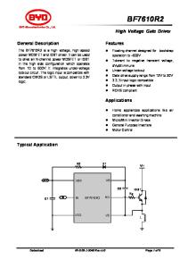
TYPICAL APPLICATION Dual 5V Redundant Supply Si4862DY POWER SUPPLY 1
Si4862DY 5V COMMON
5V 4.7µH
10µF
1×
VIN MBR0530
232Ω 1% 1.47k 1%
GATE
OUT
1×
LOAD
1µF OUT
GATE
VDD
MBR0530 24.9k 1%
CLOAD
1µF
5V
SW UV OV
VIN VDD
LT4351
STATUS FAULT
GND
STATUS
LT4351
GND
MBR0530 MBR0530
SW UV
FAULT
10µF 4.7µH
POWER SUPPLY 2
OV 4351 TA01
24.9k 1% 232Ω 1% 1.47k 1%
4351fd
1
LT4351 ABSOLUTE MAXIMUM RATINGS
PIN CONFIGURATION
(Note 1)
VIN Voltage................................................. –0.3V to 19V OUT Voltage.............................................. –0.3V to 19V VDD Voltage............................................... –0.3V to 30V FAULT, STATUS Voltages........................... –0.3V to 30V FAULT, STATUS Current........................................... 8mA UV, OV Voltages.......................................... –0.3V to 9V SW Voltage............................................... –0.3V to 32V Operating Temperature Range LT4351C ................................................... 0°C to 70°C LT4351I ................................................ –40°C to 85°C Junction Temperature (Note 2)............................. 125°C Storage Temperature Range................... –65°C to 150°C Lead Temperature (Soldering, 10 sec)................... 300°C
TOP VIEW GATE VDD VIN SW GND
1 2 3 4 5
10 9 8 7 6
OUT STATUS FAULT UV OV
MS PACKAGE 10-LEAD PLASTIC MSOP TJMAX = 125°C, θJA = 120°C/W
ORDER INFORMATION LEAD FREE FINISH
TAPE AND REEL
PART MARKING
PACKAGE DESCRIPTION
TEMPERATURE RANGE
LT4351CMS#PBF
LT4351CMS#TRPBF
LTZZ
10-Lead Plastic MSOP
0°C to 70°C
LT4351IMS#PBF
LT4351IMS#TRPBF
LTA1
10-Lead Plastic MSOP
–40°C to 85°C
Consult LTC Marketing for parts specified with wider operating temperature ranges. Consult LTC Marketing for information on non-standard lead based finish parts. For more information on lead free part marking, go to: http://www.linear.com/leadfree/ For more information on tape and reel specifications, go to: http://www.linear.com/tapeandreel/
ELECTRICAL CHARACTERISTICS The l denotes the specifications which apply over the full operating
temperature range, otherwise specifications are at TA = 25°C. VIN = VOUT = 5V, VDD = 16.1V, VUV = 0.4V, VOV = 0.2V, GATE Open, unless otherwise specified. SYMBOL
PARAMETER
CONDITIONS
MIN
TYP
MAX
UNITS
Supply and Protection VIN
Operating Range
IVIN
VIN Supply Current
VIN = 1.2V, VOUT = 1.1V, VDD = 12.3V VIN = 18V, VOUT = 17.9V, VDD = 29.1V
l l
VUV(TH)
Undervoltage Turn-Off Voltage Threshold
UV Falling
l
IUV(HYST)
IUV Hysteresis
Difference Between IUV at VUV(TH) + 10mV and VUV(TH) – 10mV
l
IUV
UV Input Bias Current
VUV = VUV(TH) + 10mV
l
VOV(TH)
Overvoltage Threshold
OV Rising
l
l
1.2
18
V
1.41 1.71
2 2.1
mA mA
290
300
310
mV
7
10
13
µA
–100
–400
nA
300
310
mV
290
4351fd
2
LT4351 ELECTRICAL CHARACTERISTICS The l denotes the specifications which apply over the full operating
temperature range, otherwise specifications are at TA = 25°C. VIN = VOUT = 5V, VDD = 16.1V, VUV = 0.4V, VOV = 0.2V, GATE Open, unless otherwise specified.
SYMBOL
PARAMETER
CONDITIONS
TYP
MAX
UNITS
IOV
OV Input Bias Current
VOV = VOV(TH) – 10mV
l
MIN
–100
–400
V
VF(ON)
FAULT Pin On-Voltage
IF = 5mA in Fault Condition
l
0.14
0.25
V
IF(OFF)
FAULT Pin Leakage Current
VF = 30V, VIN = 4.9V
l
0.04
1
µA
VBR
Boost Regulation Trip Voltage
Measured as VDD to VIN, Rising Edge
l
10.7
11.4
tOFF
Boost Supply Off-Time
ISWLIM
Boost Supply Switch Current Limit
l
350
450
650
mA
VIOR
Input-to-Output Regulated Voltage
l
4
15
25
mV
∆VGL
Gate Voltage Limit
VIN = 5V, VOUT = 4.9V, VDD = 13V Measured with Respect to VDD
l
–2.3
–3
V
∆VG(MAX)
Maximum Gate Voltage
VIN = 5V, VOUT = 4.9V, VDD = 16.1V Measured with Respect to VOUT
l
7.4
7.8
V
VG(OFF)
Gate Off-Voltage
VOUT = 5.1V
l
0.16
0.30
V
IGSO
Gate Source Current
VOUT = 4.9V, VGATE = 9V
IGSK
Gate Sink Current
VOUT = 5.1V, VGATE = 9V
VDD
Operating Range
IVDD
VDD Supply Current
Boost Supply 10.2
600
V ns
Gate Drive
7
0.670
A
0.670 l
VIN = 1.2V, VOUT = 1.1V, VDD = 12.3V, GATE Open VIN = 18V, VOUT = 17.9V, VDD = 29.1V, GATE Open
A 30
V mA mA
l l
3 3.6
4 5.6
l
0.75
1
210
230
mV
Status Functions ∆VGIS
Minimum Gate Voltage for Turning VOUT = 4.9V, ISTATUS = 1mA On Status
VIOGF
VIN to VOUT Fault Voltage with Open Gate
VOUT Falling, Measured with Respect to VIN
VST(ON)
Status Pin On-Voltage
IST = 5mA, VOUT = 4.9V, Status On
l
0.13
0.25
V
IST(OFF)
Status Pin Leakage Current
VST = 30V, Status Off, VIN = 4.9V
l
0.04
1
µA
Note 1: Stresses beyond those listed under Absolute Maximum Ratings may cause permanent damage to the device. Exposure to any Absolute Maximum Rating condition for extended periods may affect device reliability and lifetime.
185
V
Note 2: TJ is calculated from the ambient temperature TA and power dissipation PD according to the following formula: TJ = TA + (PD • 120°C/W)
4351fd
3
LT4351 TYPICAL PERFORMANCE CHARACTERISTICS Undervoltage Threshold vs Temperature
Overvoltage Threshold vs Temperature 305
VIN = 1.2V VIN = 5V VIN = 12V VIN = 20V
308 306
VOV(TH) (mV)
VUV(TH) (mV)
VIN = 1.2V VIN = 5V VIN = 12V VIN = 20V
303
304 302 300 298 296 294
308 306 304
301 299 297
50 25 0 75 TEMPERATURE (°C)
–25
100
293 –50
125
–25
50 25 0 75 TEMPERATURE (°C)
100
290
125
25
310 308
20
VIN = 5V
298 296
8
10 12 14 16 18 20 VIN (V)
16
15
10
5
294
VIN = 5V
18
TURN-OFF DELAY (µs)
OV HYSTERESIS (mV)
300
6
Overvoltage Turn-Off Delay vs Overvoltage Overdrive
20
306
302
4
4351 G03
Overvoltage Hysteresis vs Temperature
304
2
0
4351 G02
Overvoltage Threshold vs VIN
14 12 10 8 6 4 2
292 0
2
4
6
8
0 –50
10 12 14 16 18 20 VIN (V)
–25
50 0 75 25 TEMPERATURE (°C)
IVIN vs Temperature
1.9 1.8
100
0
125
35 20 15 10 25 30 5 OV VOLTAGE ABOVE THRESHOLD (mV)
4.5
VIN = 1.2V VIN = 5V VIN = 12V VIN = 20V
3451 G06
IVDD vs Temperature
Gate Off-Voltage vs Temperature 0.50
VIN = 1.2V VIN = 5V VIN = 12V VIN = 20V
4.0
0.45 VIN = 5V VOUT = 5V
0.40
1.7
0.35
1.5 1.4
3.5
VGOFF (V)
IVDD (mA)
1.6
3.0
1.3
0.30 0.25 VIN = 5V VOUT = 5.1V
0.20 0.15
1.2
0.10
2.5
1.1 1.0 –50
0
4351 G05
4351 G04
IVIN (mA)
298
294
4351 G01
2.0
300
292
290 –50
290
302
296
295
292
VUV(TH) (mV)
Undervoltage Threshold vs VIN 310
VUV(TH) (mV)
310
TA = 25°C, unless otherwise noted.
0.05 –25
50 25 0 75 TEMPERATURE (°C)
100
125
4351 G07
2.0 –50
–25
50 25 0 75 TEMPERATURE (°C)
100
125
4351 G08
0 –50
–25
50 25 0 75 TEMPERATURE (°C)
100
125
4351 G09
4351fd
4
LT4351 TYPICAL PERFORMANCE CHARACTERISTICS GATE Pin Turn On and Off Waveform with 10nF Capacitor Load
TA = 25°C, unless otherwise noted.
Typical SW Pin Waveform
TURN ON
VSW 5V/DIV
VGATE 2V/DIV
TURN OFF
50ns/DIV VIN = 5V VOUT = 4.9V TO 5.1V SQUARE WAVE
4351 G10
VIN = 5V L = 4.7µH
500ns/DIV
4351 G11
SW Pin Waveform at Maximum Boost Regulator Output
Typical SW Pin Waveform
VSW 5V/DIV
VSW 5V/DIV
VIN = 5V 4.7µH INDUCTOR
10µs/DIV
4351 G12
VIN = 5V 4.7µH INDUCTOR
10µs/DIV
4351 G13
4351fd
5
LT4351 PIN FUNCTIONS GATE (Pin 1): MOSFET Gate Drive Pin. This pin is tied to the gate(s) of the external N-channel MOSFET(s). The GATE pin drives high when UV is above the VUV(TH) threshold, OV is below the VOV(TH) threshold and VIN is greater than OUT by 15mV. When not driven high, GATE actively pulls to GND. GATE can sink or source up to 600mA. VDD (Pin 2): Gate Drive Supply Pin. This is the supply pin for the gate drive amplifier. It is either generated by the onboard boost regulator or supplied externally. When turning on the MOSFET(s), a large high current pulse flows through this pin. Bypass the pin with a 1µF capacitor placed in close proximity to the part. The voltage on this pin is also the feedback for the boost regulator. If the VDD voltage exceeds the VIN voltage by 10.7V, the boost switch is held off. VIN (Pin 3): Input Supply Pin. This pin is the supply pin for the control circuitry and the boost regulator. It is also one input in conjunction with OUT for controlling the MOSFET(s). Bypassing should include a low ESR/ESL capacitor placed in close proximity to the part. SW (Pin 4): Boost Regulator Switch Pin. This pin is the boost regulator switch output. It is connected to the boost inductor and the boost diode. Peak switch current is limited internally to 450mA. A Schottky diode between GND and SW is required. If an external VDD supply is used, leave this pin open. GND (Pin 5): Device Ground Pin. This pin is ground for the boost switch, gate driver as well as the control circuitry. Tie the VIN and VDD bypass capacitors and ground plane close to this pin to minimize the effects of switching currents on part performance. OV (Pin 6): Overvoltage Shutdown Pin. This pin is used for input overvoltage detection. It is connected to a resistive divider from VIN. When the voltage exceeds the OV threshold (0.3V), GATE is pulled to GND disabling power transfer. In addition, the FAULT pin pulls low indicating a
fault. Overvoltage detection has filtering on it to prevent false triggering. The filtering depends on the level of overdrive. Filtered tripping will occur when OV exceeds 0.3V. If OV exceeds 0.33V, the gate immediately turns off (no filtering). If overvoltage detection is not required, ground the OV pin. See the Applications Information section for further information. UV (Pin 7): Undervoltage Shutdown Pin. This pin is used for the undervoltage detect function. It is connected to a resistive divider from VIN. When the voltage is below the UV threshold, GATE pulls to GND disabling power transfer. In addition, the FAULT pin pulls low indicating a fault. When the UV pin voltage drops below the threshold, a 10µA current is pulled from the divider to provide hysteresis. If undervoltage detection is not required, tie the UV pin to a voltage greater than 320mV and not greater than VIN. Do not force more than 9V on UV due to an internal clamp. See the Applications Information section for further information. FAULT (Pin 8): Fault Comparator Status Pin. This pin pulls low when a fault occurs. A fault has occurred if the UV pin is below threshold or the OV pin is above threshold. The FAULT pin low indicates that there is a problem with the VIN (source) supply. GATE is pulled to GND during a fault, disabling the MOSFET(s) and prohibits common supply contamination. If the GATE pin goes to compliance (GATE equals the lesser of VDD – 2.3V or OUT + 7.4V) and VIN is greater than OUT by more than 0.21V, FAULT turns on as an indicator that the MOSFETs are probably not functioning. Leave this pin open if not used. STATUS (Pin 9): MOSFET Status Pin. This pin pulls low when GATE is above VIN by more than 0.7V and VIN is greater than OUT by 15mV. This indicates the MOSFET is on. Leave this pin open if not used. OUT (Pin 10): Common Supply Pin. This pin is connected to the supply common and is used in conjunction with VIN as one input controlling the MOSFET(s).
4351fd
6
LT4351 BLOCK DIAGRAM TO COMMON SUPPLY FROM INDIVIDUAL SUPPLY VIN
VOUT
4
2
3
GATE
10.7V
REG
–
ENABLE
+
600ns ONE SHOT
QSW
1 VIN
VDD
SW
ENABLE
+ DRIVER
–
+
15mV
+ – OUT
–
R2 7
UV
RB R1
0.3V 6
+
+
– –
OV
RA
– 0.3V
OPEN OUT MOSFET DETECT
VIN
CUV
COV 0.33V
STATUS
10
9
ST
COVF
– FAULT
+
8
+ 5
GND 4351 BD
4351fd
7
LT4351 OPERATION Increasingly, system designers have to deal with multiple supply sources. The multiplicity may provide parallel, redundant supplies for increased reliability or provide a means of connecting disparate supplies. In all cases the desire is for behavior like a diode but with no loss or voltage drop. ORing diodes have been the conventional means of connecting these supplies. The disadvantage of this approach is that diodes introduce efficiency loss because of their forward voltage drop. This variable voltage drop also degenerates supply tolerance. Additionally, diodes provide no information concerning the status of the sourcing supply. Separate control must also be added to ensure that a supply that is out of range is not allowed to affect the common supply. The LT4351 eliminates these problems by using N-channel MOSFETs as the pass elements. The MOSFET is turned on when power is being passed, allowing for a low voltage drop from the supply to the load. When the input source voltage drops below the output common supply voltage it turns off the MOSFET, thereby matching the function and performance of an ideal diode. The LT4351 drives either a single MOSFET or dual backto-back MOSFETs. Dual MOSFETs are chosen to eliminate current flow from the input supply to the output supply when the VIN voltage is greater than OUT. A driver amplifier monitors the input (VIN) and output (OUT) and controls the MOSFETs. If VIN exceeds OUT by 15mV, GATE goes high and turns on the MOSFET(s) allowing for power passage. Undervoltage and overvoltage comparators CUV , COV and COVF also control power passage. A resistive divider in conjunction with the UV and OV pins sets appropriate thresholds such that the MOSFET(s) is off when the UV pin is below 300mV or OV pin is above 300mV. To help deal with the transients on the supply lines, the UV input has current hysteresis. When the UV voltage drops below the 300mV threshold, a 10µA current is pulled from the pin. Thus the user can set the hysteresis level through appropriate values in the divider. Overvoltage shutdown occurs in two stages. The first occurs when the OV pin exceeds the 300mV reference. When
OV just exceeds the reference, an internal capacitor starts charging, delaying the signal to turn off the MOSFET(s). The second occurs when the OV pin exceeds 330mV. The OVF comparator will immediately trip pulling GATE to GND. This affords a delay inversely proportional to the amount of overdrive. This also provides for glitch immunity without compromising response time in the event of a serious overvoltage condition. The FAULT output indicates the status of the COV , COVF and CUV comparators. It pulls low during a fault condition. It also pulls low when GATE is at compliance and VIN > OUT by more than 0.21V indicating a probable nonfunctioning MOSFET. Compliance occurs when GATE is at the lesser of OUT + 7.4V or VDD – 2.3V. FAULT derives its drive from the greater of VIN or OUT. It is active if VIN or OUT is greater than 0.9V. If VIN or OUT is below this level, the output state is not guaranteed. The gate drive consists of a high current, wide bandwidth amplifier (driver). When the amplifier is enabled, it attempts to regulate the GATE voltage such that the voltage across the MOSFET(s) is approximately 15mV. If the MOSFET(s) on resistance is so high as to prevent regulation, then GATE goes to compliance and the MOSFET(s) fully turns on. The inputs to the amplifier are VIN and OUT. The GATE pin sources current from VDD and sinks current to GND. The maximum GATE to VIN voltage is the lesser of VDD – 2.3V or 7.4V above VOUT or VIN (internal clamp voltage). The STATUS comparator, ST, pulls low when GATE exceeds VIN by 0.7V. This occurs when VIN > OUT + 15mV. The STATUS pin pulls low as an indication that power is passing through the MOSFET(s). If VIN is greater than OUT by 0.21V and GATE > VIN + 7.4V or at compliance (GATE = VDD – 2.3V), STATUS will go high as an indication of a likely open MOSFET. FAULT will pull low in this state indicating the probable fault. The gate drive amplifier and STATUS function derive power from VDD. The circuit requires VDD > 2.5V. If VDD is present, the gate drive amplifier and STATUS are active independent of the state of VIN. If in a fault, GATE pulls actively low. In the event of VDD collapse there still is an active pull-down (though of lesser strength) of GATE powered from OUT, guaranteeing turn off. 4351fd
8
LT4351 OPERATION The on-chip boost regulator uses a constant off-time control scheme. When VDD is below the regulation trip voltage, the switch turns on after a 600ns off-time. When the switch turns on current ramps up in the inductor until the current limit is reached (450mA). The switch turns off and the inductor’s current flows through the external diode to charge up the VDD capacitor. If VDD is still too low, the switch turns on again after a fixed off-time of 600ns.
The boost regulator regulates VDD to approximately 10.7V above VIN When VDD is above this level, the SW transistor turn-on is disabled. When VDD falls below this level by the hysteresis level, the SW transistor is allowed to turn on. There is approximately 0.15V of hysteresis.
APPLICATIONS INFORMATION Setting Fault Thresholds The gate drive amplifier implements the ideal diode function. The fault comparators (UV and OV) prevent out of range input voltages from affecting the output by disabling the amplifier during these conditions. Think of the UV and OV as gating the ideal diode function, something a regular diode cannot do. A resistive divider from VIN to UV and one from VIN to OV are the usual way of setting the FAULT thresholds. For UV the resistor values are set by:
R2 =
UVHYST IUVHYST
R1=
VUV • R2 UVFAULT – VUV
VIN
R1
UV
VUV 300mV
R1
IHYS 10µA
RA =
0.3V R A ,RB Divider Current
It is possible to do both dividers together using only three resistors though with more interdependence in components (Figure 3). The input bias current for UV and OV is less than 200nA, so keep resistor values less than 10k. VIN R3
R2
UV
OV RB = FAULT – 1 R A VOV
VIN
VIN R2
The divider on the OV pin is a straightforward resistive divider (Figure 2):
where OVFAULT is the desired overvoltage trip point at the input and VOV is the OV pin threshold (0.3V). The OV pin has 7mV of voltage hysteresis at room.
where UVHYST is the desired undervoltage hysteresis at the input. UVFAULT is the desired undervoltage trip voltVIN
age at the input. VUV is the part undervoltage trip point (0.3V) and IHYSTUV is the undervoltage hysteresis current (10µA). See Figure 1.
VUV 300mV
IHYS 10µA
RB OV
R2B UV
VOV 300mV
R2
R2A OV
RA R1
C1
UV R1
4351 F02 4351 F01
UV TURNING ON
4351 F03
UV TURNING OFF
Figure 1
Figure 2
Figure 3
4351 F04
Figure 4 4351fd
9
LT4351 APPLICATIONS INFORMATION In that case, the resistor values are set by: UV R3 = HYST IUVHYST R2 =
R1=
Boost Regulator The boost regulator will start working as soon as VIN is greater than 0.85V. The regulator will supply all the current for the gate drive amplifier. While the amplifier itself requires only about 3mA, larger current pulses are required when charging the MOSFET gate. The reservoir capacitor on VDD will provide this current (Figure 6).
UVFAULT •V OVFAULT OV • R3 UVFAULT – VUV
VUV –
VOV • UVFAULT • R3 OVFAULT • (UVFAULT – VUV )
VIN
Hysteresis helps prevent erratic behavior due to the noise on VIN. Two of the most common noise sources are: VIN dipping when the MOSFETs first turn on and draw down the voltage on the VIN capacitors, and the boost regulator switch turning on and drawing current from the VIN capacitors. Use low ESR capacitors for VIN and OUT filtering. Note that because the UV pin uses current hysteresis, placing a capacitor on UV to ground to filter noise will reduce the effective hysteresis. Filtering can be achieved by splitting the R2 resistor, as shown in Figure 4. To defeat undervoltage fault detection, the UV pin should be tied higher than 0.33V. UV can be tied to VIN provided VIN < 9V. Overvoltage fault detection can be defeated by grounding the OV pin. Do not exceed VIN. INPUT REFERRED
OV REFERRED OVERVOLTAGE FAULT: GATE LOW
OVFAULT
UVFAULT + UVHYST UVFAULT
VUV = 0.33V
OVERVOLTAGE FILTERED FAULT GATE CONTROLLED BY VIN – VOUT UNDERVOLTAGE HYSTERESIS UNDERVOLTAGE FAULT: GATE LOW
UV REFERRED
VUV = 0.3V VOV > 0.3V
VUV < 0.3V
VOV = 0.3V 4351 F05
Figure 5. Graphical Representation of the UV and OV Functions
External Shutdown To externally turn off the MOSFETs, such as to disable the supply, use an open-collector transistor pulling down on the UV pin. Note this will not turn off the boost regulator which will continue to operate.
LT4351 SW
L1 D1 VDD
QSW D2
CDD
GND
4351 F06
Figure 6
The regulator performance is relatively insensitive to the inductor value. The inductor value does control the frequency of operation. A 4.7µH inductor is recommended for VIN voltages less than 10V and 10µH for VIN voltages greater than 10V. Several inductors that work well with the LT4351 are listed in Table 1. Many different sizes and shapes are available. Consult each manufacturer for more detailed information and for their entire selection of related parts. The switching frequency for the boost regulator is around 1MHz so ferrite core inductors should be used to obtain the best efficiency. The inductor must handle a peak current of 0.7A minimum and have a DC resistance of 0.5Ω or less. Shielded inductors are recommended to reduce the noise due to inductive switching. Table 1. Recommended Inductors PART NUMBER
IND (µH)
DCR (mΩ)
VENDOR
LPS3314-472ML LPS4012-103ML
4.7 10
175 350
Coilcraft 847-639-6400 www.coilcraft.com
744029004 744042100
4.7 10
200 150
Würth Elektronik www.we-online.com
SD3112-4R7-R SD3118-100-R
4.7 10
246 295
Coiltronics www.coiltronics.com
4351fd
10
LT4351 APPLICATIONS INFORMATION For VIN less than 2V, choose a DC resistance less than 0.2Ω.
VDD Capacitor Selection
Note that VDD current referred to the input supply is higher. A first order approximation of the input current is:
Low ESR (Equivalent Series Resistance) capacitors should be used on VDD to minimize the output ripple voltage. Multilayer ceramic capacitors are the best choice, as they have a very low ESR and are available in very small packages. Always use a capacitor with a voltage rating at least 12V greater than VIN.
10.6 I VDD I VINVDD = 1+ • VIN 80% Under normal operation, the VDD current is under 10mA and the boost regulator operates in Burst Mode® operation. If any additional load is added, ensure that the regulator is capable of supplying that load. As the load is increased, the boost regulator will switch into continuous mode operation. Further increases in load will collapse the boost regulator voltage. Operating the regulator with increased load will cause increased IC power dissipation and temperature, which must be taken into consideration. A 100ns delay from detecting the switch current limit to turning off the power switch produces an overshoot of the inductor current from the 0.45A switch limit. The amount of overshoot depends on the boost regulator inductance. Choosing an inductor that can handle 0.75A peak current will be sufficient for the recommended inductors. Diode Selection Schottky diodes, with their low forward voltage drop and fast switching speed, are the best match for the LT4351 boost regulator. Select a diode that can handle 0.75A peak current and a reverse breakdown of 15V greater than the maximum VIN.
Capacitors Two types of input capacitors are generally needed for the LT4351. The first is a large bulk capacitor that takes care of ringing associated with inductance of the input supply lines and provides charge for the load when switching the MOSFET. The input parasitic inductance in conjunction with CB and its ESR create an LCR network. The input LCR can be stimulated by the boost regulator switch current or load current transients when the MOSFETs are on. To reduce ringing associated with input inductance, CB should be: 4 • LIN CB ≥ 2 RESR where CB is the capacitor value, RESR is the capacitor’s ESR and LIN is the inductance of the input lines. While damped ringing is not necessarily bad, it may produce unexpected results as the LT4351 ideal diode reacts to the varying VIN to OUT voltage. Typically an electrolytic or tantalum low ESR capacitor would be used. Figure 7a illustrates VIN for a low value of CB and Figure 7b shows it with a correctly sized value.
VIN 200mV
VIN 200mV
10µs/DIV
4351 F07a
Figure 7a. Example of Input Voltage Ringing with Low CIN Capacitor at MOSFET Turn Off
10µs/DIV
4351 F07b
Figure 7b. Example of Input Voltage with Sufficient CIN Capacitor at MOSFET Turn Off 4351fd
11
LT4351 APPLICATIONS INFORMATION MOSFET Selection
As an example, for 500nH of inductance and RESR of about 100mΩ, then:
C≥
The LT4351 uses either a single N-channel MOSFET or back-to-back N-channel MOSFETs as the pass element. Back-to-back MOSFETs prevent the MOSFET body diode from passing current.
4 • 500nF = 200µF 0.12
Check vendor data for ESR and iterate to get the best value. Additional CB capacitance may be required for load concerns.
Use a single MOSFET if current flow is allowable from input to output when the input supply is above the output (limited overvoltage protection). In this case the MOSFET should have a source on the input side so the body diode conducts current to the load. Back-to-back MOSFETs are normally connected with their sources tied together to provide added protection against exceeding maximum gate to source voltage.
If the boost regulator is being used, place a 10µF low ESR ceramic capacitor from VIN to GND. Place a 10µF and a 0.1µF ceramic capacitor close to VIN and GND. These capacitors should have low ESR (less than 10mΩ for the 10µF and 40mΩ for the 0.1µF). These capacitors help to eliminate problems associated with noise produced by the boost regulator. They are decoupled from the VIN supply by a small 1Ω resistor, as shown in Figure 8. The LT4351 will perform better with a small ceramic capacitor (10µF) on OUT to GND.
Selection of MOSFETs should be based on RDS(ON), BVDSS and BVGSS. BVDSS should be high enough to prevent breakdown when VIN or OUT are at their maximum value. RDS(ON) should be selected to keep within the MOSFET power rating at the maximum load current (I2 • RDS(ON)) BVGSS should be at least 8V. The LT4351 will clamp the GATE to 7.5V above the lesser of VIN or OUT. For backto-back MOSFETs where sources are tied together, this allows the use of MOSFETs with a VGS max rating of 8V or more. If a single MOSFET is used, care must be taken to ensure the VGS max rating is not exceeded. When the MOSFET is turned off, the GATE voltage is near ground, the source at VIN. Thus, MOSFET VGS max must be greater than VIN(MAX).
External Boost Supply The VDD pin may be powered by an external supply. In this case, simply omit the boost regulator inductor and diode and leave the SW pin open. Suitable VDD capacitance (minimum of a 1µF ceramic) should remain due to the current pulses required for the gate driver. The VDD current consists of 3.5mA of DC current with the current required to charge the MOSFET’s gate which is dependent on the gate charge required and frequency of switching. Typically the average current will be under 10mA.
If a single MOSFET is used with source to VIN, then BVGSS should be greater than the maximum VIN since the MOSFET gate is at 0.2V when off.
LIN PARASITIC VIN CV3 10µF CB
1Ω CV1 10µF
GATE VIN CV2 0.1µF
LT4351 GND 4351 F08
Figure 8. VIN Capacitors
4351fd
12
LT4351 APPLICATIONS INFORMATION The gate drive amplifier will attempt to regulate the voltage across the MOSFETs to 15mV. Regulation will be achieved if: 15mV RDS < for two MOSFETs and 2 • ILOAD
RDS