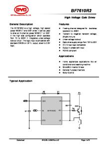
Elastomer O-Ring Seals A B C D E F G H I
– Face/Primary Ring – Seat/Mating Ring – Spring – O-Ring – Retainer – Disc F – Anti-X-Ring G – Snap Ring – Set Screws
I D
C E A H B
D
Product Description Rugged Type 8-1/8-1T mechanical seals are available in a wide variety of elastomers for handling practically every industrial fluid. All components are held together by a snap ring in a unitized construction design. ■
■
■
■
General industrial applications including chemical processing, food and beverage, petrochemical processing, pharmaceutical, pipeline, power generation and pulp and paper.
■ ■ ■
Temperature: -40°C to 260°C/-40°F to 500°F (depending on materials used)
■
■
Compact design permits use in all types of rotating equipment centrifugal pumps, mixers and agitators.
Pressure: Type 8-1 Type 8-1T
22.5 bar g/325 psig 13.8 bar g/200 psig
Speed: Up to 25 m/s / 5000 fpm NOTE: For applications with speeds greater than 25 m/s/ 5000 fpm, a rotating seat (RS) arrangement is recommended.
Seals can be repaired easily on-site or at any John Crane Service Center. Seals can be shaft mounted or built into a cartridge as illustrated above.
Design Features ■
Performance Capabilities ■
Typical Applications
O-Ring Design.
■
Positive Mechanical Drive Design Eliminates Slippage.
■
Multiple Springs Provide Precise Face Loading.
■
Full (8-1) and Narrow (8-1T) Cross-section Designs.
■
Chemicals
■
Crystallizing fluids
Caustics
■
Lubricating liquid
Acids
■
Hydrocarbons
Aqueous solutions
■
Solvents
8-1/8-1T
TYPE 8-1/8-1T
8-1/8-1T
TYPE 8-1/8-1T Elastomer O-Ring Seals Type 8-1 Typical Arrangement/Dimensional Data D11 Pin
L45 Pin Ext.
(N) number of pins (D12) pin diameter Pin press fit into collar or impeller. Engages holes in retainer. Design option standard on Type 8-1 Seals only.
0.040" MIN. 16-32µ"
L9 D4 MIN. BORE
L3 ± 0.031" W. H.
D3 SEAL OD
D ± 0.002"
20˚ For ease of installation, the lead-in edge of shaft or sleeve should be chamfered as shown.
Type 8-1 Dimensional Data (inches) Seal Size/D (inches) 0.500 0.625 0.750 0.875 1.000 1.125 1.250 1.375 1.500 1.625 1.750 1.875 2.000 2.125 2.250 2.375 2.500 2.625 2.750 2.875 3.000 3.125 3.250 3.375 3.500 3.625 3.750 3.875 4.000 4.125 4.250 4.375 4.500 4.625 4.750 4.875 5.000 5.125 5.250 5.375 5.500 5.625 5.750 5.875 6.000
D3 1.031 1.187 1.312 1.437 1.562 1.687 1.875 2.000 2.125 2.375 2.500 2.625 2.750 3.000 3.125 3.250 3.375 3.500 3.625 3.750 3.812 3.937 4.125 4.250 4.375 4.500 4.625 4.750 4.875 5.000 5.250 5.375 5.500 5.625 5.750 5.875 6.000 6.125 6.500 6.625 6.750 6.875 7.000 7.125 7.250
D4 1.156 1.312 1.437 1.562 1.750 1.875 2.000 2.125 2.250 2.500 2.625 2.750 2.875 3.125 3.250 3.375 3.500 3.625 3.750 3.875 4.000 4.062 4.250 4.375 4.500 4.625 4.750 4.875 5.000 5.250 5.375 5.500 5.625 5.750 5.875 6.000 6.125 6.260 6.625 6.750 6.875 7.000 7.125 7.250 7.375
D11 .— .— .— 1.140 .— 1.437 1.562 1.687 1.812 2.000 2.125 2.250 2.375 2.593 2.718 2.843 2.968 3.062 3.187 3.312 3.406 3.531 3.687 3.812 3.937 4.062 4.187 4.312 4.437 4.656 4.781 4.906 4.968 .— 5.250 5.375 5.500 5.625 5.750 5.875 6.000 6.125 6.250 6.375 6.500
D12 .— .— .— 0.156 .— 0.187 0.187 0.187 0.187 0.187 0.187 0.187 0.187 0.250 0.250 0.250 0.250 0.312 0.312 0.312 0.312 0.312 0.312 0.312 0.312 0.312 0.312 0.312 0.312 0.312 0.312 0.312 0.312 .— 0.312 0.312 0.312 0.312 0.312 0.312 0.312 0.312 0.312 0.281 0.281
Working Height L3 0.812 0.750 0.875 0.937 1.000 1.062 1.062 1.125 1.125 1.375 1.375 1.375 1.375 1.687 1.687 1.687 1.687 1.687 1.687 1.687 1.687 1.687 1.687 1.687 1.687 1.687 1.687 1.687 1.687 1.687 1.687 1.687 1.687 1.687 1.687 1.687 1.687 1.687 2.000 2.000 2.000 2.000 2.000 2.000 2.000
L9 0.156 0.156 0.187 0.187 0.187 0.218 0.187 0.187 0.187 0.281 0.281 0.281 0.281 0.343 0.343 0.343 0.343 0.343 0.343 0.343 0.343 0.343 0.343 0.343 0.343 0.343 0.343 0.343 0.343 0.343 0.343 0.343 0.343 0.343 0.343 0.343 0.343 0.343 0.312 0.312 0.312 0.312 0.390 0.390 0.312
L45 .— .— .— 0.125 .— 0.187 0.187 0.187 0.187 0.250 0.250 0.250 0.250 0.312 0.312 0.312 0.312 0.312 0.312 0.312 0.312 0.312 0.312 0.312 0.312 0.312 0.312 0.312 0.312 0.312 0.312 0.312 0.312 .— 0.312 0.312 0.312 0.312 0.312 0.312 0.312 0.312 0.437 0.437 0.437
N .— .— .— 1 .— 1 1 1 1 1 1 1 1 1 1 1 1 1 1 1 2 1 1 1 1 1 1 1 2 2 2 2 2 — 2 2 2 2 2 2 2 2 2 2 2
TYPE 8-1/8-1T Elastomer O-Ring Seals Type 8-1T Typical Arrangement/Dimensional Data D11 Pin
L45 Pin Ext.
(N) number of pins (D12) pin diameter Pin press fit into collar or impeller. Engages holes in retainer. Design option standard on Type 8-1 Seals only.
0.040" MIN. 16-32µ"
L9 D4 MIN. BORE
L3 ± 0.031" W. H.
D3 SEAL OD
D ± 0.002"
20˚ For ease of installation, the lead-in edge of shaft or sleeve should be chamfered as shown.
Type 8-1T Dimensional Data (inches) Seal Size/D (inches) 0.500 0.625 0.750 0.875 1.000 1.125 1.250 1.375 1.500 1.625 1.750 1.875 2.000 2.125 2.250 2.375 2.500 2.625 2.750 2.875 3.000 3.125 3.250 3.375 3.500 3.625 3.750 3.875 4.000
D3 0.937 1.062 1.187 1.312 1.437 1.562 1.687 1.937 1.937 2.250 2.312 2.500 2.625 2.812 2.843 3.000 3.125 3.250 3.375 3.500 3.625 3.750 3.875 4.000 4.125 4.250 4.375 4.500 4.625
D4 1.062 1.187 1.312 1.437 1.562 1.687 1.812 2.062 2.062 2.375 2.437 2.625 2.750 2.937 2.968 3.125 3.250 3.375 3.500 3.625 3.750 3.875 4.000 4.125 4.250 4.375 4.500 4.625 4.750
Working Height L3 0.937 0.937 0.937 0.937 1.000 1.000 1.000 1.375 1.125 1.156 1.375 1.375 1.375 1.687 1.375 1.687 1.375 1.687 1.687 1.687 1.687 1.687 1.687 1.687 1.687 1.687 1.687 1.687 1.687
L9 0.187 0.156 0.187 0.187 0.187 0.218 0.187 0.187 0.187 0.187 0.281 0.281 0.281 0.343 0.234 0.343 0.234 0.343 0.343 0.343 0.343 0.343 0.343 0.343 0.343 0.343 0.343 0.343 0.343
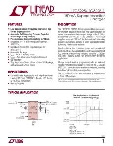
TYPE 8-1/8-1T Elastomer O-Ring Seals Basic Pressure Ratings Pressure (psig) 400
Pressure (bar g) 28
350
24
300
21
250
17
200
14
150
10
100
7
50
4
Type 8-1 Carbon vs. Silicon Carbide (1800 rpm) Type 8-1 Carbon vs. Silicon Carbide (3600 rpm) Type 8-1T Carbon vs. Silicon Carbide (1800 rpm) Type 8-1T Carbon vs. Silicon Carbide (3600 rpm)
0
1
2
3
0
25
52
76
4
(inches)
102 (mm)
Seal Size The Basic Pressure Rating is for a standard Type 8-1 or 8-1T seal, as shown in the typical arrangement, when installed according to the criteria given in this data sheet and generally accepted industrial practices. The Basic Pressure Rating assumes stable operation at 3600 rpm in a clean, cool, lubricating, nonvolatile liquid, with an adequate flush rate. When used with the Multiplier Factors, the Basic Pressure Rating can be adjusted to provide a conservative estimate of the dynamic pressure rating. For process services outside this range or a more precise assessment of the dynamic pressure rating, contact John Crane for more information.
Multiplier Factors
Selection Considerations
Multiplier Factor
Speed
Up to 3600 rpm Above 3600 rpm*
x 1.00 **
Sealed Fluid Lubricity
Gasoline, Kerosene or better Aqueous Solutions
x 1.00 x 0.75
Sealed Fluid Temperature (for carbon only)
Below 80°C/175°F From 80°C to 120°C/175°F to 250°F From 120°C to 180°C/250°F to 350°F Above 180°C/350°F
x x x x
* Not to exceed 25m/s/5000 fpm. ** Multiplier = 3600/new speed Example: If new speed = 4000 rpm Multiplier = 3600/4000 = 0.90
1.00 0.90 0.80 0.65
Example for Determining Pressure Rating Limits Seal: 50mm/2" diameter Type 8-1 Product: Water Face Material: Carbon vs. Silicon Carbide Temperature: 16°C/60°F Speed: 3600 rpm Using the Basic Pressure Rating chart the maximum pressure would be 17.25 bar g/250 psig. From the Multiplier Factors chart apply the multipliers for the specific service requirements to determine the maximum operating pressure for the application. 17.25 bar g/250 psig x 0.75 x 1.00 x 1.00 = 188 psig/13 bar g The maximum operating pressure of this 50mm/ 2" diameter Type 8-1 seal is 188 psig/13 bar g.
CUT LINE FOR SHORT PAGE
0
0
To determine the maximum pressure for a Type 8-1 or 8-1T, multiply the maximum pressure by the Multiplier Factors to obtain the maximum operating pressure.
TYPE 8-1/8-1T Elastomer O-Ring Seals Elastomer Temperature Limits Compound
Temperature
Nitrile
-40˚C to 120˚C / -40˚F to 250˚F
Fluorocarbon
-29˚C to 205˚C / -20˚F to 400˚F
(°C) –70
–20
40
100
150
200
250
(°F) –100
0
100
200
300
400
500
Ethylene Propylene -40˚C to 149˚C / -40˚F to 300˚F Neoprene®
-40˚C to 100˚C / -40˚F to 212˚F
Perfluoroelastomer -25˚C to 260˚C / -13˚F to 500˚F
CUT LINE FOR SHORT PAGE
Aflas®
-30˚C to 205˚C / -20˚F to 400˚F
Criteria for Installation Shaft/Sleeve
Limits
Surface Finish (max.)
0.8µm/32 Ra
Ovality/Out of Roundness (Shaft)
0.051mm/0.002"
End Play/Axial Float Allowance
±0.13mm/0.005"
TYPE 8-1/8-1T Elastomer O-Ring Seals Materials of Construction SEAL COMPONENTS
MATERIALS
Description
Standard
Options
Face/Primary Ring
Carbon
Carbon (Nuclear Service) Carbon Severe (Chemical Service) Nickel Binder Tungsten Carbide Silicon Carbide
O-Ring
Fluorocarbon
Aflas® Ethylene Propylene Neoprene® Nitrile Perfluoroelastomer
Disc Set Screws Retainer Snap Ring Springs
316 Stainless Steel
Alloy 400 (Monel®) Alloy 20 Cb-3 Hastelloy B® Alloy C-276 Titanium
Anti-X-Ring
PTFE
—
Aflas is a registered trademark of Asashi Glass Co. Ltd. Hastelloy B is a registered trademark of Hayes International. Monel is a registered trademark of Inco Alloys International, Inc. Neoprene is a registered trademark of DuPont Dow.
Europe Slough, UK
Latin America São Paulo, Brazil
Middle East, Africa, Asia Dubai, United Arab Emirates
North America Morton Grove, Illinois USA
Tel: 44-1753-224000 Fax: 44-1753-224224
Tel: 55-11-3371-2500 Fax: 55-11-3371-2599
Tel: 971-4-3438940 Fax: 971-4-3438970
1-800-SEALING Tel: 1-847-967-2400 Fax: 1-847-967-3915
For your nearest John Crane facility, please contact one of the locations above. If the products featured will be used in a potentially dangerous and/or hazardous process, your John Crane representative should be consulted prior to their selection and use. In the interest of continuous development, John Crane Companies reserve the right to alter designs and specifications without prior notice. It is dangerous to smoke while handling products made from PTFE. Old and new PTFE products must not be incinerated. ©2004 John Crane Inc. Print 2/04
www.johncrane.com
ISO 9001, ISO 14001, ISO/TS 16949 Certified.
S-8-1/8-1T