FFI-rapport 2010/00411
LYBIN 6.0 – test report
Morten Bosseng, Elin Dombestein and Amund Gjersøe
Forsvarets forskningsinstitutt/Norwegian Defence Research Establishment (FFI) 15 February 2010
FFI-rapport 2010/00411 356901
P: ISBN 978-82-464-1706-6 E: ISBN 978-82-464-1707-3
Keywords Akustisk deteksjon Modellering og simulering Programmering (Databehandling)
Approved by Connie Elise Solberg
Project Manager
Elling Tveit
Director of Research
Jan Erik Torp
Director
2
FFI-rapport 2010/00411
English summary The acoustic ray trace model LYBIN is a well established and frequently used sonar prediction model owned by the Norwegian Defence Logistic Organisation. The model is used aboard navy vessels as well as in training situations on shore. LYBIN has become an important tool in both planning and evaluation of maritime operations, and earlier versions are already integrated in combat system software, tactical decision aids and tactical trainers. The calculation kernel of LYBIN is now implemented as a software module called LybinCom. In addition there exists a graphical user interface which is used together with LybinCom to build a stand alone executive application. We call this application LYBIN. LybinCom has two different interfaces for data exchange with other software. The two interfaces are the binary interface and the eXtensible Markup Language (XML) interface. The binary interface enables fast transportation of large amounts of data to and from LybinCom. The XML interface is not as fast, but is more robust because the format of the input files is not as strict. The XML interface discards any parts of the input file it does not recognize. On behalf of NDLO, the Norwegian Defence Research Institute (FFI) has been responsible for testing, evaluation and further development of LYBIN since the year 2000. During this period, two new versions of LYBIN have been released. LYBIN 6.0 was released in august 2009. This document is a test report for LYBIN 6.0. Most functional requirements to LYBIN 6.0 are tested well. When it comes to non-functional requirements, some of the requirements are not tested or excluded from scope. In addition, extensive verification tests are run through both interfaces. These are programmed in C#. Some areas related to performance, value ranges and error handling should be further tested.
FFI-rapport 2010/00411
3
Sammendrag Den akustiske strålegangsmodellen LYBIN er en etablert og mye brukt sonar ytelsesmodell som eies av Forsvarets Logistikkorganisasjon. Modellen brukes både ombord på marinefartøy og i treningssituasjoner på land. LYBIN er blitt et viktig verktøy både i planlegging og evaluering av maritime operasjoner, og tidligere versjoner er allerede integrert i programvare for kampsystem, taktisk beslutningsstøtte og taktiske trenere. LYBINs beregningskjerne er nå implementert som en softwaremodul kalt LybinCom. I tillegg eksisterer det et grafisk brukergrensesnitt som sammen med LybinCom brukes for å bygge en frittstående eksekverbar applikasjon. Vi kaller denne frittstående applikasjonen for LYBIN. LybinCom har to ulike grensesnitt for datautveksling med annen programvare. De to grensesnittene er det binære grensesnittet og eXtensible Markup Language (XML) grensesnittet. Det binære grensesnittet muliggjør rask transport av store mengder data til og fra LybinCom. XML grensesnittet er ikke like raskt, men er mer robust fordi formatet til inputfilene ikke er så rigid. XML grensesnittet forkaster de delene av inputfila det ikke gjenkjenner. FFI har på vegne av FLO vært ansvarlig for test, evaluering og videreutvikling av LYBIN siden år 2000. I løpet av denne perioden har to nye versjoner blitt utgitt. LYBIN 6.0 ble utgitt i august 2009. Dette dokumentet er en testrapport for LYBIN 6.0. De fleste funksjonelle systemkrav til LYBIN 6.0 er testet godt. Når det gjelder ikke-funksjonelle krav er det ikke like god dekningsgrad. Omfattende verifikasjonstesting programmert i C# er gjennomført via begge grensesnitt. Områder relatert til ytelse, verdiområder og feilhåndtering bør testes videre.
4
FFI-rapport 2010/00411
Contents
1
Introduction
7
2
Overview of LYBIN 6.0
8
2.1
Making the application architecture
8
2.1.1
Use Cases
8
2.1.2
The application architecture of LYBIN 6.0
9
2.2
Implemented changes
11
2.3
How it will be used
13
3
Requirements
14
3.1
Functional requirements
14
3.2
Non-functional requirements
15
4
Test items
16
5
Test procedure
17
5.1
The process
17
5.2
The test cases
18
6
Test evaluation
18
6.1
Overall test evaluation
18
6.2
Detailed test evaluation per test item
18
6.2.1
Range dependent calculations
18
6.2.2
Precipitation
18
6.2.3
Calculations for passive sonar
19
6.2.4
Calculation of impulse response from a given point in the water volume
19
6.2.5
Calculation of travel time
19
6.2.6
New bottom loss model
19
6.2.7
Availability of results through binary and XML interface
19
6.2.8
Functions available through the binary and XML interface
19
6.2.9
The GUI
19
6.2.10
Improvement of reverberation algorithms
19
6.2.11
Denomination “dB” on all result data from LYBIN
20
6.2.12
Modification of format on message
20
6.2.13
Error handling
20
6.2.14
The binary interface
20
6.2.15
The XML interface
20
FFI-rapport 2010/00411
5
6.2.16
Security
20
6.3
Uncovered requirements
20
6.4
Areas not fully tested
21
7
Conclusion
21
References
22
Abbreviations
23
Appendix A Test cases
24
A.1
Input to the binary interface
24
A.1.1
Input parameters
24
A.1.2
Input environment dataset
36
A.2
Verification of result data via the binary interface
47
A.3
Comparison of parameters used via the binary interface versus via the XML interface
A.4
50
Comparison of result data via the binary interface versus via the XML interface
A.5
51
Comparison of result data from LYBIN 6.0 versus result data from LYBIN 4.0
55
A.6
GUI testing
58
A.6.1
First look
58
A.6.2
Setting parameters
59
A.6.3
Printing
60
A.6.4
NATO Bathy Message
60
A.6.5
View
60
A.6.6
Sonar self-noise
61
A.6.7
Environment Editor
62
A.6.8
Wind speed editor
63
A.6.9
Sound Speed editor
63
A.6.10
Bottom profile Editor
64
A.6.11
Bottom Type Editor
65
A.6.12
Bottom Loss Editor
65
A.6.13
Reverberation and noise Editor
66
A.6.14
Volume back scattering Editor
66
A.6.15
Bottom back scattering Editor
67
6
FFI-rapport 2010/00411
1
Introduction
The acoustic ray trace model LYBIN is a well established and frequently used sonar prediction model owned by the Norwegian Defence Logistic Organisation (NDLO). LYBIN is a range dependent two-dimensional model. A detailed description of the model is given in [1]. On behalf of NDLO, the Norwegian Defence Research Institute (FFI) has been responsible for testing, evaluation and further development of LYBIN since the year 2000. During this period, two new versions of LYBIN have been released. LYBIN 6.0 was released in august 2009. This document is a test report for LYBIN 6.0. LYBIN 6.0 is implemented as a COM module (LybinCom) for the windows platform. In addition there is a graphical user interface (GUI) which is used together with LybinCom in order to build a stand-alone application. This GUI is totally redone; it is programmed in C# and new functionality regarding range-dependency is added. The COM module enables LYBIN to interact with other applications, such as mathematical models, web services, geographical information systems and more. The COM module has two different interfaces for data exchange. The two interfaces are the binary interface and the eXtensible Markup Language (XML) interface. The interfaces are described in detail in [2] and [3]. The purpose of this test report is to give a quality evaluation of LYBIN 6.0. Chapter 2 gives a short overview of the product. Chapter 3 lists requirements derived from the project agreement [4]. Chapter 4 lists the test items derived from the requirements and those which emerged during the development period. Chapter 5 gives a brief description of the test process and chapter 6 gives an evaluation of the quality by describing the testing performed on each test item. Chapter 7 concludes with lessons learned and recommendations for further testing. An appendix describing the test cases used in LYBIN 6.0 testing ends this document.
FFI-rapport 2010/00411
7
2
Overview of LYBIN 6.0
2.1
Making the application architecture
Application architecture is the process of evaluating how to develop the application to meet the user's functional needs, while following a defined structure. If done right, we can achieve a maintainable and expandable application by defining the application architecture. 2.1.1
Use Cases
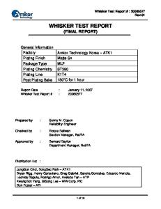
The architecture of LYBIN 6.0 is based on a Use Case model of the application, displayed in Figure 2.1. The Use Case model defines roles and use cases to help architects and developers to understand what type of roles the application is communicating with. The model also defines the different roles to perform in the application. uc Primary Use Cases Lybin 6.0
Load input data Load complete input model
Compute ray trace
Analyst Sav e complete model Edit input data
Generate NATO Bathy message
NATO message sender
Figure 2.1 Use Case model for LYBIN 6.0 We have defined two different user roles for LYBIN: the analyst and the NATO message sender. The analyst is the most common user role where LYBIN is used to compute raytraces. To be able to compute, the role needs functionality to load or manually input data. The results must be displayed on the screen. The user must also be able to save the input data used in computations. 8
FFI-rapport 2010/00411
The NATO message sender is a role where an officer wants to convert a sound speed profile to a defined NATO Bathy message format. 2.1.2
The application architecture of LYBIN 6.0
LYBIN 6.0 has a three layered architecture divided in the presentation-, domain- and data access layer. We group classes that are related in packages, and display them as shown in Figure 2.2. pkg Archtecture
Presentation Layer AnalystViews
NatoMessageSenderViews
Domain Layer Interfaces
Lybin Results Model
«Add-on» Components:: NatoMessageCreator
Lybin Data Model «COM» Components::LybinCom v6.0
DataAccess Layer Data Access
Figure 2.2 Package model of the LYBIN 6.0 architecture The packages of classes assumed to be needed is as follows: - AnalystViews: contains the user interfaces, and is dependent on the Lybin Data Model and the Lybin Results Model.
FFI-rapport 2010/00411
9
-
-
-
NatoMessageSenderViews is totally separated from the rest of LYBIN, and is thus defined as a loose component to LYBIN 6.0 through its dependency to the NatoMessageCreator. Lybin Data Model is a package containing the input data to the LYBIN calculation. It implements interfaces defined in the Interfaces-package, and depends on LybinCom. Lybin Results Model is a package containing the result data from a LYBIN calculation. It implements interfaces defined in the Interfaces-package, and depends on the Lybin Data Model package. Interface is a package of interfaces used for polymorphism. NatoMessageCreator is a component that is an optional add-on to LYBIN 6.0. LybinCom v6.0 is a component which is vital for LYBIN 6.0 Data Service Layer is a package containing classes for mapping data from a file format to the Lybin Data Model, and depends on the Lybin Data Model package.
cmp Components
Lybin 6.0
«COM» LybinCom v6.0 «delegate»
Interop.LybinCom
ILybinModelComBin
ILybinModelComBin
«delegate»
Lybin GUI
ILybinModelCom
ILybinModelCom
«delegate» IModelData
IModelData
«delegate» IPlatform
«delegate»
ISensor
IPlatform
ISensor «delegate»
IPuls
IPuls «delegate»
LybinDataModel
IEnvironment «delegate»
«Add-on» NatoMessageCreator
IEnvironment
IOcean
IOcean
Written in .NET (Managed memory)
Written in C++ (Unmanaged memory)
Figure 2.3 Component model of LYBIN 6.0 LYBIN 6.0 is developed in two different environments: C#.NET with managed memory, and C++ with unmanaged memory. This is due to legacy and efficiency. LybinCom is legacy code developed and maintained in C++. C#.NET increases the developer's progress, but is not as efficient when performing calculations. Thus Lybin's combination of C++ and C# is reasonable.
10
FFI-rapport 2010/00411
As displayed in Figure 2.3, LYBIN 6.0 is a component dependent on LybinCom. LYBIN 6.0 contains the main parts of a user interface component called LYBIN GUI, a domain model component called LybinDataModel, and a .NET wrapper for the COM called Interop.LybinCom. LybinCom defined as a COM with a set of interfaces. This enables other developers to implement LybinCom independent of the graphical user interface delivered by LYBIN 6.0. NatoMessageCreator is a component automatically detected and used by LYBIN 6.0 if installed. 2.2
Implemented changes
The graphical user interface (GUI) is totally rebuilt to LYBIN 6.0. A detailed description of all new functionality is out of scope for this document, but a brief introduction is provided here to give an impression of the test effort. The editors now use data grid views from .NET and data binding linked to these. Property grids from .NET are also used in input parameter setting. Figure 2.4 gives an overview of the new GUI.
Figure 2.4 An overview of the new GUI. More parameters to control the display of plots are added in a new tab. Figure 2.5 gives an overview of the new tab for display parameters.
FFI-rapport 2010/00411
11
Figure 2.5 An overview of the new Display tab. A new Environment plot is added. In addition to display this plot in a tab next to the Settings tab, a dedicated editor is implemented. The editor gives possibilities to visualize environment input parameters varying over a distance. The editor is displayed in Figure 2.6. Here the variation in wind speed is given by the wave height, the variation in sound speed is given by the colours and the variation in bottom type is displayed with shades of grey.
Figure 2.6 The Environment Editor. All editors have been changed to use standard .NET forms components. However, additional changes have been performed on some editors. One worth mentioned here is the new Sound Speed Profile Editor. The new version of this editor supports range dependent input of sound speed profiles. In addition, a visualisation of the profile is included. If files in format “edf” are
12
FFI-rapport 2010/00411
imported, information about where the bathy drop has taken place will be displayed. The new editor is displayed in Figure 2.7.
Figure 2.7 The Sound Speed Profile Editor in LYBIN 6.0. The entering of parameters is adjusted to fit standard GUI components. Figure 2.8 gives an example.
Figure 2.8 An example displaying how input of several values is solved in LYBIN 6.0. 2.3
How it will be used
LYBIN is an acoustic ray tracing software widely used by the Norwegian Navy for sonar performance prediction. It is a stand alone executive application with a graphical user interface to interact with the calculation kernel and to display calculation results [5].
FFI-rapport 2010/00411
13
The calculation kernel of LYBIN, LybinCom, is implemented as a COM module for the windows platform in order to ease the integration with other applications such as weapons systems, training simulators and planning tools. The military employment of LYBIN adds stringent demands to the software regarding hardening settings.
3
Requirements
The following requirements to new functionality were identified to LYBIN 6.0. These are requirements that are derived from the Project Agreement document [6]. 3.1
Functional requirements
Functional Requirements describe the features, behaviour, business rules and general functionality that the new release must support. Input requirements Range dependent bottom type Range dependent sound speed Range dependent wind speed Calculation requirements Calculation of detection range for passive sonar. Calculation of beam travel time. Calculation of impulse response. Possibility to take precipitation into account in the calculations Calculation of range dependent thermal loss Output requirements The calculated travel time shall be available on binary format. The calculated impulse response shall be available on binary format. It should be possible to define which result data that is going to be returned from LYBIN. User Interface requirements The GUI shall handle range dependent data input and visualization. Business rules requirements The reverberation algorithms shall be improved. Tests have shown that the error can be up to 10 dB in some cases, this error will be corrected. Result data returned from LYBIN shall be given in decibel. To improve the calculation time over consecutive runs, LYBIN will have internal memory so only parameters that differs from the previous run is needed as input.
14
FFI-rapport 2010/00411
3.2
A new model for calculation of bottom loss, valid for frequencies bellow 1 kHz, will be included. Non-functional requirements
The non-functional requirements typically describe performance criteria, reliability, security and other operational parameters. Performance The response time for the existing functions in LYBIN 4.0 shall not be extended in LYBIN 6.0. Extendibility It should be easy to extend functionality for treatment of existing result data. It should be easy to retrieve new result data It should be easy for other GUIs or applications to link to the kernel. Security LYBIN shall run without any error under NSM’s server hardening settings. The hardening settings are described in [7]. A security assessment from project P6344 – Ula Class Sonar Upgrade is given in [8]. Documents The following documents shall be written: An interface document describing the interface and how to integrate LYBIN into a thirdparty solution. A user manual describing functionality accessed from the LYBIN GUI. A test report documenting the quality of the software. A test plan with test cases.
FFI-rapport 2010/00411
15
4
Test items
Some requirements were postponed and some were added during the development period. In addition, more thorough testing of existing functionality was performed to ensure good quality. No structured system test of functionality was performed on the previous releases. The project therefore spent effort on testing the COM-module through the interfaces and through the graphical user interface (GUI). The GUI was totally rebuilt with C# to LYBIN 6.0. This resulted in a major part of the test effort had to be performed on the GUI. But by accessing LYBIN through the GUI, a lot of other test items were tested as well. The following test items were identified in the test plan[9] and during the development period: Range dependent calculations. Taking precipitation into account. Calculations for passive sonar. Calculation of impulse response from a given point in the water volume. Calculation of beam travel time. Transmission loss related to passive calculations. New bottom loss model. Availability of all results on binary and xml format. Functions available through the binary and the xml interface. Full test of the GUI. Improvement of reverberation algorithms. Denomination “dB” on all result data from LYBIN. Modification of format on message. Error handling. Printing from GUI. Flags which indicate how bottom reverberation and bottom loss is calculated. New type of result data: Ambient Noise. Binary interface. Xml interface. Choice whether to use wave height or wind speed. The following was excluded from the 6.0 scope: Implementation of control switches to control which calculations to be performed. Help functionality in GUI. Save results from GUI.
16
FFI-rapport 2010/00411
5
Test procedure
5.1
The process
Much effort was spent on setting up test cases in Visual Studio 2008 Test Edition[10]. This was done to form a basis of test cases to be run for all releases in the future. When updates were done in the code, these programmed test cases were run to ensure that existing functionality did not break. A clean run of the test cases indicates that the code has good quality and may be ready to be released to the customer. Some time was also used on studying test planning. There are several internet sites covering the subject. The book “Software Testing with Visual Studio Team System 2008” [11] gave good help during the implementation of the tests. White-box testing was performed by the developers while they were implementing new functionality. A dedicated test resource performed black-box testing with the programmed test cases. In addition, some in-house resources were given access to a beta-version of the product for testing. An excel-sheet [12] was used to control the test process. The sheet had the following columns: ID Area Description Responsible Status Severity Comments/rev history Created by Date created All found errors (defects) were inserted as rows in the sheet with product owner set as the responsible. The defect was then distributed to the appropriate developer. All comments or actions performed by the project members were noted in the column for comments along with date and resource id. This sheet will of course be helpful when this test report is written, but also in later releases when one tries to understand why a problem solution was chosen. A simple excel sheet was chosen over a bug-tracking tool due to the fact that the project has a small number of resources and did not prioritize to use the time to implement such a tool.
FFI-rapport 2010/00411
17
5.2
The test cases
Test cases that have been run on to the release of LYBIN 6.0 are described in Appendix A. Some test cases are programmed, but some are manual test cases that have to be run by a user through the LYBIN GUI.
6
Test evaluation
6.1
Overall test evaluation
The testing has focused on functionality and that the correct data is included in the calculations. Some inspection is performed on the result data but further testing should be performed here to ensure that they are correct. The binary interface has been tested with many test cases. The quality is good when it comes to functionality. A beta version of the product was also released to in-house users and they have accessed LybinCom through the binary interface via Matlab [13]. Some problems linked to the XML interface have been discovered. The problems were solved close up to the release, and some high-level testing has been performed. However, this area is not as well tested as the access through the binary interface. High-level tests on sending input parameters over the XML interface have been performed. Returning results as XML are thoroughly tested. The LYBIN GUI is totally rebuilt. In addition to implementation and testing, much effort has been spent on evaluating how to implement functionality. This area has gone through extensively testing compared to other test areas. However, the editors in the GUI could have been tested further and there may still be errors especially linked to range dependent input requirements. 6.2 6.2.1
Detailed test evaluation per test item Range dependent calculations
The functionality is tested through the GUI and with programmed test cases through the binary interface. The code is stepped through and the resulting plots are visually checked for abnormal changes of gradients and values. Range dependent sound velocity profiles are also used and compared to measured data in [14] and [15]. 6.2.2
Precipitation
The implemented code for this new functionality is implemented in Matlab[13] as well. Plots are visually analyzed to ensure that the energy loss due to precipitation corresponds with the expected loss for various frequencies.
18
FFI-rapport 2010/00411
6.2.3
Calculations for passive sonar
The implementation of calculations for passive sonar is thoroughly described in [16]. Tests are run that ensure that passive sonar parameters are used in the calculation. Tests are also run from Matlab[13]. A sonar processing chain for passive calculations is prepared in Matlab and the results are compared with the processing chain in LYBIN 6.0. 6.2.4
Calculation of impulse response from a given point in the water volume
The results are compared to the results from an impulse response prototype. Calculated impulse response is also compared with simple analytical solutions in some cases. 6.2.5
Calculation of travel time
This test item is tested with constant sound velocity. The travel time result data is analyzed and calculations are performed to come back to the sound velocity. The results are also compared to the results from a beam travel time calculating prototype. 6.2.6
New bottom loss model
The new bottom loss model was first implemented in Matlab [13], where the calculated bottom loss values were compared with the correct analytical solution. The bottom loss model was then written into C++ code and included in LYBIN. The new bottom loss model in LYBIN is tested by comparisons of calculated transmission loss with reference solutions including both single and multiple bottom hits. 6.2.7
Availability of results through binary and XML interface
Most results are available through both interfaces. The new result data AMBIENTNOISELEVELUSED [2] is available through both interfaces. Impulse response and beam travel time are not available through the XML interface. 6.2.8
Functions available through the binary and XML interface
All functions described in [2] are available through the binary interface. However, there are only general functions for model update and result retrieval available through the XML interface. 6.2.9
The GUI
The LYBIN GUI is totally rebuilt. In addition to implementation and testing, much effort has been spent on evaluating how to implement functionality. This area has gone through extensively testing compared to other test areas. However, the editors in the GUI could have been tested further and there may still be errors especially linked to range dependent input requirements 6.2.10
Improvement of reverberation algorithms
The improvements are tested versus test cases described in [17].
FFI-rapport 2010/00411
19
6.2.11
Denomination “dB” on all result data from LYBIN
All result data are visually analyzed and run through some high-level programmed checks. The calculated transmission loss included in the impulse response calculations is not given in decibels, due to the costumer’s request. 6.2.12
Modification of format on message
The NATO Bathy message creator is an add-on to LYBIN 6.0, giving LYBIN functionality to create a NATO Bathy message. This has been written according to ATP32 (D) [18]. The feedback from the customer, after evaluating the functionality, has resulted in a change in the NATO Bathy message functionality to be rewritten according to ATD32 (C) [19]. 6.2.13
Error handling
This has been an ongoing activity while the product has been developed. The error handling from the GUI has been greatly improved. Errors occurring in the kernel of LybinCom are normally suppressed, and the calculation results will be empty. Improvements in error handling in LybinCom concern the information sent through the COM interface. Now, when trying to fetch empty results, a COMException is thrown along with a message: "No data available". In addition, some basic error information is sent over the COM interface when the XML-parser is unable to read a xml-string sent through ChangeModelData[2], and if some basic input parameters are invalid when trying to run DoCalculation[2]. 6.2.14
The binary interface
This interface has been thoroughly tested. 6.2.15
The XML interface
High-level tests on sending input parameters over the XML interface have been performed. Returning results as XML are thoroughly tested. 6.2.16
Security
High-level tests are run on a virtual pc set up with the NSM hardening settings [7]. 6.3
Uncovered requirements
Most functional requirements are covered. When it comes to non-functional requirements, some of the requirements are not tested or omitted. The response time for existing functions in LYBIN 4.0 has not been tested. However, the added functionality in the new release have been mostly added as new functions and not implemented in existing code. In addition, efficiency improvements are implemented in the existing code. We therefore believe that the response times have not been heavily affected. Documents listed in the non-functional requirements are produced. One document that is not yet released is the GUI user manual. This document will be released the spring og 2010. 20
FFI-rapport 2010/00411
The document describing the XML interface, [3], is obsolete to LYBIN 6.0. Our goal is to write a new description of this interface within the next release. This description is also planned to contain more extensive descriptions of how to access the XML interface. 6.4
Areas not fully tested
More extensive testing of result data was originally planned in the following areas: Comparison of result data with similar result data in the previous release. More extensive testing of setting input through the XML interface. Performance tests Tests of the valid value range of input parameters have not been performed on either interfaces. Tests verifying correct exception handling for invalid values on input parameters have not been fully performed on either interface. Validation of calculation results with other models and real measurements.
7
Conclusion
On behalf of NDLO, the Norwegian Defence Research Institute (FFI) has been responsible for testing, evaluation and further development of LYBIN since the year 2000. During this period, two new versions of LYBIN have been released. LYBIN 6.0 was released in august 2009. The purpose of this report is to give a quality evaluation of LYBIN 6.0 Most functional requirements to LYBIN 6.0 are tested well. When it comes to non-functional requirements, some of the requirements are not tested or excluded from scope. In addition, extensive verification tests are run through both interfaces. These are programmed in C#. Some areas related to data quality, performance, value ranges and error handling should be further tested. These are described in Section 6.4. In addition other testing should be considered: Send the new release to NURC for testing. NURC have run comparisons with other models before. This is described in [20]. Get an overview over the different coding languages/environments used to access LybinCom. Set up test cases for these and run them. Analyze defects found after release, learn from them and build automated test cases to avoid them in the future. Since the LYBIN GUI is new to LYBIN 6.0, more detailed testing of the various editors should be considered.
FFI-rapport 2010/00411
21
References [1] S. Mjølsnes, "LYBIN SGP-180(C) - Model Description," The Royal Norwegian Navy Materiel Command, Bergen,2000. [2] E. Dombestein, A. L. Gjersøe, and M. Bosseng, "LybinCom 6.0 - description of the binary interface,"2009/00188, 2009. [3] E. Dombestein and S. Alsterberg, "LYBIN XML grensesnitt versjon 1," FFI Rapport 2006/00266, 2006. [4]
"Oppdragsavtale mellom FFI og FLO angående "Videreutvikling av LYBIN", Kontraktsnr. 4500114743," Project agreement Oct.2008.
[5] K. T. Hjelmervik, S. Mjølsnes, E. M. Dombestein, T. S. Såstad, and J. Wegge, "The acoustic raytrace model Lybin - Description and applications, UDT 2008," 2008. [6]
"Oppdragsavtale mellom FFI og FLO angående "Videreutvikling av LYBIN", Kontraktsnr. 4500114743," Project agreement Oct.2008.
[7] Nasjonal sikkerhetsmyndighet, "Baseline SCE settings for W2003/XP,"2006. [8] KONGSBERG DEFENCE & AEROSPACE AS, "P6344 . Ula Class Sonar Upgrade, Security Assessment Document," BEGRENSET 2008. [9] M. Bosseng, "LYBIN 6.0 - test plan," Internal working document 2009. [10]
"msdn.microsoft.com," 2009.
[11] S. Subashni and K. N Satheesh, Software Testing with Visual Studio Team System 2008 2008. [12]
"LYBIN 6.0 - issues document," Internal working document 2009.
[13]
"www.mathworks.com," 2008.
[14] P. Østenstad, "Oseanografiske variasjoner i testområde for KNM Fridtjof Nansens akseptansetester, mars 2007," FFI Rapport 2007/01313, 2007. [15] H. S. Olsen, "Lydutbredelse i havområder med avstandsavhengig oseanografi," Masteroppgave 2008. [16] S. Alsterberg and E. Dombestein, "Software specification of passive sonar calculations in LYBIN 4.0," FFI Rapport 2005/03388, 2005. [17] M. Collin, M. Ainslie, and R. v. Vossen, "Rumble 2: Technical Report on the Selection of the Forward Model (DE04),"2009. [18]
"ATP 32(D) Navy - NATO handbook of military oceanographic information services,"2008/01457, 2008.
22
FFI-rapport 2010/00411
[19]
"ATP 32(C) Navy - Nato handbook of military oceanographic information services,"2005/03950, 1999.
[20] S. M. Ferla, C. Isoppo, G. Martinelli, and F. B. Jensen, "Performance assessment of the LYBIN-2.0 propagation model, SACLANTCEN SM-384,"2001.
Abbreviations FFI NDLO LYBIN XML COM
FFI-rapport 2010/00411
Norwegian Defense Research Institute Norwegian Defense Logistic Organization LYdBane og INtensitetsprogram (acoustic model) Extensible Markup Language Component Object Model
23
Appendix A
Test cases
This appendix describes the test cases which were used for testing of the LYBIN 6.0 release. Most tests will be programmed and run via Visual Studio 2008 [10]. But some tests was run manually and via other software (e.g. Matlab [13]). A.1
Input to the binary interface
The tests in this chapter verify that parameters and input dataset can be set programmatically from C# code through the binary interface. XML is collected from LybinCom by running GetResultModelData before and after parameters are set. A.1.1
Input parameters
Description
Expected result
Calculation Swithches a) Create an instance of LybinModelComBinClass. b) Collect XML with GetResultModel (startXML). c) Set parameter BottomReverberationCalculation to false. d) Run calculation. e) Collect XML with GetResultModel (actualXML). f) Compare the two XMLs. g) Collect the value from the actualXML and compare it with the default value. h) Repeat a) – g) for: - ProbabilityOfDetectionCalculation - RayTraceCalculation - SignalExcessCalculation - SurfaceReverberationCalculation - TransmissionLossFromTargetCalculation - TransmissionLossToTargetCalculation - VolumeReverberationCalculation
The two XMLs shall not be equal. Only the altered value shall be changed.
DepthCells a) Create an instance of LybinModelComBinClass. b) Collect XML with GetResultModel (startXML). c) Call SetDepthScaleAndDepthCells with parameters 100 and 20.
The two XMLs shall not be equal. Only the altered value shall be changed, they shall be equal when the value is set back to default. The value for DepthCellSize should be 5.0 and the value for DepthSteps should be 400.
24
FFI-rapport 2010/00411
d) Run calculation. e) Collect XML with GetResultModel (actualXML). f) Compare the two XMLs. DepthCellSize-1 a) Create an instance of LybinModelComBinClass. b) Collect XML with GetResultModel (startXML). c) Call SetDepthScaleAndDepthCellSize with parameters 100 and 5. d) Run calculation. e) Collect XML with GetResultModel (actualXML). f) Compare the two XMLs.
The two XMLs shall not be equal. Only the altered value shall be changed, they shall be equal when the value is set back to default. The value for DepthCells should be 20 and the value for DepthSteps should be 400.
DepthCellSize-2 a) Create an instance of LybinModelComBinClass. b) Collect XML with GetResultModel (startXML). c) Call SetDepthCellSizeAndDepthSteps with parameters 5 and 400. d) Run calculation. e) Collect XML with GetResultModel (actualXML). f) Compare the two XMLs.
The two XMLs shall not be equal. Only the altered value shall be changed, they shall be equal when the value is set back to default. The value for DepthScale should be 100 and the value for DepthCells should be 20.
DepthScale a) Create an instance of LybinModelComBinClass. b) Collect XML with GetResultModel (startXML). c) Call SetDepthScaleAndDepthSteps with parameters 100 and 400. d) Run calculation. e) Collect XML with GetResultModel (actualXML). f) Compare the two XMLs.
The two XMLs shall not be equal. Only the altered value shall be changed, they shall be equal when the value is set back to default. The value for DepthCellSize should be 5 and the value for DepthCells should be 20.
DepthSteps This parameter is tested in the previous tests. The two XMLs shall not be equal. Only the altered value shall be changed, they shall be equal when the value is set back to default. The value for
DepthStepSize a) Create an instance of LybinModelComBinClass. b) Collect XML with GetResultModel
FFI-rapport 2010/00411
25
c) d) e) f)
(startXML). Call SetDepthScaleAndDepthSteps with parameters 100 and 400. Run calculation. Collect XML with GetResultModel (actualXML). Compare the two XMLs.
DepthStepSize should be 0,25.
ImpulseResponseCalculation a) Create an instance of LybinModelComBinClass. b) Collect XML with GetResultModel (startXML). c) Set parameter ImpulseResponseCalculation to true. d) Run calculation. e) Collect XML with GetResultModel (actualXML). f) Compare the two XMLs. g) Collect the value from the actualXML and compare it with the default value.
The two XMLs shall not be equal. Only the altered value shall be changed.
ImpulseResponseDepth a) Create an instance of LybinModelComBinClass. b) Collect XML with GetResultModel (startXML). c) Set parameter ImpulseResponseDepth to 99.0. d) Run calculation. e) Collect XML with GetResultModel (actualXML). f) Compare the two XMLs. g) Collect the value from the actualXML and compare it with the default value.
The two XMLs shall not be equal. Only the altered value shall be changed.
NoiseCalculation a) Create an instance of LybinModelComBinClass. b) Collect XML with GetResultModel (startXML). c) Set parameter NoiseCalculation to false. d) Run calculation. e) Collect XML with GetResultModel (actualXML). f) Compare the two XMLs.
The two XMLs shall not be equal. Only the altered value shall be changed.
26
FFI-rapport 2010/00411
g) Collect the value from the actualXML and compare it with the default value. PassiveCalculation a) Create an instance of LybinModelComBinClass. b) Collect XML with GetResultModel (startXML). c) Set parameter PassiveCalculation to true. d) Run calculation. e) Collect XML with GetResultModel (actualXML). f) Compare the two XMLs. g) Collect the value from the actualXML and compare it with the default value.
The two XMLs shall not be equal. Only the altered value shall be changed.
RangeCells a) Create an instance of LybinModelComBinClass. b) Collect XML with GetResultModel (startXML). c) Call SetRangeScaleAndRangeCells with parameters 100 and 20. d) Run calculation. e) Collect XML with GetResultModel (actualXML). f) Compare the two XMLs.
The two XMLs shall not be equal. Only the altered value shall be changed, they shall be equal when the value is set back to default. The value for RangeCellSize should be 5.0 and the value for RangeSteps should be 200.
RangeCellSize-1 a) Create an instance of LybinModelComBinClass. b) Collect XML with GetResultModel (startXML). c) Call SetRangeScaleAndRangeCellSize with parameters 100 and 5. d) Run calculation. e) Collect XML with GetResultModel (actualXML). f) Compare the two XMLs.
The two XMLs shall not be equal. Only the altered value shall be changed, they shall be equal when the value is set back to default. The value for RangeCells should be 20 and the value for RangeSteps should be 200.
RangeCellSize-2 a) Create an instance of LybinModelComBinClass. b) Collect XML with GetResultModel (startXML). c) Call SetRangeCellSizeAndRangeSteps with parameters 5 and 200.
The two XMLs shall not be equal. Only the altered value shall be changed, they shall be equal when the value is set back to default. The value for RangeScale should be 100 and the value for RangeCells should be 20.
FFI-rapport 2010/00411
27
d) Run calculation. e) Collect XML with GetResultModel (actualXML). f) Compare the two XMLs. RangeScale a) Create an instance of LybinModelComBinClass. b) Collect XML with GetResultModel (startXML). c) Call SetRangeScaleAndRangeSteps with parameters 100 and 200. d) Run calculation. e) Collect XML with GetResultModel (actualXML). f) Compare the two XMLs.
The two XMLs shall not be equal. Only the altered value shall be changed, they shall be equal when the value is set back to default. The value for DepthCellSize should be 5 and the value for DepthCells should be 20.
RangeSteps This parameter is tested in the previous tests. RangeStepSize a) Create an instance of LybinModelComBinClass. b) Collect XML with GetResultModel (startXML). c) Call SetRangeScaleAndRangeSteps with parameters 100 and 400. d) Run calculation. e) Collect XML with GetResultModel (actualXML). f) Compare the two XMLs.
The two XMLs shall not be equal. Only the altered value shall be changed, they shall be equal when the value is set back to default. The value for RangeStepSize should be 0,25.
TravelTimeAngleRes a) Create an instance of LybinModelComBinClass. b) Collect XML with GetResultModel (startXML). c) Set parameter TravelTimeAngleRes to 99.0. d) Run calculation. e) Collect XML with GetResultModel (actualXML). f) Compare the two XMLs. g) Collect the value from the actualXML and compare it with the default value.
The two XMLs shall not be equal. Only the altered value shall be changed.
TravelTimeCalculation a) Create an instance of LybinModelComBinClass.
The two XMLs shall not be equal. Only the altered value shall be changed.
28
FFI-rapport 2010/00411
b) Collect XML with GetResultModel (startXML). c) Set parameter TravelTimeCalculation to true. d) Run calculation. e) Collect XML with GetResultModel (actualXML). f) Compare the two XMLs. g) Collect the value from the actualXML and compare it with the default value. TypeOfRevNoiseCalculation-1 a) Create an instance of LybinModelComBinClass. b) Insert various bottom types over the range. c) Set parameter TypeOfRevNoiseCalculation to 1. d) Collect XML with GetResultModel (startXML). e) Run calculation. f) Collect XML with GetResultModel (actualXML). g) Compare the two XMLs.
TypeOfRevNoiseCalculation will be set to 0, since the value 1 indicates that a bottom back scatter dataset is available.
TypeOfRevNoiseCalculation-2 a) Create an instance of LybinModelComBinClass. b) Insert a bottom back scattering dataset. c) Set parameter TypeOfRevNoiseCalculation to 1. d) Collect XML with GetResultModel (startXML). e) Run calculation. f) Collect XML with GetResultModel (actualXML). g) Compare the two XMLs.
The two XMLs will be equal since the calculation switch is set to use the available bottom back scattering dataset.
TypeOfRevNoiseCalculation-3 a) Create an instance of LybinModelComBinClass. b) Insert a rev and noise dataset. c) Set parameter TypeOfRevNoiseCalculation to 0. d) Collect XML with GetResultModel (startXML). e) Run calculation. f) Collect XML with GetResultModel
TypeOfRevNoiseCalculation will still be set to 0. The inserted rev and noise dataset will be removed since it is not used in the calculation.
FFI-rapport 2010/00411
29
(actualXML). g) Inspect the actualXML TypeOfRevNoiseCalculation-4 a) Create an instance of LybinModelComBinClass. b) Insert a rev and noise dataset. c) Set parameter TypeOfRevNoiseCalculation to 2. d) Collect XML with GetResultModel (startXML). e) Run calculation. f) Collect XML with GetResultModel (actualXML). g) Compare the two XMLs.
TypeOfRevNoiseCalculation will still be set to 2. The inserted rev and noise dataset will still be present since the value 2 indicates that the rev and noise dataset is to be used.
UseMeasuredBottomLoss-1 a) Create an instance of LybinModelComBinClass. b) Insert a bottom loss dataset. c) Collect XML with GetResultModel (startXML). d) Run calculation. e) Collect XML with GetResultModel (actualXML). f) Inspect the actualXML
The bottom loss dataset will not be present since the parameter UseMeasuredBottomLoss is not set to true.
UseMeasuredBottomLoss-2 a) Create an instance of LybinModelComBinClass. b) Insert a bottom loss dataset. c) Set the parameter UseMeasuredBottomLoss to true. d) Collect XML with GetResultModel (startXML). e) Run calculation. f) Collect XML with GetResultModel (actualXML). g) Compare the two XMLs.
Both switch and dataset will be present in the actualXML.
UseRayleighBottomLoss-1 a) Create an instance of LybinModelComBinClass. b) Insert a Rayleigh bottom loss dataset. c) Collect XML with GetResultModel (startXML). d) Run calculation.
The Rayleigh bottom loss dataset will not be present since the parameter UseRayleighBottomLoss is not set to true.
30
FFI-rapport 2010/00411
e) Collect XML with GetResultModel (actualXML). f) Inspect the actualXML UseRayleighBottomLoss-2 a) Create an instance of LybinModelComBinClass. b) Insert a Rayleigh bottom loss dataset. c) Set the parameter UseRayleighBottomLoss to true. d) Collect XML with GetResultModel (startXML). e) Run calculation. f) Collect XML with GetResultModel (actualXML). g) Compare the two XMLs.
Both switch and dataset will be present in the actualXML.
UseRayleighBottomLoss-3 a) Create an instance of LybinModelComBinClass. b) Insert a Rayleigh bottom loss dataset. c) Set the parameter UseRayleighBottomLoss to true. h) Insert a bottom loss dataset. d) Set the parameter UseMeasuredBottomLoss to true. e) Collect XML with GetResultModel (startXML). f) Run calculation. g) Collect XML with GetResultModel (actualXML). h) Inspect the actualXML.
Both switch and dataset will be present in the actualXML. UseMeasuredBottomLoss is overridden by the rayleigh switch and will be set to false. The Bottom loss dataset will be removed.
VisualRayTraceCalculation a) Create an instance of LybinModelComBinClass. b) Collect XML with GetResultModel (startXML). c) Set parameter VisualRayTraceCalculation to true. d) Run calculation. e) Collect XML with GetResultModel (actualXML). f) Compare the two XMLs. g) Collect the value from the actualXML and compare it with the default value.
The two XMLs shall not be equal. Only the altered value shall be changed.
FFI-rapport 2010/00411
31
VisualSurfaceHits a) Create an instance of LybinModelComBinClass. b) Collect XML with GetResultModel (startXML). c) Set parameter VisualSurfaceHits to 99. d) Run calculation. e) Collect XML with GetResultModel (actualXML). f) Compare the two XMLs. g) Collect the value from the actualXML and compare it with the default value.
The two XMLs shall not be equal. Only the altered value shall be changed.
VisualBottomHits a) Create an instance of LybinModelComBinClass. b) Collect XML with GetResultModel (startXML). c) Set parameter VisualBottomHits to 99. d) Run calculation. e) Collect XML with GetResultModel (actualXML). f) Compare the two XMLs. g) Collect the value from the actualXML and compare it with the default value.
The two XMLs shall not be equal. Only the altered value shall be changed.
VisualNumRays a) Create an instance of LybinModelComBinClass. b) Collect XML with GetResultModel (startXML). c) Set parameter VisualNumRays to 99. d) Run calculation. e) Collect XML with GetResultModel (actualXML). f) Compare the two XMLs. g) Collect the value from the actualXML and compare it with the default value.
The two XMLs shall not be equal. Only the altered value shall be changed.
Other Model Parameters a) Create an instance of LybinModelComBinClass. b) Collect XML with GetResultModel (startXML). c) Set parameter MaxBorderHits to 99. d) Run calculation.
The two XMLs shall not be equal. Only the altered value shall be changed.
32
FFI-rapport 2010/00411
e) Collect XML with GetResultModel (actualXML). f) Compare the two XMLs. g) Collect the value from the actualXML and compare it with the default value. h) Repeat a) – g) for: - SignalExcessConstant - TerminationIntensity - TRLRays Simple Ocean properties a) Create an instance of LybinModelComBinClass. b) Collect XML with GetResultModel (startXML). c) Set parameter AmbientNoiseLevel to 99.0. d) Run calculation. e) Collect XML with GetResultModel (actualXML). f) Compare the two XMLs. g) Collect the value from the actualXML and compare it with the default value. h) Repeat a) – g) for: - PH - ShipDensity - SourceLevelTarget - SurfaceScatterFlag - TargetStrength - TargetSpeed
The two XMLs shall not be equal. Only the altered value shall be changed.
PrecipitationType a) Create an instance of LybinModelComBinClass. b) Collect XML with GetResultModel (startXML). c) Set parameter PrecipitationType to PrecipitationType.LightRain. d) Run calculation. e) Collect XML with GetResultModel (actualXML). f) Compare the two XMLs. g) Collect the value from the actualXML and compare it with the default value. h) Repeat the procedure for PrecipitationType.HeavyRain (2),
The two XMLs shall not be equal. Only the altered value shall be changed. The parameter should be set to 1, 2, 3 or 4.
FFI-rapport 2010/00411
33
Platform properties a) Create an instance of LybinModelComBinClass. b) Collect XML with GetResultModel (startXML). c) Set parameter Selfnoise to 99.0. d) Run calculation. e) Collect XML with GetResultModel (actualXML). f) Compare the two XMLs. g) Collect the value from the actualXML and compare it with the default value. h) Repeat step a) – g) for: - SelfNoisePassive - Speed
The two XMLs shall not be equal. Only the altered value shall be changed.
Sensor properties a) Create an instance of LybinModelComBinClass. b) Collect XML with GetResultModel (startXML). c) Set parameter BeamWidthReceiver to 99.0. d) Run calculation. e) Collect XML with GetResultModel (actualXML). f) Compare the two XMLs. g) Collect the value from the actualXML and compare it with the default value. h) Repeat step a) – g) for: - BeamWidthTransmitter - CalibrationFactor - Depth - DetectionThreshold - DirectivityIndex - Frequency - IntegrationTimePassive - PassiveBandWith - PassiveFrequency - SideLobeReceiver - SideLobeTransmitter - SonarTypePassive - SouceLevel
The two XMLs shall not be equal. Only the altered value shall be changed.
34
FFI-rapport 2010/00411
- SourceLevelPassive - SystemLoss - TiltReceiver - TiltTransmitter EnvelopeFunction a) Create an instance of LybinModelComBinClass. b) Collect XML with GetResultModel (startXML). c) Set parameter EnvelopeFunction to “test”. d) Run calculation. e) Collect XML with GetResultModel (actualXML). f) Compare the two XMLs. g) Collect the value from the actualXML and compare it with the default value.
The two XMLs shall be equal. Altering of this property should always give “hann”.
Other Pulse properties a) Create an instance of LybinModelComBinClass. b) Collect XML with GetResultModel (startXML). c) Set parameter FilterBandWidth to 99.0. d) Run calculation. e) Collect XML with GetResultModel (actualXML). f) Compare the two XMLs. g) Collect the value from the actualXML and compare it with the default value. h) Repeat step a) – g) for: - FMBandWidth - Length
The two XMLs shall not be equal. Only the altered value shall be changed.
Form a) Create an instance of LybinModelComBinClass. b) Collect XML with GetResultModel (startXML). c) Set parameter Form “test”. d) Run calculation. e) Collect XML with GetResultModel (actualXML). f) Compare the two XMLs. g) Collect the value from the actualXML and compare it with the default value.
The two XMLs shall be equal in the first case. Altering of this property to a value other than “CW” should always give “FM”.
FFI-rapport 2010/00411
The second case should give two different XMLs.
35
h) Repeat a) to g) with “CW” as input.
A.1.2
Input environment dataset
Description
Expected result 0 20 0 S 0 W 5 7.34237407719774 35 1480 100 12.454777078951 35 1500
SetFirstSoundSpeedProfile a) Set array: double[,] ssp = new double[2, 2]; ssp[0, 0] = 5; ssp[0, 1] = 1480; ssp[1, 0] = 100; ssp[1, 1] = 1500;
b) Run method SetFirstSoundSpeedProfile. c) Run calculation. d) Run GetResultModelData. e) Check the resulting XML string
The new profile will be added to the first default one. Therefore one should run the method SetFirstSoundSpeedProfile first.
AddSoundSpeedProfile-1 Adding without SetFirst a) Set array b) Run method AddSoundSpeedProfile. c) Run calculation d) Run GetResultModelData e) Check the resulting XML string
0 20 0 S 0 W 5 7.34237407719774 35 1480 100 12.454777078951 35 1500 20 40 0 S 0 W 5 7.34237407719774 35 1480
AddSoundSpeedProfile-2 Adding after SetFirst a) Set array b) Run method SetFirstSoundSpeedProfile. c) Set a new array d) Run method AddSoundSpeedProfile e) Run calculation f) Run GetResultModelData g) Check the resulting XML string
36
FFI-rapport 2010/00411
SetFirstSalinityProfile a) Set array: double[,] ssp = new double[2, 2]; ssp[0, 0] = 5; ssp[0, 1] = 50; ssp[1, 0] = 100; ssp[1, 1] = 65;
b) c) d) e)
Run method SetFirstSalinityProfile. Run calculation. Run GetResultModelData. Check the resulting XML string
AddSalinityProfile-1 Adding without SetFirst a) Set array b) Run method AddSalinityProfile. c) Run calculation d) Run GetResultModelData e) Check the resulting XML string
FFI-rapport 2010/00411
100 12.454777078951 35 1500 0 20 0 S 0 W 5 2.5324008720775 50 1480 100 -2.52970563308613 65 1480
The new profile will be added to the first default one. Therefore one should run the method SetFirstSalinityProfile first.
37
0 20 0 S 0 W 5 2.5324008720775 50 1480 100 -2.52970563308613 65 1480 SOUNDSPEEDPROFILE> OUNDSPEEDPROFILE> 20 40 0 S 0 W 5 2.5324008720775 50 1480 100 -2.52970563308613 65 1480
AddSalinityProfile-2 Adding after SetFirst h) Set array i) Run method SetFirstSoundSpeedProfile. j) Set a new array k) Run method AddSoundSpeedProfile l) Run calculation m) Run GetResultModelData n) Check the resulting XML string
0 20 0 S 0 W 5 2.5324008720775 50 1480 100 2.24331394608708 65 1500
SetFirstSoundSpeedAndSalinityProfile a) Set array: double[,] ssp = new double[2, 3]; ssp[0, 0] = 5; ssp[0, 1] = 1480; ssp[0, 2] = 50; ssp[1, 0] = 100; ssp[1, 1] = 1500; ssp[1, 2] = 65;
b) c) d) e)
Run method SetFirstSalinityProfile. Run calculation. Run GetResultModelData. Check the resulting XML string
0 20 0 S 0 W 5 2.5324008720775 50 1480 100 2.24331394608708 65 1500
AddSoundSpeedAndSalinityProfile-2 Adding after SetFirst a) Set array b) Run method SetFirstSoundSpeedProfile. c) Set a new array d) Run method AddSoundSpeedProfile e) Run calculation f) Run GetResultModelData g) Check the resulting XML string
38
FFI-rapport 2010/00411
0 20 0 S 0 W 5 2.5324008720775 50 1480 100 2.24331394608708 65 1500
SetFirstSoundSpeedAndTempProfile a) Set array: double[,] ssp = new double[2, 3]; ssp[0, 0] = 5; ssp[0, 1] = 1480; ssp[0, 2] = 5; ssp[1, 0] = 100; ssp[1, 1] = 1500; ssp[1, 2] = 10;
b) Run method SetFirstSoundSpeedAndTempProfile. c) Run calculation. d) Run GetResultModelData. e) Check the resulting XML string AddSoundSpeedAndTempProfile-2 Adding after SetFirst a) Set array b) Run method SetFirstSoundSpeedAndTempProfile. c) Set a new array d) Run method AddSoundSpeedAndTempProfile e) Run calculation f) Run GetResultModelData g) Check the resulting XML string
FFI-rapport 2010/00411
0 20 0 S 0 W 5 5 42.2584246373972 1480 100 10 42.029761904762 1500
0 20 0 S 0 W 5 5 42.2584246373972 1480 100 10 42.029761904762 1500 0 20 0 S 0 W 5 5 42.2584246373972 1480 100 10 42.029761904762
39
1500
0 20 0 S 0 W 5 700000 35 75777670196249.2 100 10 35 1491.42775
SetFirstTempProfile a) Set array: double[,] ssp = new double[2, 2]; ssp[0, 0] = 5; ssp[0, 1] = 700000; ssp[1, 0] = 100; ssp[1, 1] = 10;
b) c) d) e)
Run method SetFirstTempProfile. Run calculation. Run GetResultModelData. Check the resulting XML string
0 20 0 S 0 W 5 7 35 1478.672257375 100 10 35 1491.42775 50 70 0 S 0 W 5 11 35 1493.424205375 100 11 35 1494.979201
AddTempProfile-2 Adding after SetFirst a) Set array b) Run method SetFirstTempProfile. c) Set a new array d) Run method AddTempProfile e) Run calculation f) Run GetResultModelData g) Check the resulting XML string
0 20 0 S 0 W 5 7 50 1497.450757375
SetFirstTempAndSalinityProfile a) Set array: double[,] ssp = new double[2, 3]; ssp[0, 0] = 5; ssp[0, 1] = 7; ssp[0, 2] = 50; ssp[1, 0] = 100; ssp[1, 1] = 10;
40
FFI-rapport 2010/00411
ssp[1, 2] = 60;
b) Run method SetFirstTempAndSalinityProfile. c) Run calculation. d) Run GetResultModelData. e) Check the resulting XML string AddTempAndSalinityProfile-2 Adding after SetFirst a) Set array b) Run method SetFirstTempAndSalinityProfile. c) Set a new array d) Run method AddTempAndSalinityProfile e) Run calculation f) Run GetResultModelData g) Check the resulting XML string
SetFirstSoundSpeedTempAndSalinityProfile a) Set array: double[,] ssp = new double[2, 4]; ssp[0, 0] = 5; ssp[0, 1] = 1480; ssp[0, 2] = 7; ssp[0, 3] = 50; ssp[1, 0] = 100; ssp[1, 1] = 1500; ssp[1, 2] = 10; ssp[1, 3] = 60;
b) Run method SetFirstSoundSpeedTempAndSalinityP rofile. c) Run calculation. d) Run GetResultModelData. e) Check the resulting XML string AddSoundSpeedTempAndSalinityProfile-2
FFI-rapport 2010/00411
100 10 60 1521.87775
0 20 0 S 0 W 5 7 50 1497.450757375 100 10 60 1521.87775 20 25 0 S 0 W 5 7 50 1497.450757375 100 10 60 1521.87775
0 20 0 S 0 W 5 7 50 1480 100 10 60 1500
41
Adding after SetFirst a) Set array b) Run method SetFirstSoundSpeedTempAndSalinityP rofile. c) Set a new array d) Run method AddSoundSpeedTempAndSalinityProfi le e) Run calculation f) Run GetResultModelData g) Check the resulting XML string
0 20 0 S 0 W 5 7 50 1480 100 10 60 1500 20 40 0 S 0 W 10 7 50 1000 50 10 60 1000
The two XMLs shall not be equal. Only the altered value shall be changed.
SetWindSpeedMeasurement Setting windspeedmeasurements a) Create an instance of LybinModelComBinClass. b) Collect XML with GetResultModel (startXML). c) Set array: double[,] ws = new double[2, 3]; ws[0, 0] = 0; ws[0, 1] = 5; ws[0, 2] = 2; ws[1, 0] = 5; ws[1, 1] = 4; ws[1, 2] = 10;
d) Set parameter WindSpeedMeasurements to ws. e) Run calculation. f) Collect XML with GetResultModel (actualXML). g) Compare the two XMLs.
The two XMLs shall be equal.
SetWaveHeight - 1
42
FFI-rapport 2010/00411
Setting waveheight without setting parameter UseWaveHeight. a) Create an instance of LybinModelComBinClass. b) Collect XML with GetResultModel (startXML). c) Set array: double[,] wh = new double[2, 3]; wh[0, 0] = 0; wh[0, 1] = 5000; wh[0, 2] = 1; wh[1, 0] = 5000; wh[1, 1] = 10000; wh[1, 2] = 2;
d) Set parameter Waveheight to wh. e) Run calculation. f) Collect XML with GetResultModel (actualXML). g) Compare the two XMLs. SetWaveHeight - 2 Setting waveheight with parameter UseWaveHeight.= true. a) Create an instance of LybinModelComBinClass. b) Collect XML with GetResultModel (startXML). c) Set array:
The two XMLs shall not be equal.
double[,] wh = new double[2, 3]; wh[0, 0] = 0; wh[0, 1] = 5000; wh[0, 2] = 1; wh[1, 0] = 5000; wh[1, 1] = 10000; wh[1, 2] = 2;
d) e) f) g)
Set parameter Waveheight to wh. Set parameter UseWaveHeight to true. Run calculation. Collect XML with GetResultModel (actualXML). h) Compare the two XMLs. SetBottomProfile a) Create an instance of LybinModelComBinClass. b) Collect XML with GetResultModel (startXML). c) Set array: FFI-rapport 2010/00411
The two XMLs shall not be equal.
43
double[,] bp = new double[2, 2]; bp[0, 0] = 0; bp[0, 1] = 300; bp[1, 0] = 1000; bp[1, 1] = 380;
i) Set parameter BottomProfile to bp. j) Run calculation. k) Collect XML with GetResultModel (actualXML). d) Compare the two XMLs. The two XMLs shall not be equal.
SetBottomLoss a) Create an instance of LybinModelComBinClass. b) Set array: double[,] bl = new double[3, 2]; bl[0, 0] = 10; bl[0, 1] = 4.2; bl[1, 0] = 30; bl[1, 1] = 6.4; bl[2, 0] = 80; bl[2, 1] = 9;
c) Run method SetFirstBottomLossTable d) Collect XML with GetResultModel (startXML). e) Set array: double[,] bl2 = new double[3, 2]; bl2[0, 0] = 20; bl2[0, 1] = 8.2; bl2[1, 0] = 60; bl2[1, 1] = 18.4; bl2[2, 0] = 160; bl2[2, 1] = 18;
f) Run method AddBottomLossTable l) Run calculation. m) Collect XML with GetResultModel (actualXML). g) Compare the two XMLs. h) Pick the first BottomLossTable with GetBottomLossTable The two XMLs shall not be equal.
SetBottomType a) Create an instance of LybinModelComBinClass. b) Collect XML with GetResultModel (startXML). c) Sett array: double[,] bt = new double[2, 3];
44
FFI-rapport 2010/00411
bt[0, bt[0, bt[0, bt[1, bt[1, bt[1,
0] 1] 2] 0] 1] 2]
= = = = = =
0; 5; 4; 5; 10; 2;
d) Set parameter BottomType to bt. e) Run calculation. f) Collect XML with GetResultModel (actualXML). g) Compare the two XMLs. SetBottomBackScatter a) Create an instance of LybinModelComBinClass. b) Sett array:
The two XMLs shall not be equal.
double[,] bc = new double[3, 2]; bc[0, 0] = 10; bc[0, 1] = 35; bc[1, 0] = 30; bc[1, 1] = 25; bc[2, 0] = 80; bc[2, 1] = 23;
c) Run method SetFirstBottomBackScatterTable d) Collect XML with GetResultModel (startXML). e) Set array: double[,] bc = new double[3, 2]; bc[0, 0] = 20; bc[0, 1] = 65; bc[1, 0] = 60; bc[1, 1] = 45; bc[2, 0] = 160; bc[2, 1] = 43;
f) Run method AddBottomBackScatterTable g) Set parameter TypeOfRevNoiseCalculation to ‘1’. h) Run calculation. i) Collect XML with GetResultModel (actualXML). j) Compare the two XMLs. k) Pick the first BottomBackScatterTable with GetBottomBackScatterTable SetVolumeBackScatter a) Create an instance of LybinModelComBinClass.
FFI-rapport 2010/00411
The two XMLs shall not be equal.
45
b) Sett array: double[,] vc = new double[2, 2]; vc[0, 0] = 10; vc[0, 1] = 35; vc[1, 0] = 30; vc[1, 1] = 25;
c) Run method SetFirstVolBackScatterTable d) Collect XML with GetResultModel (startXML). e) Set array: double[,] vc2 = new double[3, 2]; vc2[0, 0] = 20; vc2[0, 1] = 65; vc2[1, 0] = 60; vc2[1, 1] = 45;
f) Run method AddVolBackScatterTable g) Run calculation. h) Collect XML with GetResultModel (actualXML). i) Compare the two XMLs. j) Pick the first VolBackScatterTable with GetVolBackScatterTable
46
FFI-rapport 2010/00411
A.2
Verification of result data via the binary interface
This section verifies that the result data over the binary interface contains reasonable data values (dB). Description
Expected result
Transmission loss from transmitter to target a) Run LybinCom with default parameters. b) Create array to handle return values from method GetResultsBin. c) Run GetResultsBin with parameter ‘0’. d) Check that the values are dB-values within the area -160 to 250.
All returned values shall be from -160 db to 250 dB. 0 in intensity from LYBIN is interpreted as -160 dB.
Transmission loss from target to receiver a) Run LybinCom with default parameters. b) Create array to handle return values from method GetResultsBin. c) Run GetResultsBin with parameter ‘1’. d) Check that the values are dB-values within the area -160 to 250.
All returned values shall be from -160 db to 250 dB. 0 in intensity from LYBIN is interpreted as -160 dB.
Signal Excess a) Run LybinCom with default parameters. b) Create array to handle return values from method GetResultsBin. c) Run GetResultsBin with parameter ‘2’. d) Check that the values are dB-values within the area -160 to 250.
All returned values shall be from -160 db to 250 dB. 0 in intensity from LYBIN is interpreted as -160 dB.
Probability of detection a) Run LybinCom with default parameters. b) Create array to handle return values from method GetResultsBin. c) Run GetResultsBin with parameter ‘3’. d) Check that the values are dB-values within the area 0 to 100.
All returned values shall be from 0 to 100.
Total reverberation a) Run LybinCom with default parameters. b) Create array to handle return values from method GetResultsBin. c) Run GetResultsBin with parameter ‘4’. d) Check that the values are dB-values within the area -160 to 250.
All returned values shall be from -160 db to 250 dB.
Surface reverberation
All returned values shall be from -160
FFI-rapport 2010/00411
47
a) Run LybinCom with default parameters. b) Create array to handle return values from method GetResultsBin. c) Run GetResultsBin with parameter ‘5’. d) Check that the values are dB-values within the area -160 to 250.
db to 250 dB.
Volume reverberation a) Run LybinCom with default parameters. b) Create array to handle return values from method GetResultsBin. c) Run GetResultsBin with parameter ‘6’. d) Check that the values are dB-values within the area -160 to 250.
All returned values shall be from -160 db to 250 dB. 0 in intensity from LYBIN is interpreted as -160 dB.
Bottom reverberation a) Run LybinCom with default parameters. b) Create array to handle return values from method GetResultsBin. c) Run GetResultsBin with parameter ‘7’. d) Check that the values are dB-values within the area -160 to 250.
All returned values shall be from -160 db to 250 dB.
Noise after processing a) Run LybinCom with default parameters. b) Create array to handle return values from method GetResultsBin. c) Run GetResultsBin with parameter ‘8’. d) Check that the values are dB-values within the area -160 to 250.
The returned value shall be from -160 db to 250 dB.
Ambient noise a) Run LybinCom with default parameters. b) Create array to handle return values from method GetResultsBin. c) Run GetResultsBin with parameter ‘9’. d) Check that the values are dB-values within the area -160 to 250.
The returned value shall be from -160 db to 250 dB.
Travel time a) Run Lybincom with default parameters. b) Set TravelTimeCalculation to true. c) Collect TravelTimePathCount (number of beams) d) Collect TravelTimePathLength (number of point in a selected beam) e) Collect the values using functions TravelTimePathAsDoubleArray and
The values should be returned in a double array and an array of type TravelTimePoint.
48
FFI-rapport 2010/00411
TravelTimePath. Ray trace a) Run LybinCom with default parameters. b) Collect VisualRayTracePathCount (number of beams) c) Collect VisualRayTraceLength (number of point in a selected beam) d) Collect the values using functions GetVisualRayTrace.
The values should be returned in a double array.
Impulse response a) Set PassiveFrequency to 500. b) Set Rayleigh bottom loss parameters. c) Set UseRayleighBottomLoss to true. d) Set ImpulseResponseCalculation to true. e) Set ImpulseResponseDepth to 100. f) Run LybinCom. g) Collect number of ranges calculated with ImpulseResponseNumranges. h) Collect number of families at a specified range with GetImpulseResponseNumFamilies. i) Specify parameters: string familyName, double intensity double meanArrivalTime double arrivalTimeStandardDeviation double phase double firstArrival j) Collect an ImpulseResponseFamily for a defined range and family with the specified parameters as output parameters. Use the method GetImpulseResponseFamilyAsArray.
The values should be returned in an object.
GetAllResults a) Run LybinCom with default parameters. b) Run GetAllResults
The resulting XML-file should contain all available result data.
FFI-rapport 2010/00411
49
A.3
Comparison of parameters used via the binary interface versus via the XML interface
In this section the parameters are altered in two instances of the binary and the XML interface respectively. LYBIN calculations are performed for both instances and the used model is compared. The tests will reveal if any parameters are not set correct through the XML interface since the binary interface already is tested for errors in setting already. One test case which will apply for all input parameters will be described here. How the test cases will differ can be derived from the test cases described in A.1. Description
Expected result
BottomReverberationCalculation a) Create one instance of LybinModelComBinClass (binary interface) and one instance of LybinModelComClass (XML interface). b) Set BottomReverberationCalculation to false in the binary interface. c) Run DoCalculation() through the binary interface. d) Run GetResultModelData through the binary interface and return XML string. e) Create an instance of LybinModelData, set the property DoBottomReverberationCalculation to false. f) Serialize the LybindataModel to a string. g) Run ChangeModelData with the string. h) Run DoCalculation() through the XML interface. i) Run GetResultModelData through the XML interface and return XML string. j) Compare the XML strings.
The two XMLs shall be equal.
50
FFI-rapport 2010/00411
A.4
Comparison of result data via the binary interface versus via the XML interface
This section describes the use cases for comparison of the result data received via the binary and the xml interface. Description
Expected result
Transmissionloss from transmitter to target a) Instantiate LybinModelComClass and LybinModelComBinClass. Run LybinCom via both interfaces, i.e. xx.DoCalculation(). b) Create string to handle return values from method GetResults. c) Run GetResults with parameter ‘0’ over the xml-interface. d) Create array to handle return values from method GetResultsBin. e) Run GetResultsBin with parameter ‘0’ over the binary interface. f) Compare each result in the xml-string with the corresponding value in the array.
All returned values shall be equal with a tolerance of 0.000001.
Transmissionloss from target to receiver a) Instantiate LybinModelComClass and LybinModelComBinClass. Run LybinCom via both interfaces, i.e. xx.DoCalculation(). b) Create string to handle return values from method GetResults. c) Run GetResults with parameter ‘1’ over the xml-interface. d) Create array to handle return values from method GetResultsBin. e) Run GetResultsBin with parameter ‘1’ over the binary interface. f) Compare each result in the xml-string with the corresponding value in the array.
All returned values shall be equal with a tolerance of 0.000001.
Signal Excess a) Instantiate LybinModelComClass and LybinModelComBinClass. Run LybinCom via both interfaces, i.e. xx.DoCalculation(). b) Create string to handle return values from method GetResults. c) Run GetResults with parameter ‘2’ over the
All returned values shall be equal with a tolerance of 0.000001.
FFI-rapport 2010/00411
51
xml-interface. d) Create array to handle return values from method GetResultsBin. e) Run GetResultsBin with parameter ‘2’ over the binary interface. f) Compare each result in the xml-string with the corresponding value in the array. Probability of detection a) Instantiate LybinModelComClass and LybinModelComBinClass. Run LybinCom via both interfaces, i.e. xx.DoCalculation(). b) Create string to handle return values from method GetResults. c) Run GetResults with parameter ‘3’ over the xml-interface. d) Create array to handle return values from method GetResultsBin. e) Run GetResultsBin with parameter ‘3’ over the binary interface. f) Compare each result in the xml-string with the corresponding value in the array.
All returned values shall be equal with a tolerance of 0.000001.
Total reverberation a) Instantiate LybinModelComClass and LybinModelComBinClass. Run LybinCom via both interfaces, i.e. xx.DoCalculation(). b) Create string to handle return values from method GetResults. c) Run GetResults with parameter ‘4’ over the xml-interface. d) Create array to handle return values from method GetResultsBin. e) Run GetResultsBin with parameter ‘4’ over the binary interface. f) Compare each result in the xml-string with the corresponding value in the array.
All returned values shall be equal with a tolerance of 0.000001.
Surface reverberation a) Instantiate LybinModelComClass and LybinModelComBinClass. Run LybinCom via both interfaces, i.e. xx.DoCalculation(). b) Create string to handle return values from method GetResults. c) Run GetResults with parameter ‘5’ over the xml-interface.
All returned values shall be equal with a tolerance of 0.000001.
52
FFI-rapport 2010/00411
d) Create array to handle return values from method GetResultsBin. e) Run GetResultsBin with parameter ‘5’ over the binary interface. f) Compare each result in the xml-string with the corresponding value in the array. Volume reverberation a) Instantiate LybinModelComClass and LybinModelComBinClass. Run LybinCom via both interfaces, i.e. xx.DoCalculation(). b) Create string to handle return values from method GetResults. c) Run GetResults with parameter ‘6’ over the xml-interface. d) Create array to handle return values from method GetResultsBin. e) Run GetResultsBin with parameter ‘6’ over the binary interface. f) Compare each result in the xml-string with the corresponding value in the array.
All returned values shall be equal with a tolerance of 0.000001.
Bottom reverberation a) Instantiate LybinModelComClass and LybinModelComBinClass. Run LybinCom via both interfaces, i.e. xx.DoCalculation(). b) Create string to handle return values from method GetResults. c) Run GetResults with parameter ‘7’ over the xml-interface. d) Create array to handle return values from method GetResultsBin. e) Run GetResultsBin with parameter ‘7’ over the binary interface. f) Compare each result in the xml-string with the corresponding value in the array.
All returned values shall be equal with a tolerance of 0.000001.
Noise after processing a) Instantiate LybinModelComClass and LybinModelComBinClass. Run LybinCom via both interfaces, i.e. xx.DoCalculation(). b) Create string to handle return values from method GetResults. c) Run GetResults with parameter ‘8’ over the xml-interface. d) Create array to handle return values from
All returned values shall be equal with a tolerance of 0.000001.
FFI-rapport 2010/00411
53
method GetResultsBin. e) Run GetResultsBin with parameter ‘8’ over the binary interface. f) Compare each result in the xml-string with the corresponding value in the array. Ambient noise a) Instantiate LybinModelComClass and LybinModelComBinClass. Run LybinCom via both interfaces, i.e. xx.DoCalculation(). b) Create string to handle return values from method GetResults. c) Run GetResults with parameter ‘9’ over the xml-interface. d) Create array to handle return values from method GetResultsBin. e) Run GetResultsBin with parameter ‘9’ over the binary interface. f) Compare each result in the xml-string with the corresponding value in the array.
54
All returned values shall be equal with a tolerance of 0.000001.
FFI-rapport 2010/00411
A.5
Comparison of result data from LYBIN 6.0 versus result data from LYBIN 4.0
Obviously, only result data that are included in the LYBIN 4.0 release can be tested. To avoid differences due to the random effect in the surface reflection modelling, the wind speed is set to zero during the comparison. The comparison of the two releases was performed in Matlab[13]. LYBIN 4.0 can not be started externally, so this simulation was initiated through the graphical user interface, and the results saved to file. The calculation kernel of LYBIN 6.0 was initiated directly from Matlab. Several test cases have been compared. They do not differ much from each other, so just one example is included here. The difference between LYBIN 4.0 and LYBIN 6.0 is not expected to be high. The accuracy of the transmission loss in LYBIN 4.0 is known to be good[20], so just minor improvements should be visible in the plots. Figure 7.1 to Figure 7.3 shows transmission loss. The difference between the two simulations is below 1 dB at most ranges. The greatest difference is close to the source, where some modifications have been done during the development process. One can see marks from some of the calculated rays in the difference plot, which means that the difference propagates along the rays. Figure 7.4 to Figure 7.6 shows reverberation curves. The difference in total reverberation is below 3 dB at all ranges. The bottom reverberation calculations have been improved in LYBIN 6.0, resulting in higher bottom reverberation values than before. This improvement is not so visible in this case though. The volume reverberation is unchanged between the two models, except for the first returned value that has been corrected in the LYBIN 6.0 release. The surface reverberation differ the most between the two releases in this test case. It can be seen from Figure 7.3 that the difference in transmission loss is increased near the surface between 1 and 3 kilometers, witch probably also is the cause of the difference in the surface reverberation in this area.
FFI-rapport 2010/00411
55
-40 50 -50 Depth [m]
100 -60 150 -70 200 -80
250
-90 1
2
3
4 5 6 Range [km]
7
8
9
Figure 7.1 Transmission loss calculated with default input parameters in LYBIN 4.0 shown in dB.
-40 50 -50 Depth [m]
100 -60 150 -70
200
-80
250
-90 1
2
3
4 5 6 Range [km]
7
8
9
Figure 7.2 Transmission loss calculated with LYBIN 6.0. The transmission loss is calculated with input parameters as default in LYBIN 4.0, and is shown in dB. 10 50
8
Depth [m]
100
6
150 4 200 2 250 0 1
2
3
4 5 6 Range [km]
7
8
9
Figure 7.3 Difference in transmission loss between LYBIN 6.0 and LYBIN 4.0. The transmission loss is calculated with input parameters as default in LYBIN 4.0, and is shown in dB. 56
FFI-rapport 2010/00411
140 Surface Bottom Volume Total
120
dB//1uPa
100 80 60 40 20 0
0
2
4
6
8
10
Range
Figure 7.4 Reverberation curves calculated with default input parameters in LYBIN 4.0. 140
Surface Bottom Volume Total
120
dB//1uPa
100 80 60 40 20 0
0
2
4
6
8
10
Range
Figure 7.5 Reverberation curves calculated with LYBIN 6.0. The reverberation is calculated with inputparameters as default in LYBIN 4.0. 30
Surface Bottom Volume Total
dB//1uPa
20 10 0 -10 -20
0
2
4 6 Range [km]
8
10
Figure 7.6 Difference in reverberation between LYBIN 6.0 and LYBIN 4.0. The reverberation is calculated with input parameters as default in LYBIN 4.0
FFI-rapport 2010/00411
57
A.6
GUI testing
This chapter describes the use-cases used to test LYBINs user interface. A.6.1
First look
Description
Expected result
Check of buttons and menus a) Click all buttons and enter all menu options
All options should give reasonable output.
Check of shortcuts b) Go through then menu and test all shortcuts
All shortcuts should result in the described action.
Inspection of the saved default model c) Run a computation d) Save the model-file e) Visually check the saved model
All fields should exist within the xml with default values.
Inspection of the saved model - 2 a) Do various changes in the Sonar-tab b) Save the model-file c) Visually check the saved model
All fields should exist within the xml with altered values.
Inspection of the saved model - 3 a) Do various changes in the Ocean&Target-tab b) Save the model-file c) Visually check the saved model
All fields should exist within the xml with altered values.
Inspection of the saved model - 4 a) Do various changes in the ModelParameterstab b) Save the model-file c) Visually check the saved model
All fields should exist within the xml with altered values.
Inspection of the saved model - 5 a) Do various changes in the Display-tab b) Visually check the plots.
The altering should result in correct visual results.
58
FFI-rapport 2010/00411
A.6.2
Setting parameters
Parameter Depth Min depth Max depth Tilt transmitter Tilt receiver Min tilt (down) Max tilt (up) Sidelobe transmitter Sidelobe receiver Beam width transmitter Beam width receiever Relative bearing Calibration factor Detection threshold Effect level Frequency [kHz] Directivity index [dB] Source level [dB] Pulse length [ms] Filter bandwidth [Hz] FM bandwidth [Hz] System loss [dB] Integration time passive [s] Passive band width [Hz] Source level passive [dB] Processing gain noise Processing gain reverberation
Table 1
Default Min Max 5 0,1 12000 5 0,1 12000 5 0,1 12000 4 -90 90 4 -90 90 4 -90 90 4 -90 90 13 5 43 13 5 43 15 1 360 15 1 360 45 0 359 0 -20 20 10 -100 100 0 0 50 7 0,2 100 1 -100 100 221 0 500 60 0 30000 100 0 10000 100 0 10000 0 -20 20 1 0,001 100 100 0 10000 100 0 500 Not implemented.
Limit values for sonar parameters.
Description
Expected result
First look a) Click all open fields and ensure that it is possible to set all values according to Table 1. b) Inspect the GUI and ensure that the correct fields are open for input. c) Ensure that the combo boxes have the correct permitted values. d) Ensure that the correct cross-checking of values are in place.
All values should be within the value ranges defined in Table 1.
Run LYBIN with limit values a) Run LYBIN for all limit values mentioned in Table 1 one at a time.
LYBIN should run fine with all values.
FFI-rapport 2010/00411
59
Run LYBIN with limit values a) Run LYBIN for set of limit values mentioned in Table 1.
LYBIN should run fine with all set of values.
Run LYBIN with sonarparameters from file a) Modify an xml to have values outside the limit values. b) Importe the model. c) Run LYBIN.
The values should be set to the nearest permitted value and LYBIN should run fine.
A.6.3
Printing
Description
Expected result
Print – before calculation a) Open LYBIN GUI. b) Click Lybin -> print preview c) Click Lybin -> print
A message “Nothing to print”
Print preview a) Open LYBIN GUI. b) Run a calculation. c) Click Lybin -> Print preview
Observe that the raytrace can be printed.
Print a) b) c) d)
The raytrace is printed on the selected printer.
A.6.4
Open LYBIN GUI. Run a calculation. Click Lybin -> Print Choose a printer and click “print” NATO Bathy Message
Description
Expected result
Message a) Open NATO bathy message creator b) Enter addresser and receiver c) Confirm formatted message d) Save and print document
A message containing a bath measurement formatted according to ATP-32 (D) [18].
A.6.5
View
Description
Expected result
View a) Click through the various options beneath the menu option View.
Switching between multi pane, single pane and history mode is possible.
60
FFI-rapport 2010/00411
A.6.6
Sonar self-noise
Create a default data model by clicking File --> Save Data Model Click the Edit --> Ship, Sonars & Self noise Description Expected result Edit ship – first test a) Click the edit ship button to access the Ship Editor. b) Add three sectors with the combo box “Num sectors”, give the four rows increasing values and press ok. c) Save the data model with File --> Save Data Model and inspect it.
The self-noise plot and the saved data model should reflect the given values.
Edit ship – noise measurements for various combinations a) Click the edit ship button to access the Ship Editor. b) Use the Sonar depth, the frequency and the ship speed to create combinations with associated noise measurements.
The self-noise plot and the saved data model should reflect the given values.
Edit ship – noise measurements for various combinations - 2 a) Save the ship file to xml by clicking Save. b) Inspect the saved file.
The saved data model should reflect the given values.
Edit ship – noise measurements for various combinations - 3 a) Reload the default data model, File --> Load Data Model b) Go to the Ship Editor c) Click Open and select the saved shipfile.
The noise calculations should be loaded.
Edit ship – ship info a) Edit the ship parameters and the noise measurement info parameters b) Save the ship file c) Save the data model
Both the saved data model and the saved shipfile should reflect the given values.
Edit ship – add sonars a) Add a new sonar to the defined ship in the bottom section of the Ship Editor. b) Enter a new name c) Click the button Edit Sonar, set the parameters and press OK.
Both the saved data model and the saved shipfile should reflect the given values.
FFI-rapport 2010/00411
61
d) Save the ship file. e) Save the data model. The saved data model, the saved ship-file and the saved sonar file should reflect the given values.
Edit ship – add pulse to the added sonar. a) Load the case from the previous test case. b) Add a new pulse to the sonar c) Set the parameters and press OK. d) Save the sonar file. e) Save the ship file. f) Save the data model. A.6.7
Environment Editor
Create a default datamodel by clicking File --> Save Data Model Click the Edit --> Environment Description
Expected result
Environment overview – add wind speed a) Open the wind speed editor b) Add some different wind speeds c) Click OK.
The environment plot should show waves on the top of the plot where the heights are dependent of the wind speed values.
Environment overview – add sound speed a) Open the sound speed editor b) Add two profiles c) Click OK.
The colouring in the environment plot should reflect the sound speed values.
Environment overview – add bottom profile a) Open the bottom profile editor b) Add bottom depth values. c) Click OK.
The bottom in the environment plot should reflect the bottom profile.
Environment overview – add bottom types a) Open the bottom type editor b) Add two bottom types c) Click OK.
The bottom colouring in the environment plot should reflect the bottom types.
Environment overview – accessing the other editors a) Open the volume Backscatter editor b) Add some values to two different collections along the distance c) Click OK to get back to the environment editor. d) Open the Bottom Backscatter editor e) Add two values along the distance f) Click OK to get back to the environment editor. g) Open the BottomLoss editor
The goal here is to check that the file with the saved data model contains all data.
62
FFI-rapport 2010/00411
h) Add two values along the distance i) Click OK to get back to the environment editor. j) Open the ReverberationAndNoise editor k) Add two values. l) Click OK to get back to the environment editor. m) Save the data model and inspect it. Environment overview – Scales a) Modify the scales
The environment plot should update accordingly.
Environment overview – Zooming a) Click Allow zoom b) Modify range and depth
The environment plot should update accordingly.
A.6.8
Wind speed editor
Description
Expected result
Adding windspeed measurements a) Add lineswith start/stop/velocity. b) Try overlap, too high values, too low values, unsorted values c) Save the windspeed profile with Save and inspect it. d) Save the data model with File --> Save Data Model and inspect it. e) Run calculation.
The saved data model should reflect the given values. The plots should give another result than with no measurements.
Edit, delete a) Load the default model again. b) Load the saved windspeed profile. c) Delete lines and edit values
The saved profile should be loaded and altering should be possible.
Cancel a) Insert values and click Cancel b) Open the editor again.
No values should have been updated.
A.6.9
Sound Speed editor
Description
Expected result
Setting sound speed – first tests a) Add lines with depth/tempeature/salinity/soundspeed samples. b) Try overlap, too high values, too low values, unsorted values c) Save the sound speed profile with Save
The saved data model should reflect the given values. The plots should give another result than with no measurements.
FFI-rapport 2010/00411
63
and inspect it. d) Save the data model with File --> Save Data Model and inspect it. e) Run calculation. Edit, delete a) Load the default model again. b) Load the saved bottom loss profile. c) Delete lines and edit values
The saved profile should be loaded and altering should be possible.
Cancel a) Insert values and click Cancel b) Open the editor again.
No values should have been updated.
Delete sound speed profiles in range a) Insert several profiles b) Delete profiles by clicking the “X”button in the lower toolbar. c) Save the data model with File --> Save Data Model and inspect it.
The profile should be deleted
Add edf sound speed profiles a) Insert a profile b) Add a new saved edf profile. c) Save the data model with File --> Save Data Model and inspect it.
The edf profile added should appear as a new profile in the data model.
A.6.10 Bottom profile Editor Load the default xml-model. Description
Expected result
Setting bottom profile – first tests a) If the bottom is not flat, click “Clear bottom”. b) Click in the editor and verify that a bottom profile is created. c) Click OK d) Run LYBIN e) Save the data model and inspect it
The saved data model should reflect the given values. The plots should show the new bottom profile.
Modifying bottom profile a) Modify by dragging the points around in the plot. b) Save the profile from the bottom editor.
The range, depth should be visible all the time. Bottom type should be visible while the mouse is over the bottom.
Modifying model scales a) Modify the model scale parameters. Set a higher range. b) Modify the bottom through the whole
The model scales should be updated when running LYBIN. Opening of old bottom profiles should be possible.
64
FFI-rapport 2010/00411
c) d) e) f)
range. Save the profile from the bottom editor. Import the bottom profile from the previous test case. Click OK Run LYBIN.
Zooming a) Click “Allow zoom”. b) Vary the values in “Editable Area”. c) Click OK and run LYBIN.
It should be possible to zoom in on a bottom profile. The LYBIN calculations should not be affected.
Adjust scales a) Modify the model depth. b) Click OK and run LYBIN. c) Open the bottom editor again. d) Click “Adjust Scale”.
The lowest point will be placed at the bottom line in the plot.
Clear bottom a) Click “Clear Bottom”.
The bottom should be a flat bottom which fit the bottom of the editor.
A.6.11 Bottom Type Editor Description
Expected result
Setting bottom type – first tests a) Add lines with start/stop/bottom type. b) Try overlap, too high values, too low values, unsorted values c) Save the bottom type profile with Save and inspect it. d) Save the data model with File --> Save Data Model and inspect it. e) Run calculation.
The saved data model should reflect the given values. The plots should give another result than with no measurements.
Edit, delete a) Load the default model again. b) Load the saved bottom type profile. c) Delete lines and edit values
The saved profile should be loaded and altering should be possible.
Cancel a) Insert values and click Cancel b) Open the editor again.
No values should have been updated.
A.6.12 Bottom Loss Editor Description
Expected result
Setting bottom loss – first tests f) Add lines with start/stop/bottom loss samples.
The saved data model should reflect the given values. The plots should give another result than with no measurements.
FFI-rapport 2010/00411
65
g) Try overlap, too high values, too low values, unsorted values h) Save the bottom loss profile with Save and inspect it. i) Save the data model with File --> Save Data Model and inspect it. j) Run calculation. Edit, delete d) Load the default model again. e) Load the saved bottom loss profile. f) Delete lines and edit values
The saved profile should be loaded and altering should be possible.
Cancel c) Insert values and click Cancel d) Open the editor again.
No values should have been updated.
A.6.13 Reverberation and noise Editor Description
Expected result
Setting RevAndNoise – first tests a) Add lines with rang/value samples. b) Try overlap, too high values, too low values, unsorted values c) Save the profile with Save and inspect it. d) Save the data model with File --> Save Data Model and inspect it. e) Run calculation.
The saved data model should reflect the given values. The plots should give another result than with no measurements.
Edit, delete a) Load the default model again. b) Load the saved bottom loss profile. c) Delete lines and edit values
The saved profile should be loaded and altering should be possible.
Cancel a) Insert values and click Cancel b) Open the editor again.
No values should have been updated.
A.6.14 Volume back scattering Editor Description
Expected result
Setting volume back scattering – first tests a) Add lines with start/stop/bottom loss samples. b) Try overlap, too high values, too low values, unsorted values c) Save the bottom loss profile with Save and inspect it.
The saved data model should reflect the given values. The plots should give another result than with no measurements.
66
FFI-rapport 2010/00411
d) Save the data model with File --> Save Data Model and inspect it. e) Run calculation. Edit, delete a) Load the default model again. b) Load the saved bottom loss profile. c) Delete lines and edit values
The saved profile should be loaded and altering should be possible.
Cancel a) Insert values and click Cancel b) Open the editor again.
No values should have been updated.
A.6.15 Bottom back scattering Editor Description
Expected result
Setting bottom back scattering – first tests a) Add lines with start/stop/bottom backscatter samples. b) Try overlap, too high values, too low values, unsorted values c) Save the bottom loss profile with Save and inspect it. d) Save the data model with File --> Save Data Model and inspect it. e) Run calculation.
The saved data model should reflect the given values. The plots should give another result than with no measurements.
Edit, delete a) Load the default model again. b) Load the saved bottom back scattering profile. c) Delete lines and edit values
The saved profile should be loaded and altering should be possible.
Cancel a) Insert values and click Cancel b) Open the editor again.
No values should have been updated.
FFI-rapport 2010/00411
67