RAPPORTO DI PROVA / TEST REPORT Rif./Ref.No. EMCTR_160016-0
Data / Date: 11/04/2016
Scopo delle prove /Test object :
Prove di tipo in accordo alla Norma armonizzata / Type test according to Harmonized standards EN 55022:2010, EN 55024:2010 MOBILTECH DI BARIN LUCA & C. S.A.S. VIA BASSANO DEL GRAPPA 10/12 - 20039 - VAREDO – MI - ITALY Phonel. 0362-544928
Persona di riferimento / Applicant’s referee :
SIG. BARINI (
[email protected])
Marchio commerciale / Trade mark :
MOBILTECH
Fabbricante / Manufacturer :
MOBILTECH
Prodotto / Product :
DIGITAL SATELLITE ANTENNA WITH TOUCH SCREEN CONTROL PANEL
Modello / Model :
MOBILSAT
Data ricevimento campioni / Date of test sample receipt:
11/02/2016
Campioni verificati / No. of tested samples
1
Data verifiche / Testing date :
11/02/016 – 01/0/2016 - 07/04/2016
Sito di prova / Testing site :
Prima Ricerca & Sviluppo Via Campagna 92 I - 22020 FALOPPIO CO
Esito delle valutazioni / Assessment results :
CONFORME / COMPLIANT
Verifiche effettuate da / Verifications carried out by :
Antonio ROTONDO Tecnico Laboratorio EMC / EMC Laboratory Technician Giacomo ARMELLINI
Approvato / Approved by :
Responsabile Laboratorio EMC and R&TTE / Head of EMC & R&TTE Laboratory
Digitally signed by ANTONIO ROTONDO
Digitally signed by ARMELLINI GIACOMO
I risultati delle prove riportati nel presente rapporto di prova si riferiscono solo ai campioni esaminati./The test results reported in this test report shall refer only to the samples tested Questo Report non può essere riprodotto in modo parziale, salvo espressa autorizzazione scritta da parte del Laboratorio / This report may not be partially reproduced, except with the prior written permission of the issuing Laboratory
PRIMA RICERCA & SVILUPPO Sede operativa e Laboratori di prova / Headquarter and Testing lab : Via Campagna, 92 – I-22020 FALOPPIO (CO) Tel. +39 031 3500 011 – Fax +39 031 9913 09 –
[email protected] – www.primaricerca.it
5_10_EMCTR_16 REV.1 2014
Richiedente / Applicant :
Pagine / Pages : 28
Rapporto di prova / Test report n.EMCTR_160016-0. Data / Date 11/04/2016
CONTENUTO / TABLE OF CONTENTS 0 1
RELEASE CONTROL RECORD ................................................................................2 TECHNICAL INFORMATION OF EQUIPMENT UNDER TEST (EUT) .......................3 1.1 EUT Identification ....................................................................................................3 1.2 EUT Technical Information ......................................................................................3 1.3 EUT Technical Data ................................................................................................3 1.4 EUT ports identification ...........................................................................................4 1.5 Modifications incorporated in E.U.T.........................................................................4 1.6 Auxiliary equipment .................................................................................................4 1.7 Primary functions of the EUT...................................................................................5 1.8 Performance of equipment under test .....................................................................5 PERFORMANCE CRITERIA acc. to EN 55024...............................................................6 2 Operating test modes and test conditions ..............................................................7 3 Summary of test results............................................................................................8 3.1 Emission tests .........................................................................................................8 3.2 Immunity tests .........................................................................................................9 4 TEST RESULTS........................................................................................................10 5 Photographic documentation.................................................................................26
0 RELEASE CONTROL RECORD REASON OF CHANGE
EMCTR_160016-0
Original release
DATE OF ISSUE 21/04/2016
5_10_EMCTR_16 REV.1 2014
TEST REPORT NUMBER
Pagina / Page 2 of 28
Rapporto di prova / Test report n.EMCTR_160016-0. Data / Date 11/04/2016
1 TECHNICAL INFORMATION OF EQUIPMENT UNDER TEST (EUT) 1.1 EUT Identification Description
Digital Satellite Antenna with Touch Screen Control Panel
Trademark
MOBILTECH
Model
MOBILSAT
S/N
Prototype
Manufacturer
MOBILTECH DI BARIN LUCA & C. S.A.S
Country of manufacturer: Italy Composed by:
System composed by: External unit (Antenna + motors) Internal unit Control unit
1.2 EUT Technical Information ITE class
Class A
Single or Multiple Unit :
Multiple Unit
EUT Dimensions :
See photographic documentation
EUT standing:
On the Top of Camper
1.3 EUT Technical Data DC Battery
5_10_EMCTR_16 REV.1 2014
Power source :
Power supply nominal voltage: 12Vdc Nominal power or absorbing current :
4Amax / 400mA typical
Pagina / Page 3 of 28
Rapporto di prova / Test report n.EMCTR_160016-0. Data / Date 11/04/2016
1.4
EUT ports identification
This section contains descriptions of all ports, the length and the type of the cable provided by manufacturer needed for the tests. Moreover it is specified if the ports are ever or optionally connected. Port
Description
Connector
Plastic
Screw+pressure
1
Enclosure
2
AC mains input/output ports
Port not present
-----
3
DC mains input/output ports
12Vdc
>3mt
4
Signals / Control Ports
From Internal unit to external unit
>3mt
From internal unit to control unit
> 3mt
5
Telecommunication Port not present port
Max cable length
-----
Note: During the tests all cables must be what provided the manufacturer or the same that used in the real employment of the EUT.
1.5 Modifications incorporated in E.U.T. The following items are the modifications introduced in the equipment under test : Applied Shield on DC Cable, Antenna Cables, Enclosure. Reduced Motor Velocity Rotation PWM Frequency Set to 20Khz On DC Power Port add two Capacitor in Parallel 220uF and 20 uF On 3,3v add Ceramic Capacitor 10uF 5_10_EMCTR_16 REV.1 2014
1.6 Auxiliary equipment
None
Pagina / Page 4 of 28
Rapporto di prova / Test report n.EMCTR_160016-0. Data / Date 11/04/2016
1.7 Primary functions of the EUT The following table describes the primary functions and the representative parameter of the equipment under test according the manufacturer specifications: Primary function
Representative parameter
Satellite pointer and ID satellite decoding Antenna position The MobiSat is designed to receive digital TV and radio programs via satellite.
1.8 Performance of equipment under test With reference to the above specified primary functions, the following table defines the acceptable level of the performance or permissible loss of function and the observation mode for each representative parameter of the equipment under test according to the technical instructions by the manufacturer. Observation mode
Antenna position
Acceptable level of performance No performance degradation
Acquisition
Visual
Test equipment Operator
Test n.
All Immunity test
5_10_EMCTR_16 REV.1 2014
Representative parameter
Pagina / Page 5 of 28
Rapporto di prova / Test report n.EMCTR_160016-0. Data / Date 11/04/2016
PERFORMANCE CRITERIA acc. to EN 55024 Performance criteria A The equipment shall continue to operate as intended without operator intervention. No degradation of performance or loss of function is allowed below a performance level specified by the manufacturer when the equipment is used as intended. The performance level may be replaced by a permissible loss of performance. If the minimum performance loss is not specified by the manufacturer, then either of these may be derived from the product description and documentation, and by what the user may reasonably expect from the equipment if used as intended.
Performance criteria B After the test, the equipment shall continue to operate as intended without operator intervention. No degradation of performance or loss of function is allowed, after the application of the phenomena below a performance level specified by the manufacturer, when the equipment is used as intended. The performance level may be replaced by a permissible loss of performance. During the test, degradation of performance is allowed. However, no change of operating state or stored dara is allowed to persist after the test. If the minimum performance level (or the permissible performance loss) is not specified by the manufacturer, then either of these may be derived from the product description and documentation, and by what the user may reasonably expect from the equipment if used as intended.
Performance criteria C
5_10_EMCTR_16 REV.1 2014
Loss of function is allowed, provided the function is self-recoverable, or can be restored by the operation of the controls by the user in accordance with the manufacturer’s instructions. Functions, and7or information stored in non-volatile memory, or protected by a battery backup, shall not be lost
Pagina / Page 6 of 28
Rapporto di prova / Test report n.EMCTR_160016-0. Data / Date 11/04/2016
2 OPERATING TEST MODES AND TEST CONDITIONS The equipment has been tested according to the operative conditions described in the user/installation manual provided by the manufacturer and by following reference standards :
Reference standards : EN 55022:2010 EN 55024:2010
Information technology equipment – Radio disturbance characteristics Limits and methods of measurements Information technology equipment – Immunity characteristics - Limits and methods of measurements
In the following table there are the operating conditions adopted during tests identified by an indicator (#..) at which has been referred the item “Operating condition of the equipment under test” of all technical sheets of the tests (see Section 4) Description
#1
Motor Rotation
#2
Stand By
5_10_EMCTR_16 REV.1 2014
Operating condition
Pagina / Page 7 of 28
Rapporto di prova / Test report n.EMCTR_160016-0. Data / Date 11/04/2016
3 SUMMARY OF TEST RESULTS 3.1 Emission tests
Port
Phenomena
Reference Standard
Enclosure
Radiated emission
EN 55022
AC Port
Harmonic currents
EN 61000-3-2
Voltage fluctuations and flicker
EN 61000-3-3
RF Disturbance voltage: continuous
EN 55022
RF Disturbance voltage: discontinuous (Click)
EN 55022
RF Disturbance voltage: continuous
EN 55022
RF Disturbance voltage: continuous
EN 55022
1
DC Port
3
5
Telecom. Port
1
Ref. Tab. of Section 2
2
Port not present
#1
Result
Within the limit
Not applicable2
#1
Within the limit
Not applicable2
5_10_EMCTR_16 REV.1 2014
2
Operating condition
Pagina / Page 8 of 28
Rapporto di prova / Test report n.EMCTR_160016-0. Data / Date 11/04/2016
3.2
1
2
3
4
5
Immunity tests Port
Phenomena
Basic Standard
Enclosure
EM radiated field, AM 80%
EN 61000-4-3
Magnetic Field 50/60 Hz
EN 61000-4-8
Electrostatic Discharge (ESD)
EN 61000-4-2
Fast transients
EN 61000-4-4
RF common mode
EN 61000-4-6
Surge
EN 61000-4-5
Voltage dips/interruptions
EN 61000-4-11
Fast transients
EN 61000-4-4
#1
COMPLIANT
RF common mode
EN 61000-4-6
#1
COMPLIANT
Surge
EN 61000-4-5
#1
COMPLIANT
Fast transients
EN 61000-4-4
#1
COMPLIANT
RF common mode
EN 61000-4-6
#1
COMPLIANT
Surge
EN 61000-4-5
#1
COMPLIANT
Fast transients
EN 61000-4-4
RF common mode
EN 61000-4-6
Surge
EN 61000-4-5
AC Input power line
DC Input power line
Signal / control line Telecom. port
Operating condition #1
Result
COMPLIANT
Not applicable3 #1
COMPLIANT
Not applicable2
Not applicable2
1
Ref. Tab. of Section 2 Port not present 3 Applicable to apparatus containing devices susceptible to magnetic fields, such as Hall elements, magnetic field sensor, etc
5_10_EMCTR_16 REV.1 2014
2
Pagina / Page 9 of 28
Rapporto di prova / Test report n.EMCTR_160016-0. Data / Date 11/04/2016
4 TEST RESULTS
EMISSION OF MAINS TERMINAL DISTURBANCE VOLTAGE (CONTINUOUS DISTURBANCE) ..............................................................................................................11 ELECTROMAGNETIC RADIATED FIELD DISTURBANCE ............................................13 IMMUNITY TO RADIATED RF ELECTROMAGNETIC FIELD ........................................15 IMMUNITY TO ELECTROSTATIC DISCHARGE (ESD)..................................................17 IMMUNITY TO FAST TRANSIENTS / BURSTS ..............................................................20 IMMUNITY TO SURGE ...................................................................................................22
5_10_EMCTR_16 REV.1 2014
IMMUNITY TO CONDUCTED RF-DISTURBANCES (COMMON MODE)......................24
Pagina / Page 10 of 28
Rapporto di prova / Test report n.EMCTR_160016-0. Data / Date 11/04/2016
EMISSION OF MAINS TERMINAL DISTURBANCE VOLTAGE (CONTINUOUS DISTURBANCE)
TEST 1. REFERENCE DOCUMENT
EN 55022 “Limits and methods of measurement of radio interference characteristics of information technology equipment”
TEST SETUP:
Acc. to par. 5.2 of reference document
TEST LOCATION:
Semianechoic chamber
TEST EQUIPMENT USED FOR TEST:
EMI receiver Rohde (15Hz-26.5GHz)
&
Schwarz
Mod.
ESMI
Artificial Network Rohde & Schwarz Mod. ESH3-Z5 Impedance Stabilization Network (ISN) PR&S
TESTED PORT:
AC and DC Input Port, Telecommunication Port
FREQUENCY RANGE:
0.15 - 30 MHz
EMISSION LIMITS:
Acc. to Tab. 2 of reference document
MEASUREMENT UNCERTAINTY:
Level of confidence = 95% Degree of freedom = 10 Coverage factor kp= 2,28 Combined uncertainty = 2,36 dB
TEST CONDITIONS:
MEASURED
Ambient temperature :
15 - 35 °C
24 3 °C
Ambient humidity :
25 - 75 %rH
40 5 %rH
Pressure :
85 - 106 kPa
(860 mbar - 1060 mbar)
Voltage :
950 50 mbar 12Vdc
5_10_EMCTR_16 REV.1 2014
OPERATING CONDITION (Rif. Section. 2) : #1
RESULT: WITHIN THE LIMITS
Pagina / Page 11 of 28
Rapporto di prova / Test report n.EMCTR_160016-0. Data / Date 11/04/2016
EMI_COND 80 EN_55022_V_CLASS_A_QP 70 EN_55022_V_CLASS_A_AV
Level in dBµV
60 50 40 30 20 10 0 150k
300 400 500
800 1M
2M
3M
4M 5M 6
8 10M
20M
30M
Frequency in Hz
Final Result QuasiPeak Frequency (MHz) 0.522000 8.762000 8.782000 8.802000 8.822000 8.862000
QuasiPeak (dBµV) 57.4 54.1 54.0 53.8 55.5 54.4
PE
GND GND GND GND GND GND
Line
L1 N N N N N
Margin (dB) 15.60 18.90 19.00 19.20 17.50 18.60
Limit (dBµV)
Comment
73.00 73.00 73.00 73.00 73.00 73.00
Final Result Average
0.158000 0.522000 8.662000 8.802000 8.822000 8.862000
Average (dBµV) 56.2 56.4 49.2 51.9 50.2 51.4
PE
GND GND GND GND GND GND
Line
L1 L1 N N N N
Margin (dB) 9.80 3.60 10.80 8.10 9.80 8.60
Limit (dBµV)
Comment
66.00 60.00 60.00 60.00 60.00 60.00
5_10_EMCTR_16 REV.1 2014
Frequency (MHz)
Pagina / Page 12 of 28
Rapporto di prova / Test report n.EMCTR_160016-0. Data / Date 11/04/2016
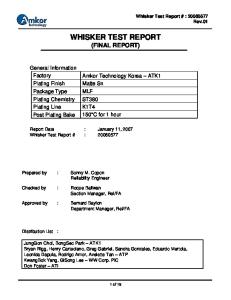
ELECTROMAGNETIC RADIATED FIELD DISTURBANCE
TEST
2. REFERENCE DOCUMENT
EN 55022 “Limits and methods of measurement of radio interference characteristics of information technology equipment”
TEST SETUP:
Acc. To Par. 9.1 of the ref. Std.
TEST LOCATION:
Semi-anechoic chamber (CISPR 16-1 :1993) Siemens+Matsushita type B84117-D6019-T232 Measure distance 3 meters
TEST EQUIPMENT USED FOR TEST:
EMI receiver Rohde & Schwarz Mod. ESMI Chase Antenna Mod. CBL 6111 A
TESTED PORT:
Enclosure
FREQUENCY RANGE:
30 - 1000 MHz
EMISSION LIMITS:
Tab. 4 of Reference Standard
UNCERTAINTY OF MEASURE:
Level of confidence = 95% Degree of freedom = 10 Coverage factor kp= 2,28 Combined uncertainty = 4,49 dB
TEST CONDITIONS:
MEASURED
Ambient temperature :
15 - 35 °C
24 3 °C
Ambient humidity :
25 - 75 %rH
40 5 %rH
Pressure :
85 - 106 kPa
(860 mbar - 1060 mbar)
Voltage :
950 50 mbar 12Vdc
5_10_EMCTR_16 REV.1 2014
OPERATING CONDITION (Rif. Section. 2) : #1
RESULT: WITHIN THE LIMIT
Pagina / Page 13 of 28
Rapporto di prova / Test report n.EMCTR_160016-0. Data / Date 11/04/2016
30MHz – 1GHz EN_55022_EMI_RAD_CLASS_A 65 60 EN 55022 F Quasi Peak Class A
Level in dBµV/m
55 50 45 40 35 30 25 30M
50
60
80
100M
200
300
400
500
800
1G
Frequency in Hz
Frequency (MHz)
QuasiPeak (dBµV/m)
Height (cm)
41.880000 64.000000 65.480000 66.800000 74.320000 77.840000 93.720000
47.8 42.2 46.3 48.7 45.2 46.1 48.7
174.0 194.0 257.0 288.0 258.0 333.0 257.0
Polarization
V V H V V V H
Azimuth (deg)
Margin (dB)
Limit (dBµV/m)
22.0 159.0 181.0 270.0 201.0 201.0 23.0
9.20 7.80 3.70 1.30 4.80 3.90 1.30
50.00 50.00 50.00 50.00 50.00 50.00 50.00
5_10_EMCTR_16 REV.1 2014
Final Result QuasiPeak
Pagina / Page 14 of 28
Rapporto di prova / Test report n.EMCTR_160016-0. Data / Date 11/04/2016
IMMUNITY TO RADIATED RF ELECTROMAGNETIC FIELD
TEST 3. REFERENCE DOCUMENT
EN 61000-4-3 Electromagnetic Compatibility (EMC) - Part 4 Testing and measuring techniques Section 3 : Radiated radio-frequency electromagnetic field - Immunity test
TEST SETUP:
Acc. to par. 7 of Basic standard
TEST LOCATION:
Semi-anechoic chamber (CISPR 16-1 :1993) Siemens+Matsushita type B84117-D6019-T232 Measure distance 3 meters
TEST EQUIPMENT USED FOR TEST:
RF generator
Signal
RF Amplifiers Directional Coupler Transmitting antenna
R&S mod. SME 03
5kHz - 3GHz
AR 250L 250W
150kHz - 220MHz
AR100W 100W AR-DC2500
220MHz 1000MHz
AR-DC6180
10 kHz – 220 MHz
FSA mod. S13014/1
80 – 1000 MHz
EMS-K1.04h
80MHz - 1GHz
-
Software
TESTED PORT:
Enclosure
FREQUANCY RANGE:
80 MHz - 1000MHz
SCAN DATA:
1s - 1% log.
IMMUNITY LEVEL:
3 V/m, 80% AM (1kHz)
PERFORMANCE CRITERION
A
MEASUREMENT UNCERTAINTY:
Level of confidence = 95%
Degree of freedom = 10
Coverage factor kp= 2,28
Combined uncertainty = 10,5 % MEASURED
Ambient temperature :
15 - 35 °C
24 3 °C
Ambient humidity :
25 - 75 %rH
40 5 %rH
Pressure :
85 - 106 kPa
(860 mbar - 1060 mbar)
Voltage :
950 50 mbar 12Vdc
OPERATING CONDITION (Rif. Section. 2) : #1;#2
RESULT: COMPLIANT Pagina / Page 15 of 28
5_10_EMCTR_16 REV.1 2014
TEST CONDITIONS:
Rapporto di prova / Test report n.EMCTR_160016-0. Data / Date 11/04/2016
TEST RESULTS AM, 80% 1kHz 3V/m POLAR.
COMPLIANT
A
ENCLOSURE front side
ENCLOSURE left side
ENCLOSURE right side
ENCLOSURE rear side
HORIZONTAL
NOT COMPLIANT B
C
COMPLIANT
A
NOT COMPLIANT B
NOTES
C
No performance degradation
No performance degradation
No performance degradation
No performance degradation
5_10_EMCTR_16 REV.1 2014
PORT
VERTICAL
Pagina / Page 16 of 28
Rapporto di prova / Test report n.EMCTR_160016-0. Data / Date 11/04/2016
TEST 4.
IMMUNITY TO ELECTROSTATIC DISCHARGE (ESD)
REFERENC E DOCUMEN T
EN 61000-4-2 Electromagnetic Compatibility (EMC) - Part 4 Testing and measuring techniques Section 2 - Electrostatic discharge immunity test.
TEST SETUP:
Acc. to par. 7 of Basic standard
TEST LOCATION:
Transitory phenomena area
TEST EQUIPMENT USED FOR TEST:
ESD generator Schaffner Mod. NSG 435-01 Discharge impedance 330 ohm / 150 pF
TESTED PORT:
Enclosure
IMMUNITY LEVEL:
4kV (direct and indirect contact) ; 8kV (direct air)
NUMBER OF DISCHARGES AND TIME BETWEEN SUCCESSIVE PULSES:
50 positive and 50 negative for each point of discharge (1 discharge / second)
PERFORMANCE CRITERION
B
MEASUREMENT UNCERTAINTY:
Level of confidence = 95% Degree of freedom = 10 Coverage factor kp= 2,28 Combined uncertainty of peak voltage level = 3,09 % Combined uncertainty of peak current level = 8,52 % Combined uncertainty of rise time = 5,45 % Combined uncertainty of curve decay points at 30 and 60 ns = 10,22 %
TEST CONDITIONS:
MEASURED
Ambient temperature :
15 - 35 °C
24 3 °C
Ambient humidity :
25 - 75 %rH
40 5 %rH
85 - 106 kPa
(860 mbar - 1060 mbar)
Voltage :
950 50 mbar 12Vdc 5_10_EMCTR_16 REV.1 2014
Pressure :
OPERATING CONDITION (Rif. Section. 2) : #1,#2
RESULT: COMPLIANT
Pagina / Page 17 of 28
Rapporto di prova / Test report n.EMCTR_160016-0. Data / Date 11/04/2016
TEST RESULTS DIRECT CONTACT DISCHARGE (FOR CONDUCTIVE SURFACES) Level : 4 kV For each voltage and polarity, apply 50 discharges. Enter the number of times the system responded according to a level A, B or C. TEST RESULTS
PERFORMANCE CRITERIA Pol. COMPLIANT
Discharge point 1
A + -
Antenna enclosure (external unit)
NOTES
NOT COMPLIANT
B
C
10 10
No performance degradation
DIRECT AIR DISCHARGE (FOR NOT CONDUCTIVE SURFACES) Level : 8 kV For each voltage and polarity, apply 10 discharges. Enter the number of times the system responded according to a level A, B or C. TEST RESULTS
PERFORMANCE CRITERIA Pol.
Discharge point
COMPLIANT A
NOTES
NOT COMPLIANT B
C
2
Enclosure internal unit
+ -
H H
No performance degradation
3
Enclosure control unit
+ -
H H
No performance degradation
5_10_EMCTR_16 REV.1 2014
NOTES : H = HIGH IMPEDENCE SURFACE, ESD CANNOT BE REPRODUCED.
Pagina / Page 18 of 28
Rapporto di prova / Test report n.EMCTR_160016-0. Data / Date 11/04/2016
INDIRECT DISCHARGE TO VCP (VERTICAL COUPLING PLANE) Level : 4kV For each voltage and polarity, apply 50 discharges. Enter the number of times the system responded according to a level A, B or C. TEST RESULTS
PERFORMANCE CRITERIA
COMPLIANT
Pol Discharge point
A
NOTES
NOT COMPLIANT B
C
4
Enclosure front side
+ -
10 10
No performance degradation
5
Enclosure left side
+ -
10 10
No performance degradation
6
Enclosure right side
+ -
10 10
No performance degradation
7
Enclosure back side
+ -
10 10
No performance degradation
INDIRECT DISCHARGE TO HCP (HORIZONTAL COUPLING PLANE) Level : 4kV For each voltage and polarity, apply 50 discharges. Enter the number of times the system responded according to a level A, B or C. PERFORMANCE CRITERIA
COMPLIANT
NOT COMPLIANT
Pol Discharge point 8
Horizontal coupling plane (external unit)
A + -
B 10 10
NOTES
C No performance degradation
5_10_EMCTR_16 REV.1 2014
TEST RESULTS
Pagina / Page 19 of 28
Rapporto di prova / Test report n.EMCTR_160016-0. Data / Date 11/04/2016
TEST 5. REFERENC E DOCUMEN T
IMMUNITY TO FAST TRANSIENTS / BURSTS
EN 61000-4-4 Electromagnetic Compatibility (EMC) - Part 4 Testing and measuring techniques Section 4 - Electrical fast transient burst immunity test.
TEST SETUP:
Acc. to par. 7 of Basic standard
TEST LOCATION:
Transitory phenomena area
TEST EQUIPMENT USED FOR TEST:
Burst Generator Hilo Test Mod. EFTG 4510 3-phase CDN Hilo Test Mod. CDN 414 Capacitive clamp Hilo Test Mod. EFTC-105
TESTED PORT:
AC Power Input Ports, DC Power Input Ports, signals/controls lines and Telecommunication Port
IMMUNITY LEVEL:
AC ports : 1 kV DC ports : 0,5 kV Signals/controls lines: 0.5 kV Telecommunication Port: 0.5 kV
PERFORMANCE CRITERION
B
MEASUREMENT UNCERTAINTY:
Level of confidence = 95% Degree of freedom = 10 Coverage factor kp= 2,28 Combined uncertainty of peak voltage level = 10,16 % Combined uncertainty of rise time = 20,08 % Combined uncertainty of frequency 5 kHz = 1,82 % Combined uncertainty of duration = 20,08 %
MEASURED
Ambient temperature :
15 - 35 °C
24 3 °C
Ambient humidity :
25 - 75 %rH
40 5 %rH
Pressure :
85 - 106 kPa
(860 mbar - 1060 mbar)
Voltage :
950 50 mbar 12Vdc
OPERATING CONDITION (Rif. Section. 2) : #1,#2
RESULT: COMPLIANT Pagina / Page 20 of 28
5_10_EMCTR_16 REV.1 2014
TEST CONDITIONS:
Rapporto di prova / Test report n.EMCTR_160016-0. Data / Date 11/04/2016
PORT n. 3 : DC Power Ports TEST
COUPLING MODE
TEST 1
(+) - Ref. ground
0,5KV
TEST 2
(-) - Ref. ground
0,5KV
TEST RESULT
IMMUNITY LEVEL
POL.
DISTURB. DURATION
REPETITION FREQ.
TEST DURATION
15 ms
5 kHz
60 s
15 ms
5 kHz
60 s
PERFORMANCE CRITERIA POL.
COMPLIANT
A
NOTES
NOT COMPLIANT
B
B
C
TEST 1
+ -
No performance degradation
TEST 2
+ -
No performance degradation
PORT n. 4 : (SIGNAL/CONTROL IN/OUT PORTS) COUPLING MODE
TEST 3
Capacitive Clamp
TEST RESULT
IMMUNITY LEVEL
0,5KV
DISTURB. DURATION
REPETITION FREQ.
TEST DURATION
15 ms
5 kHz
60 s
PERFORMANCE CRITERIA POL.
COMPLIANT
A TEST 3
POL.
+ -
B
NOTES
NOT COMPLIANT B
C No performance degradation 5_10_EMCTR_16 REV.1 2014
TEST
Pagina / Page 21 of 28
Rapporto di prova / Test report n.EMCTR_160016-0. Data / Date 11/04/2016
TEST
IMMUNITY TO SURGE
5. REFERENCE DOCUMENT
EN 61000-4-5 Electromagnetic Compatibility (EMC) - Part 4 Testing and measuring techniques Section 5 - Surge immunity test.
TEST SETUP:
Acc. to par. 7 of ref. Std.
TEST LOCATION:
Transitory phenomena area
TEST EQUIPMENT USED FOR TEST:
Surge Generator Hilo Test Mod. CWG 4-412 3-Phase CDN trifase Hilo Test Mod. CDN 414 Surge Generator HAEFELY Mod. PST Coupling Network HAEFELY mod. IP6.2 Decoupling Network HAEFELY mod.DEC1A
TESTED PORT:
AC Input Power Port, DC power Input Ports, signal control lines and Telecommunication Ports
IMMUNITY LEVEL:
AC: 1kV (differential mode) ; 2kV (common mode) DC: 0,5kV (common mode) Signals and Telecommunication : 1kV (common mode)
NUMBER OF SURGES: TIME INTERVAL BETWEEN SUCCESSIVE PULSES: PERFORMANCE CRITERION:
5 positive and 5 negative at the selected points 1
min.
B MEASUREMENT UNCERTAINTY:
Level of confidence = 95% Degree of freedom = 10 Coverage factor kp= 2,28 Combined uncertainty of peak voltage level = 9,36 % Combined uncertainty of rise time = 22,62 % Combined uncertainty of short-circuit current = 8,92 % Combined uncertainty of duration = 22,32 %
MEASURED
Ambient temperature :
15 - 35 °C
24 3 °C
Ambient humidity :
25 - 75 %rH
40 5 %rH
Pressure :
85 - 106 kPa
(860 mbar - 1060 mbar)
Voltage :
950 50 mbar 12Vdc
OPERATING CONDITION (Rif. Section. 2) : #1,#2
RESULT: COMPLIANT Pagina / Page 22 of 28
5_10_EMCTR_16 REV.1 2014
TEST CONDITIONS:
Rapporto di prova / Test report n.EMCTR_160016-0. Data / Date 11/04/2016
PORT n. 3 : DC POWER PORTS TEST
COUPLING MODE
TEST 4
(+) – (Reference plane) (COMMON MODE)
0.5 kV
10 + 9 F
1pul./min.
+/-
TEST 5
(-) – (Reference plane) (COMMON MODE)
0.5 kV
10 + 9 F
1pul./min.
+/-
TEST VOLTAGE
IMPEDENCE COUPLING
TEST FREQUENCY
Polarity
Performance Criteria RESULT
P COMPLIANT o l. A
B
NOT COMPIANT
NOTES
C
TEST 4
+ -
No performance degradation
TEST 5
+ -
No performance degradation
PORT n. 4 : SIGNAL / CONTROL LINES TEST
COUPLING MODE
TEST VOLTAGE
TEST 6
(Every single Line) – (Reference plane)
1 kV
IMPEDENCE COUPLING 40
TEST FREQUENCY
Polarity
1pul./min.
+/-
Performance Criteria P COMPLIANT o l. A TEST 6
+ -
B
NOT COMPIANT
NOTES
C No performance degradation
Pagina / Page 23 of 28
5_10_EMCTR_16 REV.1 2014
RESULT
Rapporto di prova / Test report n.EMCTR_160016-0. Data / Date 11/04/2016
IMMUNITY TO CONDUCTED RF-DISTURBANCES (COMMON MODE)
TEST
6. REFERENCE DOCUMENT
EN 61000-4-6 Electromagnetic Compatibility (EMC) - Part 4 Testing and measuring techniques Section 6 - Conducted disturbances induced by radio frequency fields immunity test .Electromagnetic compatibility.
TEST SETUP: TEST LOCATION: TEST EQUIPMENT USED FOR TEST:
Acc. to par.7 of Basic std. Semi-anechoic chamber
PORT TO TEST:
AC Power Input Ports, DC Power Input Ports, signals/controls lines and Telecommunication ports 150 kHz - 80 MHz 1s - 1% log. 3V (rms unmodulated), 80% AM, 1 kHz A
FREQUENCY RANGE: SCAN DATA: IMMUNITY LEVEL: PERFORMANCE CRITERION: MEASUREMENT UNCERTAINTY:
TEST CONDITIONS: Ambient temperature : Ambient humidity : Pressure :
RF signal Gen RF Amplif. Directional Coupler CDN CDN EM Clamp RF Attenuator
SME 03 AR 250L 250W AR-DC2500 M2/M3 ( 16 A ) T2 Mod. F-2031 6dB
Level of confidence = 95% Degree of freedom = 10 Coverage factor kp= 2,28 Combined uncertainty = 2,24 %
MEASURED 24 3 °C
15 - 35 °C
40 5 %rH
25 - 75 %rH 85 - 106 kPa
5kHz - 3GHz 0.01MHz 220MHz 10 kHz – 220 MHz 150kHz 230MHz 150kHz 230MHz 150kHz 230MHz 50 ohm 250 Watt
(860 mbar - 1060 mbar)
Voltage :
950 50 mbar 12Vdc
5_10_EMCTR_16 REV.1 2014
OPERATING CONDITION (Rif. Section. 2) : #1,#2
RESULT: COMPLIANT
Pagina / Page 24 of 28
Rapporto di prova / Test report n.EMCTR_160016-0. Data / Date 11/04/2016
TEST RESULTS AM 80% 1kHz 3V PERFORMANCE CRITERION PORT n.
COMPLIANT A
NOT COMPIANT B
NOTES
C
-----
No applicable: port not present
3 (DC Power Ports)
No performance degradation
No performance degradation
-----
No applicable: port not present
4 (Control / Signal ports)
5 (Telecommuni cation Port)
5_10_EMCTR_16 REV.1 2014
2 (AC Power Ports)
Pagina / Page 25 of 28
Rapporto di prova / Test report n.EMCTR_160016-0. Data / Date 11/04/2016
5 PHOTOGRAPHIC DOCUMENTATION
5_10_EMCTR_16 REV.1 2014
PHOTO 1 – EUT IDENTIFICATON
Pagina / Page 26 of 28
Rapporto di prova / Test report n.EMCTR_160016-0. Data / Date 11/04/2016
5_10_EMCTR_16 REV.1 2014
PHOTO N° 2 – RADIATED EMISSION SETUP
Pagina / Page 27 of 28
Rapporto di prova / Test report n.EMCTR_160016-0. Data / Date 11/04/2016
5_10_EMCTR_16 REV.1 2014
PHOTO N° 3 – RADIATED IMMUNITY SETUP
Pagina / Page 28 of 28