Toward Reliable Off Road Autonomous Vehicles Operating in Challenging Environments Alonzo Kelly, Omead Amidi, Mike Happold, Herman Herman, Tom Pilarski, Pete Rander, Anthony Stentz, Nick Vallidis, Randy Warner Robotics Institute
Carnegie Mellon University Pittsburgh, PA, USA
[email protected], etc.
Abstract. The DARPA PerceptOR program implements a rigorous evaluative test program which fosters the development of field relevant outdoor mobile robots. Autonomous ground vehicles are deployed on diverse test courses throughout the USA and quantitatively evaluated on such factors as autonomy level, waypoint acquisition, failure rate, speed, and communications bandwidth. Our efforts over the three year program have produced new approaches in planning, perception, localization, and control which have been driven by the quest for reliable operation in challenging environments. This paper focuses on some of the most unique aspects of the systems developed by the CMU PerceptOR team and the most immediate challenges that remain to be addressed.
1
Introduction
The potential applications of robotic ground vehicles have long been recognized. Off road mobile robots must operate effectively under forest canopy which occludes positioning satellite signals while the trees themselves present natural mazes to challenge motion planning. They must function in alpine areas where terrain slopes require safe operation in constant proximity to tipover, while precipitous ledges persistently threaten to end the mission in an instant. They must function in fields and forests where ground covering vegetation obscures both the shape of the ground and any occluded hazards. In short, off road autonomy is among the most ambitious of our aspirations for mobile robot technology. Much of the work to date has been motivated by military [2][8] and space [1], [10], applications although agriculture [5], mining [4], and forestry have received more recent attention. The system described in this paper has evolved from local [6] and global [9], planning systems that we developed for the Demo II program. Unlike most or perhaps all historical work on outdoor autonomous mobility, the PerceptOR program emphasizes independently administered evaluative testing as the primary mechanism to drive progress. The overall goal has been to simultaneously maximize autonomy, reliability, and speed.
2 A.Kelly, O. Amidi, M. Happold, H. Herman, T. Pilarski, P. Rander, A. Stentz, N. Vallidis, R. Warner
Tests are conducted on an unrehearsed basis, meaning the development team has no detailed knowledge of specific terrain before the test. While the development team may see the test courses during the conduct of the tests, individuals who operate the system are prevented from seeing the test courses until all tests are complete. The overall intent is to simulate the conditions of actual deployment of UGVs. This paper outlines the final design of the system produced by the CMU PerceptOR team, results achieved, and some of the most immediate challenges that remain to be addressed
2
System Design
Fig 1: Autonomous Ground and Air Vehicles. A Honda ATV and Yamaha Rmax Helicopter were retrofitted for autonomy.
The UGV hardware design is based on the Honda Rubicon All Terrain Vehicle (ATV). Elements for man-aboard driving were removed entirely and replaced with an autonomy retrofit. SICK ladars were custom modified to scan in a second axis to convert them to 2D imaging devices. Up to four of these devices have been used per vehicle at various times to generate forward and rearward perception for obstacle avoidance and omnidirectional views for operator interface purposes. Two stereo pairs developed by Sarnoff Corporation provide passive forward range imaging. Several monochrome teleop cameras are provided. Monocular digital color and analog FLIR cameras are used for estimating terrain composition. A Smiths land inertial navigation system and GPS receiver provide global position estimates. Over a three year period, the objectives and our experiences in field tests have driven us to implement new approaches at all levels of the traditional autonomy software hierarchy – from gross motion planning to reactive low level control. Some of the new elements are discussed below.
Toward Reliable Off Road Autonomous Vehicles
3
3
Position Estimation and Mapping
Various disappointments in field experiments have driven us to redesign the position estimation and mapping approach in order to respond to the challenges of generating high fidelity perception on a moving platform. While some of the following techniques have been used in earlier work, we take them to new extremes and organize the principles in this work. 3.1 Accumulation – Distortion Tradeoff Nonideal pose estimates cause distortions in environmental models that are created with them. Pose error accumulation rate often increases with motion, motion is more difficult to measure on rough terrain, and sensitivity to these errors increases as the desired fidelity of perception increases. There may at times be a fundamental requirement to accumulate data in a region; for example, in order to compute a region property the size of a wheel or of a vehicle. Nevertheless, the value of excess data accumulation (beyond the fundamental requirements) is at odds with the cost of the cumulative effects of pose error. Ironically, despite good intentions, too much oversampling eventually incorporates enough distortion to make it impractical to reliably resolve the features of interest at the scale of interest. Several design principles have emerged to manage this tradeoff. The impact of distortion can be minimized by … • Minimum Accumulation … accumulating no more data than necessary. Hence, when obstacle signatures can be computed from one scan line of ladar data they should be. When a few lines are necessary, then only a few lines should be used. • Exploit Signal Properties … exploiting the best properties of pose estimate. It is better to compute region properties within ladar scan lines than across them. If two sets of consecutive lines must be accumulated, then the computation is organized to compute high fidelity local results in each set first, and then merge them in a manner consistent with the larger error accumulated between the sets. • Engineer the Distortion Signal. … providing the best possible pose signal(s). Ladar(s) can be oriented to extract preferred information from the faster of the two rotation axes. Multiple custom-designed pose estimates can easily be generated for multiple purposes. These principles drive our approach to position estimation and mapping. A hierarchical arrangement of data structures provides decreasing periods of data accumulation and increasing levels of detail as the hierarchy is descended. An associated hierarchy of position estimates trade absolute accuracy for relative as the hierarchy is descended. Data is accumulated with one pose estimate but localized with the next highest estimate and, if necessary, re-localized to track the growing mis-registration between the two.
4 A.Kelly, O. Amidi, M. Happold, H. Herman, T. Pilarski, P. Rander, A. Stentz, N. Vallidis, R. Warner
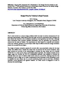
3.2 Multiple Pose Estimates and Maps At the global level, a global pose estimate is computed from all available sensing several times a second. This estimate is used to control motion with respect to globally specified waypoints, and to fuse onboard and externally provided geo-referenced data. At the local level, a local pose estimate is computed based only on sensing which does not project onto position states. It does not process GPS readings, nor would it process terrain aids like absolute landmarks if they were available. This estimate drifts with respect to the global estimate but it is completely immune to the characteristic jumps in GPS position which occur before loss of lock on satellite(s) and at their reacquisition. This estimate is used to provide feedback to motion control and to estimate motion relative to obstacles for obstacle avoidance purposes. Neither of these uses requires an absolute sense of position on the earth.
Fig 2: Dual Maps and Position Estimates. Overhead renderings of the local map (top) and corresponding global map (bottom) are shown at four closely spaced periods of time. Over this time, the global estimate moves the vehicle to the right by one vehicle width due to GPS drift. In the global map, the dark roadway is georegistered and does not move. The obstacles, however, were located by perception and placed in the local map so they shift right with the vehicle. In this way, obstacle avoidance becomes immune to GPS jumps.
At the perceptual level, we have not yet invested in a different estimate. However, the assessment of local shape does not require a sense of absolute attitude or heading and errors in these quantities need not be passed to shape-level processing. An estimate based only on integrating gyros might be valuable. Fig 2 illustrates the operation of the two highest levels of mapping during a GPS jump. The local map is re-registered to the global map at high rates so that while the relative position (local-level shape) of perception-derived data remains stable, its global position is adjusted continuously.
Toward Reliable Off Road Autonomous Vehicles
4
5
Perception
In addition to the aspects of perception which are implied above, a few other design approaches have emerged in order to address the challenges of vegetated and forested terrain. 4.1 3D Volumetric Density Mapping While, in many earlier works, systems have been able to function using an overhead planar projection of the robot and the environment, and while we continue to do so at the global level, the overhead projection of the local map is derived from a more detailed 3D representation (Fig 3). Like the planar local map, this data structure is implemented as a circular queue which wraps around in 3 dimensions in order to avoid the need to move the data in memory as the vehicle moves over distances much larger than the size of the map. Both the 2D and 3D local maps have coordinates aligned with and orthogonal to gravity to facilitate attitude predictions. In this data structure, the entire volume swept by the vehicle during candidate
Fig 3: 3D Perception. Left: The colorized point cloud to the left indicates the typical 3D structure of a forested scene on a trail. Red regions are nontraversable; blue ones are traversable. Right: Density scores in a vertical column through the point cloud.
motions can be tested for collisions. While the height of the column of data intersected by the vehicle does not vary, its vertical position in the 3D map does vary. Nonetheless, given the vertical position of the column, it is possible to identify the relevant data and collapse its net assessment into a 2D cell in the planar representation. The basic attribute extracted in each cell is the “density” computed as the ratio of the number of hits to hits plus misses. A cell gets a hit if the ladar beam
6 A.Kelly, O. Amidi, M. Happold, H. Herman, T. Pilarski, P. Rander, A. Stentz, N. Vallidis, R. Warner
terminates inside it and a miss if it was passed through. This calculation requires that each cell in the line from the sensor to the returning cell be identified in a ray tracing process. 4.2 Learning to Estimate the Ground Plane Of course, the problem of identifying the ground plane, or more precisely the shape of the load bearing surface, is not straightforward in environments with vegetative ground cover. In meadows and under forest canopy, we have found it necessary to estimate the supporting surface based on the density scores.
Fig 4: Computing the Load Bearing Surface Under Ground Cover. The yellow line in the inset image represents the slice through the world model density scores which is being processed. The neural net lowers the grass and raises the tree which is the correct adjustment of the load bearing surface.
Based on the learning principle originally developed for agricultural robots in [11] we developed a neural network which learned how to adjust a preliminary estimate of the load bearing surface elevation based on observing the ground truth data generated when the vehicle drives over terrain in the learning phase. Fig 4 shows the operation of the neural net in a typical scene.
5
Motion Planning
In order to manage computational complexity, the planning system is also arranged hierarchically. It is composed of the Dstar global planner [9] and the Ranger local planner [6]. These elements were integrated for the first time on
Toward Reliable Off Road Autonomous Vehicles
7
PerceptOR. The basic principle used is the assumption that high fidelity models of vehicle dynamics and maneuverability are less important farther from the vehicle than near it (Fig 5.)
Start Goal
Fig 5: Hierarchical Motion Planner. Candidate trajectories are produced by forward simulation of the vehicle dynamics out to some distance after which the optimal remaining path in an 8-conneced grid with expanded obstacles is used. An elevation grid is used in the high fidelity portion of the motion simulation and the total line integral over a cost field of both portions of each optimal path is used to select the option to execute.
Paths between waypoints of hundreds of meters separation are generated autonomously. Routinely, the system comes to a stop while following the best available plan because there are apparently no safe options for proceeding. A set of behaviors are then used to verify the assumption of no safe forward path and implement various recovery mechanisms. First, a slow speed perception scan to regenerate the area in view is performed while the vehicle is stationary. If this mechanism does not generate a way forward, the system next executes a very effective reactive backup maneuver attempting to align the vehicle with the direction preferred by global planning. Dense surrounding obstacles will rarely cause this step to fail. A nonholonomic motion planner was developed to address these cases. If it fails, the system asks the operator for help.
Fig 6: Nonholonomic Motion Planner. Left: In this zero heading slice (restricted to forward motions for display), steering functions to a regular array of neighboring poses are encoded. Right: A custom 5 point turn is generated to turn after detecting a natural cul-de-sac
8 A.Kelly, O. Amidi, M. Happold, H. Herman, T. Pilarski, P. Rander, A. Stentz, N. Vallidis, R. Warner
This planner is based on a generalization of a grid which we call a pose lattice. The space of robot poses (x,y,heading) is discretized into a dense 3D grid and the trajectory generator described in [7] is used to connect every node to every reachable neighboring node out to some practical radius. The pose lattice structure can then be interpreted as a graph for purposes of implementing heuristic search (A* is implemented at the moment). The structure itself can be represented implicitly in terms of a repeated template. The result is a regular sampling of state space which encodes, to finite resolution, all possible motions between neighboring states using only feasible motions. Complex motions respecting the constraints of local obstacles are then generated by optimal network search.
6 Project Results Test results on the PerceptOR program are tallied at the system level in order to focus effort on overall performance. Among the data collected is the number of times field safety personnel intervened in order to prevent vehicle damage, the communications bandwidth used, system ability to reach desired waypoints, speed, distance, and time. The number of operators was reduced to one near the middle of the program and at times, tests have been performed to evaluate the viability of restricting operator intervention to those cases when the robot asks for help. Test courses were chosen by DARPA at each of four army bases in the north east, south central, south west and north west of the United States. Systems were thereby exposed to forested, desert, and mountainous terrains under varying weather conditions in different seasons. Exercises, consisting of several partially repetitive runs per day, were normally conducted over a one week period at each site. Two sites were visited twice in order to assess improvement over time. Approximate cumulative data for all six exercises are summarized below in Table 1 A rough sense of improvement over time can be obtained by comparing the cumulative scores for all 6 exercises with those of the final one. One of the tests of the fifth exercise is illustrated in detail in Fig 7. Item Number of Runs Distance Traveled Test Duration Average Speed Uplink Distance Density Downlink Distance Density
Unit m s m/s Kb/m Kb/m
Cumulative 183 81,094 230,606 0.35 34.5 705
Last Test 36 29,376 49,172 0.60 4.8 327
Table 1: Cumulative and Final Data for PerceptOR Program Exercises (CMU Team Only)
Toward Reliable Off Road Autonomous Vehicles
9
Fig 7: Test Run with Forest, Meadow, and Trail. After driving perhaps 50 meters through a forest, the system collides harmlessly with a small tree. The remote operator takes control to clear the error and move the vehicle away from the hazard. The system acquires a trail and follows it autonomously for a long distance before determining that the trail is no longer heading toward the goal. It then executes a multi point turn maneuver, retraces its path, and exists the trail at an appropriate place. The operator reconfigures the software to tolerate tall grass (assessor change) near the end of the run and it terminates at a fallen log visible as the bright streak in the lower left cost image.
7 Conclusions and Outlook The PerceptOR program has been unprecedented in its rigorous approach to evaluative testing of unmanned ground vehicles. System performance has clearly improved over time in response to test results, and many opportunities for more performance improvements obviously remain. Among those improvements are immediate issues in perception and planning. We remain dissatisfied with the level of adaptability of perception algorithms to varying terrain. Less manual tuning of algorithms could potentially be achieved by creating a higher level understanding of overall context (forest, trail) in the system. Issues relating to the interplay between perception and planning are becoming more significant. The advantages of real time replanning come at the cost of a
10 A.Kelly, O. Amidi, M. Happold, H. Herman, T. Pilarski, P. Rander, A. Stentz, N. Vallidis, R. Warner
system which can change the global plan too radically and too often. A lack of aggregate understanding of the local situation can lead to futile struggles to forge a way through a stand of trees immediately beside a perfectly good trail. Some of the grand challenges of outdoor autonomy are well understood. A few are detecting small obstacles at high speeds, detecting negative ones at any speed, passive operations and night, and perceiving the groundplane and hazards hidden beneath obscuring vegetation. In addition to some progress on some of these fronts, the main contribution of the PerceptOR program has been the most rigorous attempt to date to quantify the present state of the art.
8 References [1] G. Andrade, F. Amara, P. Bidaud and R. Chatila, “Modelling of Robot-Soil Interaction for Planetary Rover Motion Control”, Proc. IEEE/RSJ ICIRS, Victoria, Canada, 1998. [2] S Balarski and A. Lacaze, “World Modelling and Behavior Generation for Autonomous Robot Ground Vehicle”, Proc IEEE ICRA, San Francisco, USA, April 2000. [3] P. Belluta, R. Manduchi, L. Matthies, K. Owens, and A. Rankin, “Terrain Perception for Demo III”. Proceedings of IEEE Intelligent Vehicles Symposium, pages 326-331, October 2000. [4] J. Roberts, P. Corke, and G. Winstanley, “Development of a 3,500 tonne field robot”, The International Journal of Robotics Research, 18(7):739-752, July 1999 [5] H. Hagras, M. Colley, V. Callaghan, and M. Carr-West, “Online Learning and Adaptation of Autonomous Mobile Robots for Sustainable Agriculture”, Auton. Robots 13(1): 37-52 (2002). [6] A. Kelly, and A. Stentz, “Rough Terrain Autonomous Mobility – Part 2: An Active Vision, Predictive Control Approach”, Autonomous Robots, 5, 163-198, 1998. [7] A. Kelly, and B. Nagy, “Reactive Nonholonomic Trajectory Generation via Parametric Optimal Control”, International Journal of Robotics Research, July 2003. [8] A. Lacaze, Karl Murphy, M. Delgiorno, “Autonomous Mobility for the Demo III Experimental Unmanned Vehicles”, AUVSI 2002. [9] A. Stentz, “Optimal and Efficient Path Planning For Partially-Known Environments”, Proc IEEE ICRA, May 1994. [10] P. Schenker, T. Hunstberger, P. Pirjanian, S. Dubowski, K. Iagnemma, and V. Sujan, “Rovers for Agile Intelligent Traverse of Challenging Terrain Proceedings of the 7th International Symposium on Artificial Intelligence, Robotics and Automation in Space, i-SAIRAS, Nara, Japan, May 2003. [11] C. Wellington and A. Stentz, “Learning Predictions of the Load-Bearing Surface for Autonomous Rough-Terrain Navigation in Vegetation.” International Conference on Field and Service Robots, July 2003, pp 49-54.