OXFW971 Data Sheet
Multi-Channel Isochronous Streaming FireWire Audio Controller
Features
Benefits
DS-0017 Nov 06
16 configurable audio channels at sample rates up to 192 kHz
S/PDIF & MIDI interfaces for both input & output
Audio sample rates of 32 kHz, 44.1 kHz, 48 kHz, 88.2 kHz, 96 kHz & 192 kHz, with 16-, 24-, & 32-bit samples
Supports AM824 audio format as specified in IEC 61883-6
Master clock to synchronize with external DAC
Supports IEEE 1394a & IEEE 1394b at speeds up to S800
Pin-compatible with the OXFW970
Rotary encoder input & pulse-width modulation outputs generate analog mixer levels
Debug capabilities using internal UART or JTAG ports
3.3-V I/O, 1.8-V core operating voltage
100-pin TQFP (14 × 14 × 1 mm)
Supports Mac OS® & Windows®
Windows driver SDK—ASIO 2.0, low latency audio & WDM audio streams, direct monitoring & device aggregation
High integration of flash, PLLs & RAM ensures low BOM cost
Integrated DSP function provides MIPS for applications such as sound equalization
Optimized firmware fits into 1-Mbit internal flash
Multiple clock domains provided for flexible clock source locking
32-bit fixed point to floating point conversion enabled for non-AM824 streaming applications
Remote flash programming utilities provided for ease of support
Low-jitter audio master clock for clock recovery (128,192,256,384 or 512 fs)
User-friendly firmware SDK
Complete firmware source & documentation
AV/C stack & 1394 API
DSP library (e.g., for mixing equalization)
Supports vendor-unique command extensions
External—Free Release
1
Multi-Channel Isochronous Streaming FireWire Audio Controller
Overview
Oxford Semiconductor, Inc.
The Oxford Semiconductor OXFW971 is a highly-integrated audio streaming controller for FireWire® isochronous applications. The OXFW971 builds on the achievements of the OXFW970, but offers a range of additional features:
Up to 16 I/O channels with multiple configuration options, including:
Simultaneous 8 input & 8 output (up to 96 kHz sample rate)
S/PDIF input & S/PDIF output (up to 96 kHz sample rate)
MIDI input & MIDI output
High peripheral integration, resulting in lower operational production costs
Improved processor performance, to support an equalization function for certain applications
The OXFW971 provides a bidirectional FireWire S400/S800 link between a PC or Mac® and a range of audio interfaces. The combination of eight audio channels (both input & output) with support for both S/PDIF and musical instrument digital interface (MIDI) make the OXFW971 a highly-integrated solution for GarageBand™ I/O boxes, external sound card and speaker applications. With an ARM7TDMI® embedded processor, 1 Mbits of flash memory and a range of peripherals integrated on-chip, the device provides a low-cost solution for a variety of applications.
Device Functionality
The OXFW971 has a sophisticated clocking scheme, which allows it to be used in a variety of system configurations. It supports an external word clock input and can generate a low-jitter audio master clock (128, 192, 256, 384 or 512 fs) for external DACs, with optional clock smoothing. The high-speed UART allows applications with a second microcontroller to be controlled through the FireWire link. This facility allows users to interface with their preferred microprocessors, utilizing a transparent channel over a 1394 link. Such a feature can be useful where it is necessary to re-use existing firmware or support more specific customer applications. Other devices, such as DACs, can be controlled by the lowspeed serial interfaces, which are compatible with two-wire serial and SPI interfaces.
2
External—Free Release
DS-0017 Nov 06
Oxford Semiconductor, Inc.
Applications
Multi-Channel Isochronous Streaming FireWire Audio Controller
The OXFW971 connects seamlessly to a range of audio processor chips for applications that require AC-3/DTS decoding, Dolby® Virtual audio processing or Virtual Pro Logic II surround sound, including the following:
Prosumer breakout boxes
External surround sound cards for laptops—for DVD playback, games & music
Sound card solutions requiring multiple I/O S/PDIF output
Musical I/O interfaces with 8-in/8-out channels; MIDI in/out, S/PDIF in/out
Speaker solutions with streamed 7.1/5.1/2.1/2.0 output
Bus-powered 2.0/2.1 FireWire speakers
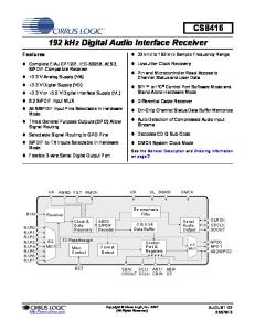
Figure 1 shows how the OXFW971 might be used in a prosumer breakout box; in this example, using 8 in/out, S/PDIF in/out and MIDI in/ out. Figure 1 OXFW971 Used in a Prosumer Breakout Box Buttons/Dials 12-V Main Block
Power Management LEDs
PC/Mac
S/PDIF In
S/PDIF Out
FireWire
1394 A/B PHY Optical/ Coaxial Interface
I8S OXFW971
ADC ADC ADC ADC
Buffers
Optical/ Coaxial Interface
Line In/Mic 8 Channel
Midi In/Out
Audio I8S
Audio DAC
8 Channels
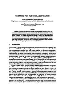
Figure 2 on page 4 shows an example sound card application using the OXFW971.
DS-0017 Nov 06
External—Free Release
3
Multi-Channel Isochronous Streaming FireWire Audio Controller
Oxford Semiconductor, Inc.
Figure 2 OXFW971 Sound Card Sample Application 12-V Main Block
Power Management
LEDs Buttons/Dials
Audio Decoder
PC/Mac
1394 A/B PHY
S/PDIF In
Optical/ Coaxial interface
S/PDIF Out
Optical/ Coaxial interface
S/PDIF 6-Channel Serial
ADC
OXFW971
Line In/Mic
Buffers MIDI In/Out
8-Channel Audio
Control
Audio DAC Optional device
Development Support
4
The OXFW971 is shipped with a full software development kit (SDK), which includes full documentation and firmware containing example applications for musical I/O devices such as multi-channel analogue output with 8-channel, S/PDIF, MIDI input and output to PC/Mac via FireWire; and external sound card devices such as 3D audio games, DVD audio decoding, home cinema audio decoding and FireWire streaming 5.1/7.1 speakers. PC drivers are also available for these applications.
External—Free Release
DS-0017 Nov 06
Oxford Semiconductor, Inc.
Multi-Channel Isochronous Streaming FireWire Audio Controller
Environmental Characteristics
Tables 1 to 3 detail the required operating conditions for the device and the DC electrical characteristics.
Table 1 Absolute Maximum Device Ratings Symbol
Parameter
Rating
Units
VDD
DC supply voltage
1.8 V 3.3 V
2.7 3.8
V
VIN
DC input voltage
3.3-V input buffer 3.3-V interface/5-V tolerant input buffer
3.8 6.5
V
VOUT
DC output voltage
3.3-V output buffer 3.3-V interface/5-V tolerant output buffer
3.8 6.5
V
TSTG
Storage temperature
Storage temperature
–40 to 85
°C
Table 2 Recommended Operating Conditions Symbol
Parameter
Rating
Units
VDD
DC supply voltage for internal DC supply voltage for I/O block
1.8 V 3.3 V
1.8 ± 0.15 3.3 ± 0.3
V
VIN
DC input voltage
3.3-V input buffer 3.3-V interface/5-V tolerant input buffer
3.3 ± 0.3 3.0~5.25
V
VOUT
DC output voltage
3.3-V output buffer 3.3-V interface/5-V tolerant output buffer
3.3 ± 0.3 3.3 ± 0.3
TA
Operating temperature range
0 to 85
°C
Table 3 Device I/O Buffer Electrical Characteristics (Sheet 1 of 2) Symbol
Parameter
Condition
Min 2.0
VIH
Input high voltage
CMOS Interface
VIL
Input low voltage
CMOS Interface
VT
Switching threshold
VT +
Schmitt trigger, positive-going threshold
CMOS
VT -
Schmitt trigger, negative-going threshold
CMOS
IIH
Input high current: Input buffer Input buffer with pull-down
VIN = VDD
Input low current: Input buffer Input buffer with pull-up
VIN = VSS
VOH
Output high voltage
IOH = –1 µA IOH = –1 mA to –24 mA
VOL
Output low voltage
IOL = 1 µA IOL = 1 mA to 24 mA
IOZ
Tri-state output leakage current
VOUT = VSS or VDD
IDD
Quiescent supply current
IIL
DS-0017 Nov 06
Type
Max
V 0.8 1.4
External—Free Release
0.8
–10 –60
V V
33
10 60
–33
10 –10
VDD – 0.05 2.4
-10
V V
2.0
–10 10
Units
µA
µA
V 0.05 0.4
V
10
µA
100
µA
5
Multi-Channel Isochronous Streaming FireWire Audio Controller
Oxford Semiconductor, Inc.
Table 3 Device I/O Buffer Electrical Characteristics (Sheet 2 of 2) Symbol
Parameter
Condition
Min
Type
Max
Units
CIN
Input capacitance
Any input & bidirectional buffers
4
pF
COUT
Output capacitance
Any output buffer
4
pF
Pinout & Package Information
The device is supplied as a 100-pin TQFP package (14 × 14 × 1 mm). Figure 3 shows the chip layout.
Figure 3 OXFW971 Pinout
AUDIO1_TX_D3
AUDIO1_TX_D2
AUDIO1_RX_D2
AUDIO1_RX_D1
AUDIO1_RX_D0
AUDIO1_TX_D1
VSS3V3
VDD3V3
AUDIO_NFS_CLK_IN
TEST_MODE1
AUDIO1_NFS_CLK_OUT
VSS1V8
VDD1V8
VBB_PLL
PLL2073_AVSS
PLL2073_DVDD
PLL2073_AVDD
PLL2073_DVSS
UART2_SOUT
UART2_SIN
VSS3V3
VDD3V3
SEL_B_PHY
JTAG_TDO
TEST_MODE0
FLASH_EXHV
76
1
UART3_SOUT
FLASH_VCC3F JTAG_TDI
VSS3V3
JTAG_TCLK
VDD3V3
JTAG_TMS
AUDIO1_RX_WORD_CLK
I2C_SCL
AUDIO2_RX_WORD_CLK
TEST_MODE2
AUDIO1_TX_WORD_CLK
FLASH_VSSF
AUDIO2_TX_WORD_CLK
FLASH_VSSL
VCO_FS_PDOUT
FLASH_VCCL
SYS_FS_PDOUT
I2C_SDA
VSS1V8
IR_RX
VDD1V8
PWM0
AUDIO2_RX_D3
JTAG_UART_SEL
AUDIO2_RX_D2
OXFW971
VDD1V8 VSS1V8
AUDIO2_RX_D1 AUDIO2_RX_D0
PWM3
AUDIO2_TX_D3
PWM2
AUDIO2_TX_D2
PWM1
VSS3V3
AUDIO1_NFS_CLK_OUT
AUDIO2_TX_D1
VDD3V3
AUDIO2_TX_D0
VSS3V3
AUDIO2_RX_BIT_CLK
Z_FORCE_FLASH Z_RESET
AUDIO2_TX_BIT_CLK 51
26
AUDIO1_RX_BIT_CLK
VDD3V3
AUDIO1_TX_BIT_CLK
AUDIO1_TX_D0
VSS3V3
VDD3V3
LINK_LPS
LINK_PINT
LINK_LINK_ON
LINK_LREQ
External—Free Release
LINK_PCLK
LINK_LCLK
VSS1V8
VDD1V8
LINK_CTL0
LINK_CTL1
LINK_PD0
LINK_PD1
LINK_PD2
LINK_PD3
VSS3V3
VDD3V3
LINK_PD4
LINK_PD5
LINK_PD6
LINK_PD7
6
AUDIO1_RX_D3 UART3_SIN
FLASH_VCCF
DS-0017 Nov 06
Oxford Semiconductor, Inc.
Multi-Channel Isochronous Streaming FireWire Audio Controller
Table 4 OXFW971 Pin Allocations (Sheet 1 of 2) Pin
No. Bits
Name
Type(1)
Description
LINK (External I/F) (16 pins) 26, 27, 28, 29, 32, 33, 34, 35
8
BD_4T
PD[7:0]
PHY-Link data bus
36, 37
2
BD_4T
CTL[1:0]
PHY-Link control bus
41
1
IU
PCLK
49.152 / 98.304 MHz clock sourced by PHY. Drives the OXFW971 main clock system
42
1
O_4
LREQ
Link request
43
1
IU
LINKON
Requests Link to power up when in low power mode
45
1
O_4
LPS
Indicates to PHY that link is powered & ready
40
1
O_8
LCLK
B mode only—PCLK returned to PHY
44
1
IU
PINT
B mode only—PHY Interrupt
85
1
5_BU_6T
AUDIO1_NFS_CLK_OUT(2)
Sys clock generated nFs clock (to DAC)
21
1
5_BU_6T
PWM/ AUDIO2_NFS_CLK_OUT(2)
Sys clock generated nFs clock (to DAC)
84
1
5_IU
AUDIO_NFS_CLK_IN
Returned (smoothed) nFs clock (from VCO)
65
1
5_B_4T
SYS_FS_PDOUT
Output of audio phase detector (from sys clk)
66
1
5_B_4T
VCO_FS_PDOUT
Output of audio phase detector (from VCO clk)
49
1
5_BU_4T
AUDIO1_TX_BIT_CLK(3)
First audio core I2S bit clock (at data bit frequency)
68
1
5_BU_4T
AUDIO1_TX_WORD_CLK
First audio core I2S word Clock (at Fs frequency)
76, 77
2
O_4
AUDIO1_TX_D[3:2]
First audio core audio transmit data (bits [3:2])
81, 48
2
5_BU_4T
AUDIO1_TX_D[1:0]
First audio core audio transmit data (bits [1:0])
51
1
5_BU_4T
AUDIO1_RX_BIT_CLK(3)
First audio core I2S bit clock (at data bit frequency)
70
1
5_BU_4T
AUDIO1_RX_WORD_CLK
First audio core I2S word Clock (at Fs frequency)
75, 78, 79, 80
4
5_BU_4T
AUDIO1_RX_D[3:0]
First audio core audio receive data
52
1
5_BU_4T
AUDIO2_TX_BIT_CLK(3)
Second audio core I2S bit clock (at data bit frequency)
67
1
5_BU_4T
AUDIO2_TX_WORD_CLK
Second audio core I2S word clock (at Fs frequency)
58, 57, 55, 54
4
O_4
AUDIO2_TX_D[3:0]
Second audio core audio transmit data
53
1
5_BU_4T
AUDIO2_RX_BIT_CLK(3)
Second audio core I2S bit clock (at data bit frequency)
69
1
5_BU_4T
AUDIO2_RX_WORD_CLK
Second audio core I2S word clock (at Fs frequency)
62, 61, 60, 59
4
5_BU_4T
AUDIO2_RX_D[3:0]
Second audio core audio receive data
91
1
P
PLL_DVDD
PLL digital 1.8V
93
1
P
PLL_DVSS
PLL digital GND
92
1
P
PLL_AVDD
PLL analogue 1.8V
90
1
P
PLL_AVSS
PLL analogue GND
89
1
P
VBB_PLL
PLL bulk bias
PDET (5 pins)
AUDIO1 (12 pins)
AUDIO2 (12 pins)
PLL (5 pins)
DS-0017 Nov 06
External—Free Release
7
Multi-Channel Isochronous Streaming FireWire Audio Controller
Oxford Semiconductor, Inc.
Table 4 OXFW971 Pin Allocations (Sheet 2 of 2) Pin
No. Bits
Name
Type(1)
Description
UART1 / JTAG (5 pins) 15
1
5_ID
JTAG_UART_SEL
Input only. Selects between JTAG & UART mode: 0—UART 1—JTAG
100
1
O_4
JTAG_TDO
Or debug UART1 transmitter serial data output
4
1
5_BU_4T
JTAG_TDI
Or debug UART1 active-low Request-to-Send output
5
1
5_IU
JTAG_TCLK
Or debug UART1 receiver serial data input
6
1
5_IU
JTAG_TMS
Or debug UART1 active-low clear-to-send input
95
1
5_BU_4T
UART2_SIN
Second UART serial input
94
1
5_BU_4T
UART2_SOUT
Second UART serial output
74
1
5_BU_4T
UART3_SIN
Third UART serial input
73
1
5_BU_4T
UART3_SOUT
Third UART serial output
7
1
5_BU_6T
I2C_SCL
I2C master serial clock
12
1
5_BU_6T
I2C_SDA
I2C master serial data
1
5_BU_4T
IR_RX
IR_RX input
3
5_BU_4T
PWM[3:0]
Pulse width modulated output bits [3:0]
24
1
5_IU_S
FORCE_FLASH
Allows FLASH memory programming (Schmitt)
8, 86, 99
3
5_ID_S
TEST_MODE
Selects various test modes (Schmitt)
25
1
5_I_S
Z_RESET
Main asynchronous reset. JTAG reset to ARM (Schmitt)
98
1
5_ID_S
SEL_B_PHY
Selects between A or B 1394 mode (schmitt): 0—A 1—B
1
1
P
FLASH_EXHV
HV input or monitoring input (test mode) Leave unconnected in normal mode
2
1
P
FLASH_VCCF
Power to FLASH core (1.8 V)
9
1
P
FLASH_VSSF
GND to FLASH core
3
1
P
FLASH_VCC3F
Power for(due to 3.3-V I/O)
11
1
P
FLASH_VCCL
Power for core test mux logic I/O & internal (1.8 V)
10
1
P
FLASH_VSSL
GND for core test mux logic I/O & internal
UART2 (2 pins)
UART3 (2 pins)
I2C (2 pins)
IR_RX (1 pin) 13 PWM (4 pins) 18, 19, 20, 14 Miscellaneous
Flash Memory
8
External—Free Release
DS-0017 Nov 06
Oxford Semiconductor, Inc.
Multi-Channel Isochronous Streaming FireWire Audio Controller 1
Note to Table 4:
W—Tolerance 5
Type key: either P (power) or format is [(W_)X(Y)(_Z(A))] where the following conventions apply:
X—Type
Y—Pull
Z—Drive
5V
I
Input
U
Pull up
4
4 mA
3V3
O
Output
D
Pull down
8
8 mA
B
Bidirectional
None
12
12 mA
2
3
A—Other T
Tristate Normal
S
Schmitt
The Audio1 and Audio2 NFS clock output pins are not necessarily associated with the Audio1 and Audio2 cores; they are selectable. Before committing to an application design, check which clock is associated with which core. See the Clocks chapter in the OXFW971 Hardware Reference Manual for details. The function of the Audio1 and Audio2 bit clocks differs according to whether the OXFW971 is used in slave or master mode. For details, see the Clocks chapter in the OXFW971 Hardware Reference Manual.
As shown in Table 5, any of the 32 GPIO pins can be assigned to a primary function, an alternative function or as general-purpose I/O in response to the peripheral control register settings. See the OXFW971 Hardware Reference Manual for further details. Table 5 Assignment of Primary, Alternative & GPIO Functions to Pins (Sheet 1 of 2) Bit No.
Pin No.
Primary Function
Alternative Function
GPIO Function
0
14
PWM0 (output)
SPI_SS_N (I/O)
GPIO0(4)
1
20
PWM1 (output)
I2C_GSI_SL (output)
GPIO1(4)
2
19
PWM2 (output)
I2C_SCS (output)
GPIO2(4)
3
18
PWM3 (output)
SPI_SCK (I/O)
GPIO3(4)
4
59
AUDIO2_RX_D0 (input)
GPIO4(4)
5
60
AUDIO2_RX_D1 (input)
GPIO5(4)
6
61
AUDIO2_RX_D2 (input)
ROTENC_A (input)
GPIO6(4)
7
62
AUDIO2_RX_D3 (input)
ROTENC_B (input)
GPIO7(4)
8
94
UART2_SOUT (output)
9
7
I2C_SCL (I/O)
10
95
UART2_SIN (input)
GPIO10(4)
11
15
JTAG_UART_SEL(1)(2)
GPIO11(4)
12
12
I2C_SDA (I/O)
I2C_GSI_SDATA (I/O)
GPIO12(4)
13
13
IR_RX (input)
UART1_SOUT (output)(3)
GPIO13(4)
14
21
AUDIO2_NFS_CLK_OUT (output)
UART1_SIN (input)(3)
GPIO14(4)
15
48
AUDIO1_TX_D0 (output)(4)
GPIO15
16
49
AUDIO1_TX_BIT_CLK (I/O)(4)
GPIO16
17
51
AUDIO1_RX_BIT_CLK (I/O)
GPIO17(4)
18
53
AUDIO2_RX_BIT_CLK (I/O)
GPIO18(4)
19
65
SYS_FS_PDOUT (output)(4)
GPIO19
20
66
VCO_FS_PDOUT (output)
GPIO20
21
68
AUDIO1_TX_WORD_CLK (I/O) (4)
22
69
AUDIO2_RX_WORD_CLK (I/O)
GPIO22(4)
23
70
AUDIO1_RX_WORD_CLK (I/O)
GPIO23(4)
DS-0017 Nov 06
GPIO8(4) I2C_GSI_SCLK (output)
(4)
External—Free Release
GPIO9(4)
GPIO21
9
Multi-Channel Isochronous Streaming FireWire Audio Controller
Oxford Semiconductor, Inc.
Table 5 Assignment of Primary, Alternative & GPIO Functions to Pins (Sheet 2 of 2) Bit No.
Pin No.
Primary Function
Alternative Function
GPIO Function
24
73
UART3_SOUT (output)
SPI_D_OUT (output)
GPIO24(4)
25
74
UART3_SIN (input)
SPI_D_IN (input)
GPIO25(4)
26
75
AUDIO1_RX_D3 (input)
UART1_RTS (output)
GPIO26(4)
27
78
AUDIO1_RX_D2 (input)
UART1_CTS (input)
GPIO27(4)
28
79
AUDIO1_RX_D1 (input)
GPIO28(4)
29
80
AUDIO1_RX_D0 (input)
GPIO29(4)
30
81
AUDIO1_TX_D1 (output)(4)
31
85
AUDIO1_NFS_CLK_OUT (output)
Notes:
1 2 3 4
GPIO30 GPIO31(4)
GPIO11 is the JTAG/UART selection pin, which is input only. When JTAG_UART_SEL=0, UART1 signals are routed to the JTAG pins, irrespective of function settings on these pins; when JTAG_UART_SEL=1, JTAG signals are routed to the JTAG pins. To use UART1 on these pins, JTAG_UART_SEL must be tied high. Default.
The following rules apply to pin function selection:
Input signals on a pin are routed to all functions of that pin, irrespective of which function is selected
Pins do not necessarily default to their primary function
Figure 4 on page 11 shows the OXFW971 package.
10
External—Free Release
DS-0017 Nov 06
Oxford Semiconductor, Inc.
Multi-Channel Isochronous Streaming FireWire Audio Controller
Figure 4 OXFW971 Package
DS-0017 Nov 06
External—Free Release
11
Multi-Channel Isochronous Streaming FireWire Audio Controller
Ordering Information
Oxford Semiconductor, Inc.
The following conventions are used to identify Oxford Semiconductor products:
FW971 - TQ - A FW971 - TQ - A G
Conventional package Green package Green (RoHS compliant) Revision Package Type: TQ
100 TQFP
Part Number
Revision Information
Table 6 documents the revisions of this guide. Table 6 Revision Information Revision
Contacting Oxford Semiconductor
Modification
March 2005
First publication
November 05
Updated pinout & electrical charactereistics; datasheet no longer preliminary
February 06
Remove Draft; update contact information
June 06
Revise graphics
November 05
Pin type review
See the Oxford Semiconductor website (http://www.oxsemi.com) for further details about Oxford Semiconductor devices, or email
[email protected].
FireWire, Mac and Mac OS are trademarks of Apple Computer, Inc., registered in the US and other countries, and GarageBand is a trademark of Apple Computer, Inc.. Windows is a trademark of Microsoft, Inc., registered in the US and other countries. Dolby is a registered trademark of Dolby Laboratories.
All other trademarks are the property of their respective owners
© Oxford Semiconductor, Inc. 2006 The content of this manual is furnished for informational use only, is subject to change without notice, and should not be construed as a commitment by Oxford Semiconductor, Inc. Oxford Semiconductor , Inc. assumes no responsibility or liability for any errors or inaccuracies that may appear in this book.
12
External—Free Release
DS-0017 Nov 06