Ordering number : ENA2172A
LC89091JA CMOS LSI
Digital Audio Interface Receiver
http://onsemi.com
1. Overview The LC89091JA is a digital audio interface receiver that demodulates signals according to the data transfer format between digital audio devices via IEC60958, IEC61937 and JEITA CPR-1205. It supports demodulation sampling frequencies of up to 192kHz. The LC89091JA adjusts to using in various systems including AV receivers, digital TVs and DVD recorders.
2. Features S/PDIF demodulation process according to IEC60958, IEC61937 and JEITA CPR-1205 Outputs master clock: 512fs, 256fs and 128fs (with output frequency automatic adjustment function) Audio data output interface: 24-bit I2S and MSB first left justified I2C microcontroller interface (with address automatic increment function) Built-in power-on reset circuit Supply voltages: 3.0 to 3.6V Package: SSOP16 (lead-free and halogen-free) Operation guarantee temperature: 30 to 70°C
Applicaitons Consumer Audio Digital Audio Interface
End Products AV Receiver Home Theater-in-a-Box Mini Compo Sound Bar Headphone Amplifier
SSOP16(225mil)
* I2C Bus is a trademark of Philips Corporation.
ORDERING INFORMATION See detailed ordering and shipping information on page 30 of this data sheet. Semiconductor Components Industries, LLC, 2014 March, 2014
31214HK 20140227-S00001/201813HK No.A2172-1/30
LC89091JA 3. Package Dimensions unit : mm SSOP16 (225mil) CASE 565AM ISSUE A
GENERIC MARKING DIAGRAM*
SOLDERING FOOTPRINT* 5.80 1.0
(Unit: mm) 0.32
0.65
NOTE: The measurements are not to guarantee but for reference only. *For additional information on our Pb−Free strategy and soldering details, please download the ON Semiconductor Soldering and Mounting Techniques Reference Manual, SOLDERRM/D.
XXXXXXXXXX YMDDD
XXXXX = Specific Device Code Y = Year M = Month DDD = Additional Traceability Data *This information is generic. Please refer to device data sheet for actual part marking.
No.A2172-2/30
LC89091JA 4. Pin Assignment
SCL
1
16
VDD
SDA
2
15
SDIN
ERR
3
14
XOUT
GPO
4
13
XIN
RXIN
5
12
DATAO
MPIO
6
11
LRCKO
LPF
7
10
BCKO
GND
8
9
MCKO
Figure 4.1: LC89091JA Pin Assignment
5. Pin Functions Table 5.1: Pin Functions No
Name
1
SCL
2
SDA
3
ERR
I/O
Function
I
Microcontroller interface I2C: clock input pin
I
Microcontroller interface I2C: data input pin
O
Microcontroller interface I2C: data output pin
O
PLL lock error and data error flag output pin (initial output) Output data mute signal output pin Channel status bit-1 (PCM or non-PCM flag) output pin (initial output)
4
GPO
O
Input S/PDIF (RXIN or MPIO) through output pin General purpose output pin
5 6
RXIN MPIO
I
3.3V tolerance TTL-compatible S/PDIF input pin
O
Channel status emphasis flag output pin (initial output)
I
3.3V tolerance TTL-compatible S/PDIF input pin
7
LPF
8
GND
O
PLL: Loop filter connection output pin
9
MCKO
O
Master clock output pin (512fs, 256fs, and 128fs)
10
BCKO
O
Bit clock output pin (64fs)
11
LRCKO
O
LR clock output pin (fs)
12
DATAO
O
Serial audio data output pin (I2S and left justified)
13
XIN
I
Crystal resonator connection or external clock input pin (24.576MHz)
14
XOUT
O
Crystal resonator connection output pin
15
SDIN
I
Serial audio data input pin
16
VDD
Digital GND
Digital power supply (3.3V)
*Pin.2 and Pin 6 configure an open-drain output. *Pin.2 needs a pull-up resistor when using microcontroller interface. *Pin.6 needs a pull-up resistor when set to the output.
No.A2172-3/30
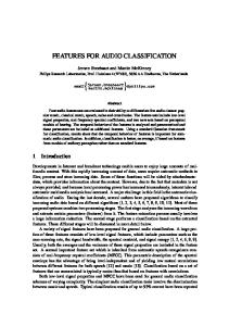
LC89091JA 6. Block Diagram
PCM / non-PCM
GPO
4
MPIO
6
Micom I/F
1
SCL
Cbit
2
SDA
3
ERR
Emphasis Default: “L”
Input Selector RXIN
LPF
Demodulation & Lock detect Data
5
7
Selector
PLL
XOUT
13 14
12
DATAO
9
MCKO
10
BCKO
11
LRCKO
Clock Clock
Selector
Divider XIN
15 SDIN
Oscillation Amplifier Power On Reset
Figure 6.1: LC89091JA Block Diagram
No.A2172-4/30
LC89091JA 7. Electrical Characteristics 7.1 Absolute Maximum Ratings Table 7.1: Absolute Maximum Ratings at GND=0V Parameter
Symbol
Conditions
Ratings
Unit
Maximum supply voltage
VDD max
7.1.1
-0.3 to 4.6
V
Input voltage
VIN
7.1.2
-0.3 to VDD max+0.3 (max.4.6Vp-p)
V
Output voltage
VOUT
7.1.3
-0.3 to VDD max+0.3 (max.4.6Vp-p)
V
Storage ambient temperature
Tstg
-55 to 125
C
Operating ambient temperature
Topr
-30 to 70
C
Maximum input/output current
IIN, IOUT
20
mA
7.1.4
7.1.1: VDD pin 7.1.2: SCL, SDA, RXIN, MPIO, XIN and SDIN pins 7.1.3: SDA, ERR, GPO, MPIO, MCKO, BCKO, LRCKO, DATAO and XOUT pins 7.1.4: Per input/output pin Stresses exceeding those listed in the Maximum Ratings table may damage the device. If any of these limits are exceeded, device functionality should not be assumed, damage may occur and reliability may be affected.
7.2 Allowable Operating Range Table 7.2: Recommended Operating Conditions at GND=0V Parameter
Symbol
Supply voltage
VDD
Input voltage range Output load capacitance
Conditions
min
typ
7.2.1
3.0
VIN
7.2.2
0
CL1
7.2.3
Output load capacitance
CL2
7.2.4
Operating temperature
Vopr
max 3.3
-30
Unit 3.6
25
V
3.6
V
20
pF
30
pF
70
C
7.2.1: VDD pin 7.2.2: SCL, SDA, RXIN, MPIO, XIN and SDIN pins 7.2.3: MCKO pin 7.2.4: Output pins expect MCKO pin Functional operation above the stresses listed in the Recommended Operating Ranges is not implied. Extended exposure to stresses beyond the Recommended Operating Ranges limits may affect device reliability.
7.3 DC Characteristics Table 7.3: DC Characteristics at Ta=-30 to 70C, VDD=3.0 to 3.6V, GND=0V Parameter
Symbol
Input, High
VIH
Input, Low
VIL
Input, High
VIH
Input, Low
VIL
Output, High
VOH
Output, Low
VOL
VDD Supply Current
IDD1
VDD Supply Current
IDD2
Conditions 7-3-1
min
max
Unit
0.7 VDD
V 0.2VDD
7.3.2
2.0
7.3.3
VDD-0.8
V V
0.8
V
0.4
V
7.3.4
20
mA
7.3.5
2
A
V
7.3.1: CMOS-compatible: XIN pin (while external clock inputs) 7.3.2: TTL-compatible: SCL, SDA, RXIN, MPIO and SDIN pins 7.3.3: IOH=-4mA, IOL=4mA: ERR, MCKO, BCKO, LRCKO, DATAO and XOUT output pins IOH=-2mA, IOL=2mA: SDA and MPIO output pins 7.3.4: Input fs: 96kHz, MCKO: 512fs output status 7.3.5: "PDMODE=1"
No.A2172-5/30
LC89091JA 7.4 AC Characteristics Table 7.4: AC Characteristics at Ta=-30 to 70C, VDD=3.0 to 3.6V, GND=0V Parameter
Symbol
min
typ
max
Unit
VDD rise slope
tVDD
-
-
100
ms
RXIN and MPIO input receive frequency
fRFS
28
-
195
kHz
RXIN and MPIO input duty factor
fRXDUY
40
50
60
%
XIN clock input frequency
fXF
-
24.576
-
MHz
MCKO clock output frequency
fMCK
4
-
50
MHz
MCKO clock output duty factor
fXMCKDUY
40
-
60
%
MCKO-BCKO output delay
tMBO
-10
-
10
ns
BCKO-LRCKO output delay
tBLO
-10
-
10
ns
BCKO-DATAO output delay
tBDO
-10
-
10
ns
LRCKO-DATAO output delay
tLDO
-10
-
10
ns
tRXDUY RXIN, MPIO
t RXDUY
Input tMC KDUY
MCKO
Output tMBO
BCKO
t MCKDUY
tMBO
Output tBLO
LRCKO
Output t LDO
DATAO
t BDO
Output
Figure 7.1: AC Characteristics
No.A2172-6/30
LC89091JA 7.5 I2C Microcontroller Interface AC Characteristics Table 7.5: AC Characteristics at Ta=-30 to 70C, VDD=3.0 to 3.6V, GND=0V Parameter
Symbol
min
max
Unit
RSTB input pulse width (L)
tRSTdw
SCL input frequency
fSCL
SCL input pulse width (L)
tSCLdw
SCL input pulse width (H)
tSCLuw
600
-
ns
Start (repeated) setup
tCSBuw
600
-
ns
SDA hold
tSDAhold
0
900
ns
SDA setup
tSDAsetup
100
-
ns
SCL-SDA rise time
tSCLSDArd
20+0.1Cb
300
ns
SCL-SDA fall time
tSCLSDAfd
20+0.1Cb
300
ns
Stop setup
tSTOPsetup
Bus open
tBUSopen
Spike pulse width
tSPKpw
-
400
600
-
kHz ns
1300
-
ns
600
-
ns
1300
-
ns
0
50
ns
Cb = total capacitance of one bus line in pF. tSTARThold
tSCLSDArd
tSCLSDAfd
tSTARTsetup tSTARThold
tSPKpw
tSTOPsetup
SCL tSCLdw
tBUSopen
tSCLuw
SDA
tSCLSDAfd
Start
tSDAhold
tSDAsetup
tSCLSDArd
Repeated Start
Stop
Start
Figure 7.2: I2C Microcontroller Interface AC Characteristics
Product parametric performance is indicated in the Electrical Characteristics for the listed test conditions, unless otherwise noted. Product performance may not be indicated by the Electrical Characteristics if operated under different conditions.
No.A2172-7/30
LC89091JA 8. System Settings 8.1 Power-On Reset The LC89091JA features a built-in power-on reset circuit, and constantly monitors the power supply status. 1s
>150s
VDD 1/2VDD Internal reset
Reset state
Figure 8.1: Power-On Reset Timing
Table 8.1: Output Port State Immediately after Power-On Reset Pin No.
Port Name
Output State
Pin No.
Port Name
Output State
3
ERR
H output
10
BCKO
XIN/4 input clock output (6.144MHz)
4
GPO
L output (Non-PCM flag)
11
LRCKO
XIN/256 input clock output (96kHz)
6
MPIO
Hi-Z output (Emphasis flag)
12
DATAO
SDIN input data output
9
MCKO
XIN input clock output (24.576MHz)
14
XOUT
XIN invert output
8.2 Register Reset and Power-Down Mode The SYSRST register resets circuits other than register. During reset period, register setting state hold and can also change. Although a system is reset by SYSRST register, the oscillation amplifier operates, and the clock is output to MCKO, BCKO and LRCKO pins. But, DATAO pin outputs "L" without relation to the setup. The system is set power-down mode by PDMODE register. During power-down mode period, register setting state hold and can also change. In power-down mode, the circuits expect a power-on reset and a microcontroller interface will be set to stop condition all the circuit operations, and the clock is not output.
No.A2172-8/30
LC89091JA 8.3 Oscillation Amplifier Pin Settings (XIN, XOUT) The LC89091JA has a built-in oscillation amplifier, and connects a quartz resonator, feedback resistor and load capacitance to XIN and XOUT to configure an oscillation circuit. The figure below shows the connection diagram. When connecting a quartz resonator, use one with a fundamental wave, and be aware that the load capacitance depends on the quartz resonator characteristics, so thorough investigation should be made. If the built-in oscillation amplifier is not used and an oscillation module is used as the clock source instead, connect the output of an external clock supply source to XIN. At this time, it is not necessary to connect a feedback resistor between XIN and XOUT. Always supply 24.576MHz clock to XIN. XIN clock is output to MCKO, BCKO and LRCKO while PLL is locked.
XIN
XOUT
XIN
XOUT
13
14
13
14 Open
1M
150 to 2.2k 24.576MHz
1p to 33pF
24.576MHz
1p to 33pF
(a) XIN and XOUT Quartz Resonator Connection Diagram
(b) XIN External Clock Input Diagram
Figure 8.2: XIN and XOUT External Circuit Connection Diagram
8.4 Loop Filter Pin Setting (LPF) The LC89091JA has a built-in VCO (Voltage Controlled Oscillator) that synchronizes with sampling frequencies from 32kHz to 192kHz and with the data with a transfer rate from 4MHz to 25MHz. The PLL is locked at 512fs. LPF is a pin for the PLL loop filter. Connect the resistor and capacitors shown in the right figure, as close to the pin as possible.
PGND
LPF
2
1 0.022 F
0.1F
100
Figure 8.3: LPF External Circuit Connection Diagram
No.A2172-9/30
LC89091JA 8.5 Clocks 8.5.1 Master Clock The clock source is selected between the following two master clocks. 1) PLL source: 512fs 2) XIN source: 24.576MHz 8.5.2 PLL Source Master Clock The PLL synchronizes with the input S/PDIF and outputs 512fs clock. The PLL clock is controlled by PLLACC, PLLDIV[1:0] and PRSEL[1:0] register settings. Normally, "PLLACC=0" is set and PLL clock is output for each input sampling frequency band. At this setting, output clock frequency fluctuation by varying the sampling frequency is kept to a narrow band, such as 512fs output when fs=32kHz to 48kHz, 256fs output when fs=64kHz to 96kHz, and 128fs output when fs=128kHz to 192kHz. When "PLLACC=0" is set, the PLL clock is set with the PLLDIV[1:0] register When "PLLACC=0" is set, during the PLL is locked, switching is not performed even when the PLLDIV[1:0] register setting is changed. These registers switching are executed when the PLL is in unlocked status. This setting becomes valid after the PLL is locked again. To set an output clock that does not depend on the S/PDIF input sampling frequency, "PLLACC=1" is set. At this setting, the clock frequency is always multiplied by a constant and output, such as output at 256fs for all sampling frequencies from 32kHz to 192kHz. When "PLLACC=1" is set, the PLL clock is set with the PRSEL[1:0] register. When "PLLACC=1" is set, PRSEL[1:0] register can be changed even PLL lock state. The change to "PLLACC=1" from "PLLACC=0" is possible even PLL lock state. But, the setting change to "PLLACC=0" from "PLLACC=1" becomes valid after the PLL is locked again. The PLL output clock setting flow is shown below. S/PDIF Input
512fs Lock detection
Unlock
Lock
PLL output Free-run
Fs calculation
“PLLACC”
1
0 Fs= 32k,44.1k,48k
No
Yes
“PLLDIV”
PLL fixation output “PRSEL=00”: 256fs “PRSEL=01”: 512fs “PRSEL=10”: 128fs Fs= 64k,88.2k,96k
No
00 or 10 Yes
01 or 11 PLL output
PLL output
256fs
512fs
“PLLDIV”
Fs= 128k,176.4k,192k
No
00 or 01 Yes
10 or 11 PLL output
PLL output
512fs
256fs
PLL output 128fs
PLL output 256fs
Figure 8.4: PLL Output Clock Flow Diagram
No.A2172-10/30
LC89091JA The PLL clock output frequencies are shown below. When "PLLACC=1" and "PRSEL[1:0]=01" (512fs) are set, 128kHz, 176.4kHz and 192kHz S/PDIF reception results in a PLL output frequency that exceeds 50MHz, so direct output to MCKO is not guaranteed. Table 8.2: PLL Clock Output Frequencies (Bold settings are initial values.) PLL clock output frequencies (MHz) S/PDIF
"PLLACC=0"
"PLLACC=1"
fs
(Fixed multiple outputs for each input fs band)
(Fixed multiple outputs of input fs)
(kHz)
"PRSEL=00"
"PRSEL=01"
"PRSEL=10"
(256fs)
(512fs)
(128fs)
8.19
8.19
16.38
4.09
22.57
11.28
11.28
22.57
5.64
24.57
12.28
12.28
24.57
6.14
16.38
32.76
32.76
16.38
32.76
8.19
22.57
22.57
45.15
45.15
22.57
45.15
11.28
24.57
24.57
49.15
49.15
24.57
49.15
12.28
16.38
16.38
16.38
16.38
32.76
65.54 *
16.38
"PLLDIV=00"
"PLLDIV=01"
"PLLDIV=10"
"PLLDIV=11"
32
16.38
8.19
16.38
44.1
22.57
11.28
48
24.57
12.28
64
16.38
88.2 96 128 176.4
22.57
22.57
22.57
22.57
45.15
90.32 *
22.57
192
24.57
24.57
24.57
24.57
49.15
98.30 *
24.57
*: Direct output to the MCKO pin is not guaranteed. 8.5.3 XIN Source Master Clock (XIN, XOUT) Supply XIN with clocks all the time to be used in the following applications. 1) Clock source when the PLL is unlocked 2) PLL lock-in support 3) Calculation of the S/PDIF input data sampling frequency 24.576MHz clock always has to supply to XIN. Normally, the oscillation amplifier automatically stops while the PLL is locked, but operation that always operates regardless of the PLL status can also be set. This is set with the AMPOPR register. The AMPOPR register must be set before S/PDIF input, or the setting must be completed while the PLL is unlocked. For fixing a system clock to a XIN clock, PLL is changed into an unlocking state. The ADMODE register always sets PLL as an unlocking state. The output clock frequency at the time of XIN source is set up with the XOUTCK register. Table 8.3: List of Output Clock Frequencies Output Pin Name
Master clock MCKO
When PLL is unlocked,
When PLL is locked,
XIN source clock (XIN input clock)
PLL source clock (Internal VCO clock)
24.576 MHz
512fs 512fs
24.576 MHz
256fs 128fs
Bit clock
6.144 MHz
BCKO
3.072 MHz
L/R clock
96 kHz
LRCKO
48 kHz
64fs
fs
No.A2172-11/30
LC89091JA 8.5.4 Output clock switching (MCKO, BCKO, LRCKO) The clock source of PLL clock or XIN clock is switched automatically according to the PLL locked or unlocked status. The output clock switches 2.7ms after the change of PLL status.
PLL status
UNLOCK
LOCK
ERRWT register
ERR MCKO BCKO LRCKO
2.7ms
XIN clock
PLL clock
(a) : Lock-in stage
PLL status
LOCK
UNLOCK
ERR
2.7ms
MCKO BCKO LRCKO
PLL clock
XIN clock
(b) : Unlock stage
Figure 8.5: Timing Chart of Output Clock Switching 8.5.5 Calculation of digital input data sampling frequency The input data sampling frequency is calculated using the XIN clock. In the "AMPOPR=0" mode (initial value) where the oscillation amplifier automatically stops according to the lock status of the PLL, the input data sampling frequency is calculated during the ERR error period and completed when the oscillation amplifier stops with holding the value. Therefore, the value remains unchanged until the PLL becomes unlocked. If the oscillation amplifier is in a continuous operation mode ("AMPOPR=1"), calculation is repeated constantly. Even if sampling changes within the PLL capture range for input data whose channel status sampling information does not change, the calculation results that follow the input data can be read. The calculation results can be readout with the microcontroller interface.
No.A2172-12/30
LC89091JA 8.6 Data 8.6.1 Reception range of S/PDIF input The input data reception range is 32kHz to 192kHz. 8.6.2 S/PDIF Input/Output pins (RXIN, MPIO, GPO) Two digital input pins and one through output pin are provided. RXIN and MPIO are TTL input level pins with 3.3V-tolerance voltage. MPSEL register needs to be set up, using MPIO as S/PDIF input. The demodulation data is selected with DINSEL register. All the S/PDIF input pins can receive 32kHz to 192kHz data. GPO is input selector output pin, and output the S/PDIF through data. The demodulated data and the through output data can be selected separately. The GPO pin output data is selected with GPOSEL[1:0] and THRSEL register. When MPIO is no-load at an output setup, don't choose MPIO by DINSEL or THRSEL register. In order to stop demodulation processing and to switch to oscillation amplifier operation, the S/PDIF input to RXIN and MPIO is stopped, or PLL is always set as an unlocking state by ADMODE register.
0 to 100
RXIN
Optical
0 to 100
LC89091JA
GPO
MPIO
Optical
Figure 8.6: S/PDIF Input Circuit Example 8.6.3 Output Data Format (DATAO) The DATAO output data format is set with DAFORM register. The initial value of the output format is I2S. The data is output synchronized with BCKIN falling edge.
L-ch
LRCKO
R-ch
BCKO MSB
DATAO
LSB
MSB
24bit
LSB 24bit
[ DAFORM=0 ] : I2S Data Output
LRCKO
R-ch
L-ch
BCKO DATAO
MSB
LSB 24bit
MSB
LSB
MSB
24bit
[ DAFORM=1 ] : MSB first Left-Justified Data Output
Figure 8.7: DATAO pin Data Output Timing
No.A2172-13/30
LC89091JA 8.6.4 Serial audio data input format (SDIN) The LC89091JA is provided with a serial data input pin of SDIN. The format of the serial audio data input to SDIN and the demodulation data output format must be identical. The SDIN data to be input must be synchronization with the BCKO and LRCKO clocks. The data input from the SDIN pin is through-output to the DATAO pin. Data format conversion cannot be performed. Normally, SDIN input data is output to DATAO pin when PLL is unlocked. But, with the ADMODE register setting, the SDIN input data is output to DATAO regardless of the locked/unlocked status of the PLL. The SDIN pin must be connected to GND when it is not used.
24bit SDIN
MSB
24bit LSB
MSB
L-ch
LRCKO
LSB
R-ch
BCKO MSB
DATAO
LSB
MSB
LSB
2
[ DAFORM=0 ] : I S Data Input
24bit SDIN
MSB
LRCKO
24bit LSB
MSB
LSB
MSB
R-ch
L-ch
BCKO DATAO
MSB
LSB
MSB
LSB
MSB
[ DAFORM=1 ] : MSB first Left-Justified Data Input
Figure 8.8: SDIN pin Data Input Timing
No.A2172-14/30
LC89091JA 8.6.5 Output data switching (SDIN, DATAO) DATAO outputs demodulation data when the PLL is locked, and outputs SDIN input data when the PLL is unlocked. This output is automatically switched according to the PLL locked/unlocked status. When SDIN input data is selected, SDIN input data must synchronize with clock source. DATAO output switches via a mute period. It adjusts by ERRWT register during the mute period at the time of PLL lock-in process. It adjusts by DATWT register during the mute period at the time of PLL unlock process With the DATMUT setting, the DATAO output data can be also muted forcibly. NPMODE register can be muted the DATAO output data, when non-PCM data is received. Non-PCM data applies to the state of the channel status bit 1.
PLL status
UNLOCK
~~
LOCK ERRWT register
ERR ERR DATAO
ERRSEL=0
~~
ERRSEL=1
~~
SDIN data
Muted
Demodulation data
~~
(a) : Lock-in stage
PLL status
LOCK
UNLOCK
~~
DATWT register
ERR ERR DATAO
~~
ERRSEL=0
~~
ERRSEL=1
Demodulation data
Muted
SDIN data
~~
(b) : Unlock stage
Figure 8.9: Timing Chart of DATAO Output Data Switching
No.A2172-15/30
LC89091JA 8.7 Error Output Processing (ERR) The ERR output can be selected the following outputs by the ERRSEL register. 8.7.1 Lock Error and Data Error Output ("ERRSEL=0") The ERR pin outputs an error flag when PLL lock error or data error occurs. The ERR is output synchronizing with LRCKO and can be readout with the microcontroller interface. 8.7.1.1 PLL Lock Error The PLL gets unlocked for input data that lost bi-phase modulation regularity, or input data for which preambles B, M and W cannot be detected. However, even if preambles B, M and W are detected if the timing does not conform to the IEC60958, the PLL get unlocked and processed. For example, period of preamble B is not every192 frames. The ERR outputs "H" when the PLL lock error occurs. The ERR outputs "L" when the data demodulation returns normal and "H" is held for somewhere between 3m to 36ms. This holding time is set with the ERRWT register. Table 8.4: ERR Release Maintenance Period after a PLL Locks S/PDIF input sampling frequency (kHz)
ERR release maintenance period after a PLL locks (ms) "ERRWT=0"
"ERRWT=1"
32
18
36
44.1
13
26
48
12
24
88.2
6.5
13
96
6
12
176.4
3.3
6.5
192
3
6
8.7.1.2 Input Data Parity Error An odd number of errors among parity bits in input data and input parity errors are detected. The ERR outputs "H" when an input parity error occurs. When an input parity error occurs, output data is replaced to the data of one frame ago. However, when having received non-PCM data, data does not replace. In this case, data including an error is output. 8.7.1.3 Other Errors Even if ERR turns to "L", the channel status bits of 24 to 27 (sampling frequency information) are always fetched and the data of the previous block is compared with the current data. Moreover, the input data sampling frequency is calculated from the fs clock extracted from the input data, and the fs calculated value is compared in the same way as described above. If any difference is detected in these data, ERR is instantly made "H" and the same processing as for PLL lock errors is carried out. In this case, the clock source is switched to XIN and processing is restarted at lock status identification processing. In order to support sources with a variable fs (for example, a CD player with a variable pitch function), any change in fs made after ERR is reset is not reflected on ERR unless such change exceeds the PLL capture range. 8.7.2 DATAO data Mute Signal Output ("ERRSEL=1") This mode outputs the state of the audio data outputted from the DATAO pin. (See “Figure 8.9”) A mute processing setup at the time of non-PCM audio data reception ("NPMODE=1")) is also reflected. Table 8.5: DATAO Output State Signal Output ERR output
DATAO output conditions
L
Muted
H
Outputted
No.A2172-16/30
LC89091JA 8.8 General Purpose Output (GPO) The GPO output can be selected the following outputs by the GPOSEL[1:0] register. 8.8.1 Channel Status Bit 1 Output ("GPOSEL[1:0]=00") The initial mode outputs bit 1 of the channel status that indicates whether the input bi-phase data is PCM audio data. It is immediately output upon detection of ERR even during an error output period. Table 8.6: Channel Status Bit 1 Output GPO output
GPO output conditions
L
Audio sample word represents linear PCM samples (Bit1=L)
H
Audio sample word used for other purposes (Bit 1=H)
8.8.2 S/PDIF Through-output ("GPOSEL[1:0]=01") The data selected by the S/PDIF input selector (DINSEL register) is output. The output data is selected with the THRSEL register. Table 8.7: Output of S/PDIF data GPO output
GPO output conditions
RXIN or MPIO input data
"GPOSEL[1:0]=01"
8.8.3 Microcontroller Register Output ("GPOSEL[1:0]=10 or 11") This mode outputs a serial data that is set by the microcontroller interface. It can be used as a control signal of peripheral circuitry. Table 8.8: Microcontroller Register Output GPO output
GPO output conditions
L
"GPOSEL[1:0]=10"
H
"GPOSEL[1:0]=11"
LC89091JA IN0 Out
RXIN
IN1 157 etc
GPO
IN0 HCU04
Out
MPIO
IN1 HCU04
157 etc
Figure 8.10: GPOSEL [1:0] register Example of Use
No.A2172-17/30
LC89091JA 8.9 Multi Purpose Input/Output (MPIO) MPIO can be selected the following input/output by the MPSEL register. MPIO needs a pull-up resistor when set to the output. When not using MPIO, it uses no connecting (open state). However, don't choose MPIO by DINSEL or THRSEL register. 8.9.1 Pre-emphasis Flag Output ("MPSEL=0") The initial mode outputs pre-emphasis of the channel status that indicates whether there is 50/15s emphasis parameter for consumer. MPIO becomes a Hi-Z output when an emphasis signal is not detected. For this reason, it connects with a pull-up resistor. The example of use is shown below Table 8.9: Pre-emphasis Flag Output MPIO output
MPIO output conditions
Hi-Z (H**)
No pre-emphasis
L
50/15s pre-emphasis
**: When MPIO connects with a pull-up resistor
LC89091JA
DAC
De -emphasis
MPIO
Figure 8.11: MPIO Output Example of Use (Pre-emphasis Output)
8.9.1 S/PDIF data Input ("MPSEL=1") MPIO can be used as S/PDIF input terminal by "MPSEL=1". MPIO immediately after power-on is set as an output state. For this reason, before input all the S/PDIF signals, MPIO is set as an input state by MPSEL register. If S/PDIF signal input (RXIN input) before MPSEL register setup and preemphasis flag is detected, MPIO output will short-circuit with peripheral circuitry. Therefore, before S/PDIF signal input, MPIO setup must be complete.
No.A2172-18/30
LC89091JA 9. Microcontroller Interface The LC89091JA is controlled via I2C (Fast-mode, 400kHz). 9.1 Terminal Setup (SCL, SDA) The pull-up resistor is connected to SCL and SDA pins. The resistor should take current and timing into consideration enough. If the clock line will not be Hi-Z state, the pull-up resistor of SCL may delete. When not using microcontroller, SCL and SDA make GND connection. In this case, initial value of register is set up. 9.2 Data Transfer I2C slave transceiver interface is based on ver2.1 (HS mode un-corresponding). At first, input Start condition and Slave-address, an acknowledge generates, WRITE operation and READ operation (input Register-address and Control-data) is executed. After the command execution, input Stop condition. SDA line state must be constant while SCL is "H". State change on SDA line is restricted while SCL line is "L". If SDA data changes while SCL line is "H", it will be recognized as Start condition or Stop condition.
SDA
SCL data line stable: data valid
change of data allowed
Figure 9.1: Data transfer on I2C bus 9.3 Start and Stop Condition The Start condition is generated by the transition of "H" to "L" on SDA line while SCL line is "H". The Stop condition is generated by the transition of "L" to "H" on SDA line while SCL line is "H".
SDA
SCL S
P
Start condition
Stop condition
Figure 9.2: Start and Stop Condition 9.4 Acknowledge After receiving bits (1 byte) of data, SDA line is released, LC89091JA will stabilize SDA line in "L" state. This operation is called "acknowledgement". The LC89091JA generates an acknowledgement upon receipt of Start condition and Slave-address. Furthermore, for a WRITE instruction, an acknowledgement is generated whenever receipt of each byte is completed. For a READ instruction, succeeded by generation of an acknowledgement, the LC89091JA releases the SDA line after outputting data at the designated address, and it monitors the SDA line condition. When the microcontroller generates an acknowledgement without sending Stop condition, the LC89091JA outputs data at the next address location. When no acknowledgement is generated, the LC89091JA ends data output (not acknowledged).
No.A2172-19/30
LC89091JA 9.5 Slave-address The Slave-address inputs after the Start condition. The Slave-address is configured with the upper 7-bits. Data of the upper 5-bits is Device code that is input "00100". The next 2-bits are Device address that is input "10". When the R/W bit is "1", the READ instruction is executed, and when it is "0", the WRITE instruction is executed. Device code
0
0
1
Device address
0
0
1*
0*
R/W
Slave address
Figure 9.3: Slave-address Configuration 9.6 Register-address After transmitting 1 byte of data containing Slave-address, Register-address is set up from next byte. Register address
0
0
0
0
0
A2
A1
A0
D1
D0
Figure 9.4: Register-address Configuration
9.7 Control Data The control data inputs after Register-address transmission. The control data (D7 to D0) is configured with MSB first. Control data
D7
D6
D5
D4
D3
D2
Figure 9.5: Control Data Configuration
No.A2172-20/30
LC89091JA 9.8 WRITE Operation When the R/W bit is "0", the WRITE instruction is executed. After Start condition input, Slave-address (R/W=0) and Register-address are input one by one. After an acknowledge is generated, the write data is taken in by SCL in front of an acknowledge clock pulse. When the Slave-address is differ, an acknowledge is not generated, SDA line will be in an open state. In this case, it has to input from Start conditions (S). SDA
0
0
1
0
0
1
0
0
0
0
0
0
A3
A2
A1
A0
D7
D6
D5
D4
D3
D2
D1
D0
SCL S Start condition
P Slave address
R/W
ACK
Register address (n)
ACK
Control data (n)
ACK
Stop condition
Figure 9.6: I2C Data Write Timing Chart (Byte Write)
After receipt of 8 bits (1 byte) data, when data (1 byte) transmits further without sending Stop conditions after an acknowledge generation, the Register-address counter is incremented by one and data is stored in the next address. If an address value becomes 08h address, address counter will "rolls over" to 00h address and data is stored from 00h and the previous data will be overwritten.
D0
ACK
D1
D2
D3
D4
D5
D6
D7
D0
D1
Data (n+x)
ACK
D2
D3
D4
D5
D6
D7
D0
ACK
Data (n+2)
D1
D2
D3
D4
D5
D6
D7
D0
ACK
D1
Data (n+1)
D2
D3
D4
D5
D6
A0
D7
A1
Data (n)
ACK
0 0 0 0
A2
S 0 0 1 0 0 1 0 0
A3
SDA
Register address (n)
R/W
ACK
Slave address
P
Figure 9.7: I2C Data Write Timing Chart (Page Write)
No.A2172-21/30
LC89091JA 9.9 READ Operation When the R/W bit is "1", the READ instruction is executed. After Start condition input, Slave-address (R/W=0) and Register-address are input one by one. After an acknowledge is generated, Start condition (Sr) and Slave-address (R/W=1) input again. And, after an acknowledge is generated, the data of the Register-address specified is output. If the microcontroller does not generate an acknowledge but generate the Stop condition, the LC89091JA discontinues transmission.
SDA
0
0
1
0
0
1
0
0
0
0
0
0
A3 A2 A1 A0
0
0
1
0
0
1
0
1
D7 D6 D5 D4 D3 D2 D1 D0
SCL S Start condition
Sr Slave address
R/W ACK
Register address
P
ACK
Slave address
R/W ACK
Control data
ACK
Stop condition
Figure 9.8: I2C Data Read Timing Chart (Random Read)
If a microcontroller returns an acknowledge after 8 bits (1 byte) data output, the data (1 byte) of the next address will be read continuously. If an address value becomes 08h address, the next address will be read from 00h data one by one. If a microcontroller does not generate an acknowledge but generate the Stop condition, the LC89091JA discontinues transmission.
D0
ACK
D1
D2
D3
D4
D5
D6
D7
D0
D1
Data (n+x)
ACK
D2
D3
D4
D5
D6
D7
D0
ACK
D1
Data (n+1)
D2
D3
D4
D5
D6
D7
R/W
Sr 0 0 1 0 0 1 0
Data (n)
ACK
A0
A1
0 0 0 0
Slave address
ACK
R/W
S 0 0 1 0 0 1 0
ACK
SDA
A3 A2
Register address
Slave address
P
Figure 9.9: I2C Data Read Timing Chart (Sequential Read)
No.A2172-22/30
LC89091JA 9.10 Registers 9.10.1 Register Map Table 9.1: Register Map Setting Item
R/W
Adr
D7
D6
System
R/W
00h
"0"
MPSEL
Clock
R/W
01h
"0"
"0"
Data
R/W
02h
NPMODE
ERRSEL
D5
D4
D3
D2
D1
D0
DATWT
ERRWT
ADMODE
AMPOPR
PDMODE
SYSRST
XOUTCK
PRSEL1
PRSEL0
PLLDIV1
PLLDIV0
PLLACC
GPOSEL1
GPOSEL0
DATMUT
THRSEL
DINSEL
DAFORM
Fs calculation
R
03h
0
0
0
ERRFLG
FSC3
FSC2
FSC1
FSC0
Channel status
R
04h
CS7
CS6
CS5
CS4
CS3
CS2
CS1
CS0
R
05h
CS15
CS14
CS13
CS12
CS11
CS10
CS9
CS8
R
06h
CS23
CS22
CS21
CS20
CS19
CS18
CS17
CS16
R
07h
CS31
CS30
CS29
CS28
CS27
CS26
CS25
CS24
R
08h
CS39
CS38
CS37
CS36
CS35
CS34
CS33
CS32
"0" is a reserved bit. Always must be set to "0".
No.A2172-23/30
LC89091JA 9.10.2 Details of Registers Address: 00h; System Setting 00h
D7
D6
D5
D4
D3
D2
D1
D0
Register name
"0"
MPSEL
DATWT
ERRWT
ADMODE
AMPOPR
PDMODE
SYSRST
Initial value
0
0
0
0
0
0
0
0
Setting
R
R/W
R/W
R/W
R/W
R/W
R/W
R/W
SYSRST
System reset 0: Don’t reset (initial value) 1: Reset all circuits other than registers
PDMODE
Power down mode setting 0: Normal operation (initial value) 1: Power down mode (clock operation stop)
AMPOPR
Oscillation amplifier operation setting 0: Automatic stopping of oscillation amplifier while PLL is locked (initial value) 1: Permanent continuous operation
ADMODE
S/PDIF reception refusal mode setting 0: Normal operation (initial value) 1: Always PLL unlock state
ERRWT
ERR wait time setting after PLL is locked 0: Error is canceled after 3 occurrences of preamble B are counted (initial value) 1: Error is canceled after 6 occurrences of preamble B are counted
DATWT
DATAO wait time setting after PLL is unlocked 0: Mute is canceled after about 5.4 ms (initial value) 1: Mute is canceled after about 342ms
MPSEL
MPIO pin input/output setting 0: Pre-emphasis flag output (initial value) 1: S/PDIF input
No.A2172-24/30
LC89091JA Address: 01h; Clock Setting 01h
D7
D6
D5
D4
D3
D2
D1
D0
Register name
PLLACC
"0"
"0"
XOUTCK
PRSEL1
PRSEL0
PLLDIV1
PLLDIV0
Initial value
0
0
0
0
0
0
0
0
Setting
R
R
R/W
R/W
R/W
R/W
R/W
R/W
PLLACC
PLL clock lock frequency setting 0: Automatic control (initial value) 1: Manual setting
PLLDIV[1:0]
PLL lock time MCKO output setting when PLLACC is set to "0" 00: 512fs output: When receiving 32kHz, 44.1kHz, 48kHz (initial value) 256fs output: When receiving 64kHz, 88.2kHz, 96kHz 128fs output: When receiving 128kHz, 176.4kHz, 192kHz 01: 256fs output: When receiving 32kHz, 44.1kHz, 48kHz 256fs output: When receiving 64kHz, 88.2kHz, 96kHz 128fs output: When receiving 128kHz, 176.4kHz, 192kHz 10: 512fs output: When receiving 32kHz, 44.1kHz, 48kHz 512fs output: When receiving 64kHz, 88.2kHz, 96kHz 128fs output: When receiving 128kHz, 176.4kHz, 192kHz 11: 256fs output: When receiving 32kHz, 44.1kHz, 48kHz 512fs output: When receiving 64kHz, 88.2kHz, 96kHz 128fs output: When receiving 128kHz, 176.4kHz, 192kHz
PRSEL[1:0]
PLL lock time MCKO output setting when PLLACC is set to "1" 00: 256fs output (initial value) 01: 512fs output 10: 128fs output 11: Reserved
XOUTCK
XIN clock output setting when PLL is unlocked 0: MCKO=24.576MHz, BCKO=6.144MHz, LRCKO=96kHz (initial value) 1: MCKO=24.576MHz, BCKO=3.072MHz, LRCKO=48kHz
No.A2172-25/30
LC89091JA Address: 02h; Data setting 02h
D7
D6
D5
D4
D3
D2
D1
D0
Register name
NPMODE
ERRSEL
GPOSEL1
GPOSEL0
DATMUT
THRSEL
DINSEL
DAFORM
0
0
0
0
0
0
0
0
R/W
R/W
R/W
R/W
R/W
R/W
R/W
R/W
Initial value Setting
DAFORM
Audio data output format setting 0: I2S data output (initial value) 1: 24-bit MSB first, left-justified data output
DINSEL
Data demodulation input setting 0: RXIN (initial value) 1: MPIO (when "MPSEL=1")
THRSEL
GPO output data setting when "GPOSEL[1:0]=01" 0: RXIN (initial value) 1: MPIO (when "MPSEL=1")
DATMUT
DATAO pin output setting 0: Output SDIN data while PLL is unlocked (initial value) 1: Mute, "L" output
GPOSEL[1:0]
GPO output data setting 00: Channel status bit 1 output (initial value) 01: Input S/PDIF through output 10: "L" output 11: "H" output
ERRSEL
ERR pin output setting 0: PLL lock error or transfer data parity error output (initial value) 1: DATAO data mute signal output
NPMODE
DATAO pin output setting when S/PDIF non-PCM data is received 0: Output (initial value) 1: Mute, "L" output
When MPIO is no-load at an output setup, don't choose MPIO by DINSEL or THRSEL register. DATAO is muted when non-PCM data is detected at "NPMODE=1". But, due to it is not a data error, ERR output PLL lock state ("L" output).
No.A2172-26/30
LC89091JA Address: 03h; Input fs calculation value D7
D6
D5
D4
D3
D2
D1
D0
Register name
03h
0
0
0
ERRFLG
FSC3
FSC2
FSC1
FSC0
Setting
R
R
R
R
R
R
R
R
FSC[3:0]
ERRFLG
Input data fs calculation result read 0000: 44.1kHz 0001: Out of range 0010: 48kHz 0011: 32kHz 0100: 0101: 0110: 0111: 1000: 88.2kHz 1001: 1010: 96kHz 1011: 64kHz 1100: 176.4kHz 1101: 128kHz 1110: 192kHz 1111: ERR pin output read (It can be read when "ERRSEL=1") 0: No transfer error while PLL is locked 1: Transfer error exists or PLL is unlocked
No.A2172-27/30
LC89091JA Address: 04h to 08h; Channel status information (read only) Address
D7
D6
D5
D4
D3
D2
D1
D0
04h
CS7
CS6
CS5
CS4
CS3
CS2
CS1
CS0
05h
CS15
CS14
CS13
CS12
CS11
CS10
CS9
CS8
06h
CS23
CS22
CS21
CS20
CS19
CS18
CS17
CS16
07h
CS31
CS30
CS29
CS28
CS27
CS26
CS25
CS24
08h
CS39
CS38
CS37
CS36
CS35
CS34
CS33
CS32
Table 9.2: Channel Status Register Contents Adr
Reg
CS Bit
04h
CS0
bit0
Application
CS1
bit1
Control
CS2
bit2
CS3
05h
06h
Description
Adr
Reg
CS Bit
07h
CS24
bit24
CS25
bit25
CS26
bit26
bit3
CS27
bit27
CS4
bit4
CS28
bit32
CS5
bit5
CS29
bit33
CS6
bit6
CS30
bit30
CS7
bit7
CS31
bit31
Not defined
CS8
bit8
CS32
bit32
CS9
bit9
CS33
bit33
CS10
bit10
CS34
bit34
CS11
bit11
CS35
bit35
CS12
bit12
CS36
bit36
CS13
bit13
CS37
bit37
CS14
bit14
CS38
bit38
CS15
bit15
CS39
bit39
CS16
bit16
CS17
bit17
CS18
bit18
CS19
bit19
CS20
bit20
CS21
bit21
CS22
bit22
CS23
bit23
Category code
08h
Description Sampling frequency
Clock accuracy
Not defined
Bit width
Original sampling frequency
Source number
Channel number
For details, check the IEC60958 Specifications
No.A2172-28/30
LC89091JA 10. Application Circuit Example Analog Data Input / Output
(PLL error flag)
LC89091JA
(Non-PCM flag) to DSP R2 Digital Data Input
R3
1 SCL
VDD 16
2 SDA
SDIN 15
3 ERR
XOUT 14
4 GPO
XIN 13
5 RXIN
DATAO 12
6 MPIO
LRCKO 11
7 LPF
BCKO 10
8 GND
MCKO 9
R2
Audio CODEC
R2 DSP
C3
to Audio CODEC
SSOP-16 (225mil)
(Emphasis flag)
R0
R4
R1 24.576MHz
C2
C0
C1
C1
(1) Example of microcontroller interface is not used
Analog Data Input / Output
Controller R3
LC89091JA
R2 S/PDIF Output
S/PDIF Input
1 SCL
VDD 16
2 SDA
SDIN 15
3 ERR
XOUT 14
4 GPO
XIN 13
5 RXIN
DATAO 12
6 MPIO
LRCKO 11
7 LPF
BCKO 10
8 GND
MCKO 9
R2
Audio CODEC
R2 DSP
C3
SSOP-16 (225mil)
R0
R4
R1 24.576MHz
C2
C0
C1
C1
(2) Example of microcontroller interface is used
Element Symbol
Recommended Parameter
Application
Remarks
C0
0.01F to 0.1F
Power supply de-coupling
Ceramic capacitor
R0
1M
Oscillation amplifier feedback
R1
150 to 2.2k
Oscillation amplifier current limit
C1
1pF to 33pF
Quarts resonator load
R2
0 to 100
Damping resistor
R3
10k to 100k
Pull-up resistor
R4
100
PLL loop filter
C2
0.1F
PLL loop filter
See 8.4
C3
0.022F
PLL loop filter
See 8.4
Ceramic capacitor with NP0 characteristics
See 8.4
Figure 10.1: LC89091JA Application Circuit Example
No.A2172-29/30
LC89091JA ORDERING INFORMATION Device LC89091JA-AH
Package SSOP16(225mil) (Pb-Free / Halogen Free)
LC89091JA-H
SSOP16(225mil) (Pb-Free / Halogen Free)
Shipping (Qty / Packing) 2000 / Tape & Reel 90 / Fan-Fold
ON Semiconductor and the ON logo are registered trademarks of Semiconductor Components Industries, LLC (SCILLC). SCILLC owns the rights to a number of patents, trademarks, copyrights, trade secrets, and other intellectual property. A listing of SCILLC’s product/patent coverage may be accessed at www.onsemi.com/site/pdf/Patent-Marking.pdf. SCILLC reserves the right to make changes without further notice to any products herein. SCILLC makes no warranty, representation or guarantee regarding the suitability of its products for any particular purpose, nor does SCILLC assume any liability arising out of the application or use of any product or circuit, and specifically disclaims any and all liability, including without limitation special, consequential or incidental damages. “Typical” parameters which may be provided in SCILLC data sheets and/or specifications can and do vary in different applications and actual performance may vary over time. All operating parameters, including “Typicals” must be validated for each customer application by customer’s technical experts. SCILLC does not convey any license under its patent rights nor the rights of others. SCILLC products are not designed, intended, or authorized for use as components in systems intended for surgical implant into the body, or other applications intended to support or sustain life, or for any other application in which the failure of the SCILLC product could create a situation where personal injury or death may occur. Should Buyer purchase or use SCILLC products for any such unintended or unauthorized application, Buyer shall indemnify and hold SCILLC and its officers, employees, subsidiaries, affiliates, and distributors harmless against all claims, costs, damages, and expenses, and reasonable attorney fees arising out of, directly or indirectly, any claim of personal injury or death associated with such unintended or unauthorized use, even if such claim alleges that SCILLC was negligent regarding the design or manufacture of the part. SCILLC is an Equal Opportunity/Affirmative Action Employer. This literature is subject to all applicable copyright laws and is not for resale in any manner.
PS No.A2172-30/30