Chop Source Frame Jig Assembly Instructions
These are the instructions on how to assemble the Chop Source Frame Jig Kit. If you have any questions regarding any part of the assembly process after reading these instructions, please email
[email protected]. The steps to assembling the jig are listed below. Some steps may not apply depending on which fixtures you purchased. Step 1. Step 2. Step 3. Step 4. Step 5. Step 6. Step 7. Step 8. Step 9. Step 10.
Cut tubing to length Assemble jig uprights to the main rails Assemble neck fixture Assemble axle plate fixture Assemble center fixture Assemble feet Assemble rotisserie brackets Weld spacers into stand uprights Assemble stand Lift jig into stand
Jig Plans The drawing on page 2 shows the complete jig with rotisserie stand. The drawing on page 3 shows the table-top version of the jig. The top of page 4 has a picture of a frame in the jig. See Step 1 for more information on the lengths of structural tubing required for the jig.
1
70 in
CHOP SOURCE FRAME JIG
36 in
24 in
3 in 8 in
38 in
16 in
72 in
84 in
2
CHOP SOURCE FRAME JIG
36 in
24 in
72 in
3
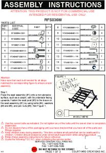
General Guidelines Hand-tighten all fasteners during assembly and torque fasteners to 20 ft-lbs when instructed. Step 1: Cut tubes to length Several lengths of 2"x2" square or 2"x3" rectangle tubing with a 1/8" (or 11ga / .120") wall are required to complete the jig. This should be available locally at a metal supply store or welding/fabrication shop. The tubes are typically available in 20'-24' lengths and many times the store/shop will cut them to size for an additional fee. The lengths provided below are just a guideline that should work for many different styles of frames and they should be adjusted to suit your needs. See the FAQ at the end of the instructions for more details on mainrail lengths.
4
Part Table-Top Jig (Frame Jig Kit - Standard) Main rails for jig Upright for neck fixture Upright for axle plate fixture Spacer for center fixture internal Center fixture external (optional) Legs* Total Rotisserie Stand Main rails for stand Uprights for stand Upright for rear rotisserie bracket Total * A table-top jig will work fine with 20" legs.
Qty Required
Length
2 1 1 1 1 2 -
6' 3' 2' 6" ≈1' 2' 21'6-22'6"
2 2 1 -
7' 3'2" 1'4" 21'8"
If you decided to extend the main rails for the jig, you'll need to extend the rails for the stand by an equal amount. Step 2: Assemble jig uprights to the main rails Assemble the basic structure for the jig using two base clamps, 2 main rails, the upright for the neck fixture, and the upright for the axle plate fixture. If you are using a rotisserie stand, you'll also need the upright for the rear rotisserie bracket and one additional base clamp. The uprights should extend below the main rails by 1" and the upright for the neck fixture and rear rotisserie bracket should be spaced inward 1" from the end of the main rails. Each base clamp uses four 7/16" x 8" bolts (each with two washers, a lock washer, and a nut). Square the uprights and torque all of the 7/16" bolts to 20 ft-lbs. Step 3: Assemble neck fixture The neck fixture consists of two plates, the rod that holds the neck cones (neck rod), and the block the neck rod attaches to (rod block). Use three 7/16" x 3-1/2" bolts (each with two washers, a lock washer, and a nut) to attach the neck fixture plates to the 3' upright. The rod block consists of 6 plates that fit together like a puzzle and it is used to hold and align the neck rod. The rod block ships assembled with a zip tie holding it together. Cut the zip tie and while holding the block together from the sides, insert the 3/4" x 16.5" threaded rod through the 3/4" holes. Spin a 3/4" nut onto the bottom of the rod and slide the neck rod up into the block. The bottom nut will recess into the block and be held from turning by 2 sides of the block. Spin a nut down the top of the rod and tighten it securely while holding the rod and block. Look through the lower 5/8" pivot hole to make sure the neck rod will not block the lower pivot bolt. The sides of the rod block will be held in place once it is bolted between the neck fixture plates. You do not need to weld the block. You may tack weld or fully weld the block, but be careful to not weld where the block makes contact with the neck fixture plates. Use two 5/8" x 4" bolts (each with two washers, a lock washer, and a nut) to mount the rod block between the neck fixture plates. Thread another 3/4" nut down the neck rod (optional), followed by a washer and neck cone. Once the frame is in the jig, you'll add the top cone, a 3/4" washer, and a 3/4" nut.
5
6
Step 4: Assemble axle plate fixture Use three 7/16" x 3-1/2" bolts (each with two washers, a lock washer, and a nut) to attach the axle plate fixture to the 2' upright. The fixture has holes and slots for 3/4", 1", and 5/8" threaded rods (in that order from top to bottom). If you purchased a threaded rod and spacer kit, you will have two 14" threaded rods, one 2" spacer, and just over 16" of spacer material (two 8-1/4" pieces). The 2" spacer goes between the fixture plates on the rod furthest from the upright. The rod closest to the upright does not have a spacer between the plates. To determine the length of the four spacers that go on the outside of the fixture plates, take the distance needed between the axle plates, subtract 2-1/2" (outside width of plates), and divide by two. Cut four spacers to that length. For example, if you want your axle plates to be 8-1/2" apart, you would cut four 3" spacers… (8.5-2.5) / 2 = 3. The spacer material provided allows for axle plate spacing up to 10-1/2". Use .120" DOM tube (.120" wall) if you need additional spacer material.
7
Step 5: Assemble center fixture Center fixture internal: Use four 7/16" x 8" bolts (each with two washers, a lock washer, and a nut) to attach the center fixture plates to the main rails of the jig. Place a 6" spacer cut from either 2"x2" or 2"x3" tubing between the lower rails in the same location as the center fixture (see second picture below). Use the 6" spacer (3/4" o.d. round tubing) between the tabs of the center fixture plates. From the shorter (3/4" o.d. round tubing) spacer, cut two spacers for the outside of the plates so the total width matches the inside of the mounts on the frame you are supporting. Two ¼" spacers ("donuts") are provided for convenience if you are mounting a Yamaha XS650 frame that needs 7" of spacing.
8
Center fixture external: The center fixture external is created using a piece of 2"x2" (or 2"x3") tubing placed on top of the main rails (perpendicular). The two triangle tabs should be spaced wide enough to bolt to the outside of the mounts on the frame you are supporting. The tabs are cut to the desired height and welded to the tubing. Drill a 1/2" hole in the bottom of the each piece of tubing centered between the tabs (on opposite side of the tabs). Weld a 7/16" nut centered over the hole. Use the 1-1/2" x 5" rectangle plate with a 7/16" x 31/2" bolt (or 7/16" x 2-1/2" bolt if you have 2"x2" main rails) with a lock washer and washer to hold the fixture to the rails. The rectangle plate attaches to the bottom of the rails.
Step 6: Assemble feet Dill a 1/2" hole centered on one side of both pieces of tubing used for the legs. On the opposite side of each of the tubes, drill a 1/2" hole 1" from each end of each tube (centered width wise). Weld 7/16" nuts over each hole. Thread nuts onto the four 2-1/2" carriage bolts and thread them into the nuts welded to the ends of the leg tubes. These serve as adjustable legs. Use two 1-1/2"x5" rectangle plates with 7/16" x 3-1/2" bolts (or 7/16" x 2-1/2" bolts if you have 2"x2" main rails) with a lock washer and washer to hold the feet to the main rails of the jig. The feet go under the rails and rectangle plates attach to the top of the rails. If you are using a stand, the feet will attach to the main rails of the stand instead. The picture below shows the top and bottom sides of the tubes used for the feet. If you are using the jig on a table, level the jig and torque all nuts to 20ft-lbs.
9
Step 7: Assemble rotisserie brackets Attached the third upright for the rear rotisserie bracket to the main rails of the jig using one base clamp. The base clamps uses four 7/16" x 8" bolts (each with two washers, a lock washer, and a nut). Square the upright and torque the 7/16" bolts to 20 ft-lbs. Attach the clamp part of the rotisserie bracket (two square plates) to the front upright on the jig using four 41/2" bolts. If you have 2"x2" uprights, use the 3-1/2" bolt provided instead. Install a lock washer on each bolt followed one washer and then insert the bolts into the square plate. Attach it to the upright from the inside and slide the second square plate over the bolts followed by a coupling nut on each bolt. The center of the bracket should be about 8" from the top of the main rails. The coupling nuts should face out from the jig. Attach the round rotisserie plate to the clamp using four 1" bolts with washers. Repeat for the rear upright. Torque all bolts to 20ft-lbs while holding the coupling nuts with a wrench.
10
Step 8: Weld spacers into stand uprights On both of the uprights for the stand, drill a 7/8" hole 1" from one end, and drill another 7/8" hole 4" from the same end (step drill bits work great for the 7/8" holes). The holes should be 3" apart and centered width wise on the tube. Flip the tube over and repeat for the opposite side of the tube (not the opposite end). You are creating two 7/8" through holes in each upright. Weld the spacers that hold the 5/8" bolts for the rotisserie brackets into the uprights with 1/2" of the spacer protruding from the inside of the upright. If you are using 2"x2" uprights for the stand, leave 1" of the spacer protruding from the inside of the upright. Step 9: Assemble stand Assemble the stand in a similar fashion to assembling the main jig using two base clamps. The uprights should be spaced far enough apart so the ends of the rotisserie brackets will just fit between the spacers welded into the uprights. Attach the feet to the stand. Square the uprights and torque all of the 7/16" bolts to 20 ft-lbs. Level the stand Step 10: Lift jig into stand Insert two 5/8" x 5" bolts halfway into the spacers in each of the stand uprights. With the help of a friend or two, lift the jig into the stand and slide the bolts through the spacers and into the round rotisserie plate. The top bolt on each upright will go through the middle hole of the round rotisserie plate. Use two 5/8" SAE washers (smaller than the 5/8" washers used in the neck fixture) and a 5/8" nut to secure each 5/8" bolt. You're now ready to use the jig. If you have any questions regarding any part of the assembly process, please email
[email protected]
11
Frequently Asked Questions: Question: How long should I make the main rails for the jig? Answer: That depends on the type of frame you want to put in the jig or what type of frame you want to build. Obviously, if you're building a drag bike you're going to need a longer jig than someone who is putting a hardtail on an old Triumph. These instructions are based on a jig with 6' main rails. That will work for many different frames. The frame in the picture on page 4 is a Yamaha XS650 frame and 6' rails will accommodate up to an 11" stretch with the axle plate fixture pointed to the rear. You'll get over 17" of stretch if using the jig without a stand since the rear upright for the rotisserie bracket won't be in the way. If you want a longer jig, you can make the rails for jig and stand longer. You could build the jig for the projects you have in mind, and purchase new rails later if needed. One of the nice things about a bolt together jig is that you can easily make the jig longer. You won't have to cut it apart and then weld it back together. Tips: When drilling holes, use a center punch so your bit doesn't wander, then drill a small pilot hole. Use a step drill bit to enlarge the hole to the required size. Use oil to keep the drill bit cool. Level the jig before starting your project. Digital angle finders work well for this. Keep the neck and center fixtures somewhat loose if you are trying to put a frame into the jig. Since the center fixtures are a fixed height, to lower a bike in the rear, you raise the axle plate fixture. If you have a complete bike and you want to modify the frame in the jig, take measurements from the bike before you take it apart. Measure the rake of the head tube, and with a rider sitting on the bike, the distance from the head tube to the ground, the distance from the lower frame rails to the ground, and the distance from the rear axle to the ground. You might want those measurements later and they are easier to get with the bike together.
12