Chapter
4
Verilog Simulation
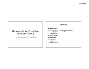
Figure 4.1: The simulation environment for a Verilog program (DUT) and testbench
20
CHAPTER 4: Verilog Simulation ‘timescale 1ns / 100ps module test; wire Cout; reg Cin; wire [1:0] Sum; reg [1:0] A; reg [1:0] B; twoBitAdd top(Cout, Sum, A, B, Cin); ‘include "testfixture.verilog" endmodule
Figure 4.2: Verilog code for a DUT/testbench simulation environment
c (Copyright 2005, 2010, Cadence Design Systems, Inc. All rights reserved worldwide. Reprinted with permission.)
Figure 4.3: Dialog box for initializing a simulation run directory
21
c (Copyright 2005, 2010, Cadence Design Systems, Inc. All rights reserved worldwide. Reprinted with permission.)
Figure 4.4: The initial Verilog-XL simulation control window
22
CHAPTER 4: Verilog Simulation
c (Copyright 2005, 2010, Cadence Design Systems, Inc. All rights reserved worldwide. Reprinted with permission.)
Figure 4.5: The Record Signals dialog box
c (Copyright 2005, 2010, Cadence Design Systems, Inc. All rights reserved worldwide. Reprinted with permission.)
Figure 4.6: Dialog to create a new testfixture template
23
c (Copyright 2005, 2010, Cadence Design Systems, Inc. All rights reserved worldwide. Reprinted with permission.)
Figure 4.7: The Verilog-XL Stimulus Options form
24
CHAPTER 4: Verilog Simulation
Figure 4.8: Testfixture template for the two-bit adder
25
Figure 4.9: An example testfixture for the two-bit adder
26
CHAPTER 4: Verilog Simulation // Default Verilog stimulus. integer i,j,k; initial begin A[1:0] = 2’b00; B[1:0] = 2’b00; Cin = 1’b0; $display("Starting simulation..."); for(i=0;i run Saw4 simulation is finished... If there were no ’ERROR’ statements, then everything worked! Simulation complete via $finish(1) at time 13200 NS + 0 ./testfixture.v:17 $finish; ncsim> exit --->
Figure 4.40: Output of stand-alone NC Verilog simulation of seetest.v
52
CHAPTER 4: Verilog Simulation
c (Copyright 2005, 2010, Cadence Design Systems, Inc. All rights reserved worldwide. Reprinted with permission.)
Figure 4.41: Control console for NC Verilog through SimVision
53 ---> sim-vcs -f test.files Chronologic VCS (TM) Version X-2005.06-SP2 -- Sat Jul 29 21:49:35 2006 Copyright (c) 1991-2005 by Synopsys Inc. ALL RIGHTS RESERVED This program is proprietary and confidential information of Synopsys Inc. and may be used and disclosed only as authorized in a license agreement controlling such use and disclosure. Parsing design file ’see4.v’ Parsing design file ’seetest.v’ Parsing included file ’testfixture.v’. Back to file ’seetest.v’. Top Level Modules: test No TimeScale specified Starting vcs inline pass... 1 module and 0 UDP read. recompiling module test make: Warning: File ‘filelist’ has modification time 41 s in the future if [ -x ../simv ]; then chmod -x ../simv; fi g++ -o ../simv -melf_i386 -m32 5NrI_d.o 5NrIB_d.o gzYz_1_d.o SIM_l.o /uusoc/facility/cad_tools/Synopsys/vcs/suse9/lib/libvirsim.a /uusoc/facility/cad_tools/Synopsys/vcs/suse9/lib/libvcsnew.so /uusoc/facility/cad_tools/Synopsys/vcs/suse9/lib/ctype-stubs_32.a -ldl -lc -lm -ldl /usr/lib64/gcc/x86_64-suse-linux/4.0.2/../../../../x86_64-suse-linux/bin/ld: warning: libstdc++.so.5, needed by /uusoc/facility/cad_tools/Synopsys/vcs/suse9/lib/libvcsnew.so, may conflict with libstdc++.so.6 ../simv up to date make: warning: Clock skew detected. Your build may be incomplete. CPU time: .104 seconds to compile + .384 seconds to link --->
Figure 4.42: Output of running sim-vcs on files.txt
54
CHAPTER 4: Verilog Simulation ---> sim-simv simv Chronologic VCS simulator copyright 1991-2005 Contains Synopsys proprietary information. Compiler version X-2005.06-SP2; Runtime version X-2005.06-SP2; 21:49 2006
Jul 29
Saw4 simulation is finished... If there were no ’ERROR’ statements, then everything worked! $finish at simulation time 13200 V C S S i m u l a t i o n R e p o r t Time: 13200 CPU Time: 0.090 seconds; Data structure size: Sat Jul 29 21:49:54 2006 --->
0.0Mb
Figure 4.43: Output of stand-alone VCS simulation of seetest.v using the compiled simv simulator
55
c (Reprinted by permission of Synopsys, Inc. Copyright 2005, 2010 Synopsys, Inc. All Rights Reserved)
Figure 4.44: Console window for controlling a VCS simulation through DVE
56
CHAPTER 4: Verilog Simulation
c (Reprinted by permission of Synopsys, Inc. Copyright 2005, 2010 Synopsys, Inc. All Rights Reserved)
Figure 4.45: The result of running the see4 simulation in DVE
57
c (Reprinted by permission of Synopsys, Inc. Copyright 2005, 2010 Synopsys, Inc. All Rights Reserved)
Figure 4.46: Waveform window for DVE after running the see4 simulation
58
CHAPTER 4: Verilog Simulation
c (Copyright 2005, 2010, Cadence Design Systems, Inc. All rights reserved worldwide. Reprinted with permission.)
Figure 4.47: A netlisting log for the two-bit adder that stops at behavioral views of the standard cell gates
c (Copyright 2005, 2010, Cadence Design Systems, Inc. All rights reserved worldwide. Reprinted with permission.)
Figure 4.48: The Setup Netlist dialog from Verilog-XL
59
c (Copyright 2005, 2010, Cadence Design Systems, Inc. All rights reserved worldwide. Reprinted with permission.)
Figure 4.49: The Setup Netlist dialog from NC Verilog
60
CHAPTER 4: Verilog Simulation
c (Copyright 2005, 2010, Cadence Design Systems, Inc. All rights reserved worldwide. Reprinted with permission.)
Figure 4.50: Netlisting result after removing behavioral from the verilogSimViewList
module NAND (out, in1, in2); output out; input in1, in2; assign #10 out = ˜(in1 & in2); endmodule
Figure 4.51: Verilog description of a NAND gate with explicit timing
module NAND (out, in1, in2); output out; reg out; input in1, in2; always @(in1 or in2) begin #10 out = ˜(in1 & in2); end endmodule
Figure 4.52: Another description of a NAND gate with explicit timing
61 module NAND (out, in1, in2); output out; reg out; input in1, in2; parameter delay = 10; always @(in1 or in2) begin #delay out = ˜(in1 & in2); end endmodule
Figure 4.53: NAND description with a delay parameter
module nand2 (Y, A, B); output Y; input A; input B; nand _i0 (Y, A, B); specify (A => Y) = (1.5, 1.0); (B => Y) = (1.7, 1.2); endspecify endmodule
Figure 4.54: NAND gate description with specify block
62
CHAPTER 4: Verilog Simulation
c (Copyright 2005, 2010, Cadence Design Systems, Inc. All rights reserved worldwide. Reprinted with permission.)
Figure 4.55: Rename Reference Library dialog box from Library Manager
c (Copyright 2005, 2010, Cadence Design Systems, Inc. All rights reserved worldwide. Reprinted with permission.)
Figure 4.56: Netlist log for the nand2 cell
63
c (Copyright 2005, 2010, Cadence Design Systems, Inc. All rights reserved worldwide. Reprinted with permission.)
Figure 4.57: Waveform from simulation of nand2 cell
c (Copyright 2005, 2010, Cadence Design Systems, Inc. All rights reserved worldwide. Reprinted with permission.)
Figure 4.58: Adding a property to a net
64
CHAPTER 4: Verilog Simulation
c (Copyright 2005, 2010, Cadence Design Systems, Inc. All rights reserved worldwide. Reprinted with permission.)
Figure 4.59: A net with a netType property
65
c (Copyright 2005, 2010, Cadence Design Systems, Inc. All rights reserved worldwide. Reprinted with permission.)
Figure 4.60: Nand2 cell with r nmos and trireg modifications
c (Copyright 2005, 2010, Cadence Design Systems, Inc. All rights reserved worldwide. Reprinted with permission.)
Figure 4.61: Waveform from simulation of nand2 cell with modifications
66
CHAPTER 4: Verilog Simulation