ASSEMBLY INSTRUCTIONS Also for use in assembly of JR Ergo Quattro when combined with Ergo Quattro Suppliment Instructions.
ERGO Z230 SPECIFICATIONS Overall Length
55.85"
Tail Rotor Diameter
10.34"
Overall Height
18.92"
Gear Ratio
6.77:1:5.18
Main Rotor Diameter
60.45"
Gross Weight
12.4 lbs.
Heli Division
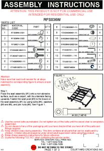
INTRODUCTION PRE-ASSEMBLY INFORMATION
Congratulations on your purchase of the JR Ergo helicopter kit. This kit has been both engineered and manufactured by JR with help from some of Japan’s top R/C helicopter engineers (now employed by JR).
Since this manual has been formatted for use in assembly of both the Ergo Z230 and the Ergo Quattro, near each assembly step number you will notice the following symbols:
As you may well know, the name JR has for years been synonymous with stateof-the-art, high quality radio control systems known the world over for their exceptional reliability and engineering. JR now brings this reputation and knowledge into the helicopter market with the development of the Ergo and the organization of the JR heli division. Years in the making, the Ergo’s superior quality and exceptional parts fit and finish create a new standard of quality that was previously unavailable. Before you begin the assembly of your Ergo, we suggest that you first review the entire instruction manual to become familiar with the assembly sequences and parts layout.
Z
For use in assembly of Ergo Z230 only
Q
For use in assembly of Ergo Quattro only
Z,Q
For use in assembly of both Ergo Z230 and Ergo Quattro
Please refer to these symbols to guide you in the specific assembly of your particular model.
WARNING The radio controlled model helicopter contained in this kit is not a toy, but a sophisticated piece of equipment. This product is not recommended for use by children. Radio controlled models such as this are capable of causing both property damage and/or bodily harm to both the operator/assembler and/or spectator if not properly assembled and operated. Horizon Hobby Distributors assumes no liability for damage that could occur from the assembly and/or use/misuse of this product.
When first opening your Ergo kit, you will notice that all of the parts are packaged and numbered to coordinate with the assembly step numbers of this instruction manual. All small hardware (nuts, bolts, washers, etc.) for each step are separated and packaged separately within the main parts bags. When beginning a section, you will need to open only the bag with the corresponding number to the section you are going to start. It is suggested that you place all of the hardware in an open container (e.g., coffee can) during assembly so as not to lose any of the small parts. It may also be helpful to familiarize yourself with the various sizes of screws, bolts, nuts, etc., as illustrated in the appropriate assembly section before you begin assembly. At the end of each assembly, in most cases, there should be no parts remaining.
AMA INFORMATION We strongly encourage all prospective and current R/C aircraft pilots to join the Academy of Model Aeronautics. The AMA is a non-profit organization which provides services to model aircraft pilots. As an AMA member, you will receive a monthly magazine entitled Model Aviation, as well as a liability insurance plan to cover against possible accident or injury. All AMA charter aircraft clubs require individuals to hold a current AMA sporting license prior to operation of their models. For further information, you can contact the AMA at: Academy of Model Aeronautics 5151 East Memorial Drive Muncie, IN 47302 (317) 287-1256
Great care has been taken in filling the bags with the correct quantity of parts and hardware for each section. However, occasionally mistakes do happen. In the event that you find a parts shortage or are in need of technical assistance, please contact your local JR heli division parts dealer, or contact the Horizon Service Center directly.
Horizon Service Center 4105 Fieldstone Road Champaign, IL 61821 (217) 355-9511 (9am to 5pm CST)
2
INDEX Section
Description
Page
Section
Description
Building Supplies . . . . . . . . . . . . . . . . . . . . . . . . . . . . . . . . . . . . . . . . .5
5-4
Tail Blade Holder Assembly . . . . . . . . . . . . . . . . . . . . . . .29
Tools/Field Equipment . . . . . . . . . . . . . . . . . . . . . . . . . . . . . . . . . . . . .6
5-5
Tail Pitch Control Lever Installation . . . . . . . . . . . . . . . .30
Hardware Identification . . . . . . . . . . . . . . . . . . . . . . . . . . . . . . . . . . . .7
5-6
Tail Boom Carrier Installation . . . . . . . . . . . . . . . . . . . . .30
1-1
Clutch Bell/Start Shaft Assembly . . . . . . . . . . . . . . . . . . . .8
5-7
Tail Boom Assembly Installation . . . . . . . . . . . . . . . . . . .31
1-2
Tail Drive Pinion/Bearing Block Assembly . . . . . . . . . . . .8
5-8
Vertical Fin Attachment . . . . . . . . . . . . . . . . . . . . . . . . . .31
1-3
Control Ball Installation . . . . . . . . . . . . . . . . . . . . . . . . . . .9
5-9
Tail Boom Brace Assembly . . . . . . . . . . . . . . . . . . . . . . .32
1-4
Servo Mixing Lever Unit Assembly . . . . . . . . . . . . . . . . .9
5-10
Tail Boom Brace/Horizontal Fin Installation . . . . . . . . . .32
1-5
Elevator Arm Assembly . . . . . . . . . . . . . . . . . . . . . . . . . .10
6-1
Upper Servo Tray Installation . . . . . . . . . . . . . . . . . . . . . .33
1-6
Fuel Tank Assembly . . . . . . . . . . . . . . . . . . . . . . . . . . . . .11
6-2
Servo/Switch Harness Installation . . . . . . . . . . . . . . . . . .34
2-1
Upper Main Frame Section Assembly . . . . . . . . . . . . . . .12
6-3
Tail Control Rod Assembly . . . . . . . . . . . . . . . . . . . . . . .35
2-2
Upper Main Frame Control Lever Installation . . . . . . . . .13
6-4
Tail Control Rod Installation . . . . . . . . . . . . . . . . . . . . . .35
2-3
Lower Main Frame Assembly . . . . . . . . . . . . . . . . . . . . .14
6-5
Gyro/Receiver/Battery Installation . . . . . . . . . . . . . . . . . .36
2-4
Fuel Tank Installation . . . . . . . . . . . . . . . . . . . . . . . . . . . .14
Radio System Preparation . . . . . . . . . . . . . . . . . . . . . . . . . . . . . . . . . .37
2-5
Front Radio Bed Installation . . . . . . . . . . . . . . . . . . . . . . .15
7-1
Aileron Linkages . . . . . . . . . . . . . . . . . . . . . . . . . . . . . . .38
2-6
Cooling Fan Shroud Installation . . . . . . . . . . . . . . . . . . . .15
7-2
Elevator Linkage Installation . . . . . . . . . . . . . . . . . . . . . .38
2-7
Upper/Lower Main Frame Assembly Attachment . . . . . .16
7-3
Collective Pitch Linkages . . . . . . . . . . . . . . . . . . . . . . . . .39
3-1
Main Drive Gear/Autorotation Assembly . . . . . . . . . . . . .17
7-4
Tail Control Rod Servo Connection . . . . . . . . . . . . . . . . .39
3-2
Main Drive Gear/Autorotation Assembly Installation . . .17
7-5
Throttle Linkage Installation . . . . . . . . . . . . . . . . . . . . . .40
3-3
Landing Gear Assembly Installation . . . . . . . . . . . . . . . .18
7-6
Control Lever/Linkage Adjustment . . . . . . . . . . . . . . . . .41
3-4
Engine Preparation/Cooling Fan Installation . . . . . . . . . .18
8-1
Body Assembly/Canopy Attachment . . . . . . . . . . . . . . . .42
3-5
Clutch Assembly Attachment . . . . . . . . . . . . . . . . . . . . . .19
8-2
Body Attachment . . . . . . . . . . . . . . . . . . . . . . . . . . . . . . .42
3-6
Engine Installation . . . . . . . . . . . . . . . . . . . . . . . . . . . . . .19
Decal Placement . . . . . . . . . . . . . . . . . . . . . . . . . . . . . . . . . . . . . . . . .43
3-7
Muffler Installation . . . . . . . . . . . . . . . . . . . . . . . . . . . . . .20
8-3
Main Rotor Blade Assembly . . . . . . . . . . . . . . . . . . . . . . .44
3-8
Carburator/Aircleaner Assembly Installation . . . . . . . . . .20
8-4
Main Rotor Blade Final Balancing . . . . . . . . . . . . . . . . . .45
4-1
Rotor Head Hub Assembly . . . . . . . . . . . . . . . . . . . . . . . .21
8-5
Main Rotor Blade Final Attachment . . . . . . . . . . . . . . . . .45
4-2
Main Blade Holder Assembly . . . . . . . . . . . . . . . . . . . . . .21
Final Servo Adjustment and Radio Set Up . . . . . . . . . . . . . . . . . .46-47
4-3
Main Blade Holder/Seesaw Attachment . . . . . . . . . . . . . .22
Data Sheets . . . . . . . . . . . . . . . . . . . . . . . . . . . . . . . . . . . . . . . . . .48-51
4-4
Seesaw Mixing Arm Installation . . . . . . . . . . . . . . . . . . .22
Final Pre-Flight Check . . . . . . . . . . . . . . . . . . . . . . . . . . . . . . . . . . . .52
4-5
Washout Unit Assembly . . . . . . . . . . . . . . . . . . . . . . . . . .23
Range Test/Initial Engine Start-Up & Adjustment . . . . . . . . . . . .53-54
4-6
Tail Pitch Slide Ring Assembly . . . . . . . . . . . . . . . . . . . .23
General Maintenance . . . . . . . . . . . . . . . . . . . . . . . . . . . . . . . . . . . . .55
4-7
Swashplate/Washout Assembly Installation . . . . . . . . . . .24
Rotor Head/Swashplate/Washout Assembly Parts List . . . . . . . . .56-57
4-8
Rotor head Installation . . . . . . . . . . . . . . . . . . . . . . . . . . .25
Cyclic Mixing Arms/Elevator/Aileron Control Arms Parts List . .58-59
4-9
Flybar Installation . . . . . . . . . . . . . . . . . . . . . . . . . . . . . . .26
Start Shaft/Clutch/Engine Assembly Parts List . . . . . . . . . . . . . . .60-61
4-10
Flybar Paddle Attachment . . . . . . . . . . . . . . . . . . . . . . . .26
Upper Main Frame/Radio Tray/Body Set Parts List . . . . . . . . . . .62-63
4-11
Rotor Head/Swashplate Control Rod Installation . . . . . . .27
Lower Main Frame/Landing Gear/Fuel Tank Parts List . . . . . . . .64-65
5-1
Tail Output Shaft/Pulley Assembly . . . . . . . . . . . . . . . . .28
Tail Boom/Tail Brace/Tail Boom Carrier Parts List . . . . . . . . . . .66-67
5-2
Tail Gear Case Assembly . . . . . . . . . . . . . . . . . . . . . . . . .28
Tail Case/Tail Blade Holders/Tail Pitch Plate Parts List . . . . . . . .68-69
5-3
Tail Center Hub Assembly . . . . . . . . . . . . . . . . . . . . . . . .29
Zenoah G23 Engine Service/Information Parts . . . . . . . . . . . . . . . . .70
3
Page
ERGO Z230 FEATURES Heavy-Duty Aluminum Quad Frame System Provides excellent rigidity and vibration absorption.
Self-Aligning One-Piece Steel Clutch System Offers easy installation and adjustment with exceptional reliability.
Powerful Zenoah G23 Gas Engine w/Recoil Start Provides reliable, economical gasoline operation. Convienent recoil starter included.
Straight Blade Axle Rotor Head Design Provides high responsiveness and solid blade tracking. Low Drag Flybar Paddles Provide quick yet smooth cyclic response at all flight speeds.
Wide Spread Tail Output Shaft Bearings Reduces vibration and improves control response.
Heavy-Duty Main Blade Grips with 4mm Blade Bolts Provide a solid and secure mounting surface to easily handle the stresses of radical flight.
Belt-Driven Tail Rotor Design Provides easy adjustment and low maintenance. Also eliminates the need for optional/expensive tube drive shafts.
Heavy-Duty Tail Boom Carrier Provides increased structural rigidity and improved tail rotor precision.
Precision Ball Bearings at All Critical Locations Provide low wear, high precision and reduced maintenance.
Superior Parts Fit and Finish Make assembly trouble free and enjoyable.
Unique Cyclic Mixing Control System Offers easy adjustment and precise control.
ITEMS REQUIRED TO COMPLETE THE JR ERGO (not supplied in kit) 1. RADIO SYSTEM REQUIREMENTS (NOT INCLUDED): 6-channel or greater PCM R/C helicopter system with 5 servos, 1000 mAh receiver battery and gyro.
Note: Due to the additional RF interference generated by the Zenoah G23 gasoline engine, it is highly recommended that only a PCM (Pulse Code Modulation) system be used with the Ergo Z230.
JRXP783 PCM
JRXP8103 PCM
Flight Pack
JRPCM10SX PCM
Gyro
4
PCM Receiver
2. BUILDING SUPPLIES (NOT INCLUDED): The following items are needed to complete the assembly of the JR Ergo Z230:
Gasoline Fuel Tubing (AER1073)
Gasoline Fuel Filter (DUB341)
Locktite 242 (Blue) Locktite (Red)
Double Sided Servo Mounting Tape
Nylon Wire Ties (to secure radio wires, etc)
Whip Antenna (RVO1010)
Dubro Brass Sintered Fuel Filters (2pc) (DUB161)
5 Minute Epoxy or Rotor Blade CA Adhesive
5
3. TOOLS NEEDED TO ASSEMBLE THE JR ERGO Z230 (NOT INCLUDED):
Hobby Knife
Small Hammer
Drill and Drill Bits
Sandpaper (80-100 Grit)
Needle Nose Pliers
Nut Drivers: 5mm, 7mm
Phillips Screwdriver
Allen Wrenches: 1.5, 2.0, 2.5, 3.0, 4.0mm
Blade Balancer
Scissors
Metric Ruler
Adjustable Pliers
4. FIELD EQUIPMENT REQUIRED (NOT INCLUDED):
DOT Approved Gasoline Can (93 octane unleaded gasoline recommended w/2 cycle oil added)
Pitch Gauge
2 Cycle Oil Additive (21 to 25% mix ratios)
Gasoline Fuel Pump
Ball Link Pliers
6
Fire Extinguisher
Training Gear (Beginners Only)
HARDWARE IDENTIFICATION There are a variety of sizes and shapes of hardware included in this kit. Prior to assembly, please be careful to identify each screw by matching it to the full size screw outlines included in each step.
C
A
C
A
B
Self Tapping Screw
3mm
Flat Washer
B
2.6x10mm
A
A
Socket Head Bolt
B
B
C
Socket Head Bolt
A
B
C Set Screw
A
2x8mm
A
B
Flat Head Screw
3mm
Lock Nut
B
C
Set Screw
B
Flat Head Screw
A
B
A B
3mm
Star Washer
3x8mm
C Flat Head Cap Screw A
A
B
C
Star Washer
A
B
2mm
Hex Nut
Flat Head Cap Screw
A
B
B
Flat Washer
C
B
B
C
B
Self Tapping Screw
A
4x4mm
.05mm
A
C
A
B
3x8mm
A
A
All of the hardware, screws, nuts, etc., contained in the Ergo kit are described in the following A, B, C manner:
Hex Nut
7
Lock Nut
1-1
CLUTCH BELL/START SHAFT ASSEMBLY
Z,Q
Starter Hex Adaptor 4x4mm Set Screw (Use Threadlock)
Use Threadlock
..........1 pc
Complete Assembly
Start Shaft Bearing Block
4x4mm Set Screw Note: These items are pre-assembled
Be sure that the Bearing with the 5mm ID faces upward
Pinion Gear (13T) (Use Threadlock when assembling)
Start Shaft Clutch Bell Assembly
1-2 Z,Q *
TAIL DRIVE PINION/BEARING BLOCK ASSEMBLY UP Install the Upper Bearing Block so the bearing is toward the bottom
Bearing
RED Use Red Threadlock
*
...1 pc
RED
3mm Flat Washer
3x6mm Socket Head Bolt
.........1 pc
Front Tail Belt Pulley (Install Flat Side Up)
3mm Flat Washer
Note: It will be necessary to press the two Bearings into the Bearing Blocks. Press the Bearings in evenly by hand. Do not use a vise or pliers for this procedure as damage could result.
3x6mm Socket Head Bolt (Use Red Threadlock)
Tail Drive Pinion Bearing Blocks
Complete Assembly
Tail Drive Pinion with Shaft
UP Bearing
Install the Lower Bearing Block so the bearing face is toward the top
8
1-3 Use Threadlock
CONTROL BALL INSTALLATION 2x8mm Flat Head Screw (Use Threadlock)
Z,Q
3x5x1.8mm Spacer 2mm Nut
2mm Nut
5x8x4mm Ball Bearing
........1 pc 2x8mm Flat Head Screw
........8 pc 2x10mm Flat Head Screw
2x10mm Flat Head Screw
........9 pc Steel Joint Ball
........3 pc Steel Joint Ball
2mm Nut
........8pc 5x8x4mm Ball Bearing
3x5x3.8mm Spacer
........3pc 3x5x3.8mm Spacer
2x10mm Flat Head Screw
5x8x4mm Ball Bearing
.......1pc 3x5x1.8mm Spacer
Mixing Lever (3pc) (Prepare 3 Sets)
1-4
Steel Joint Ball
SERVO MIXING LEVER UNIT ASSEMBLY
Z,Q
Complete Assembly
Use Threadlock 3mm Lock Nut 3x4.5x.7mm (x4) Steel Washer
........2 pc
Mixing Lever Spacer
3x8mm Flat Head Screw
........1 pc 3x55mm Socket Head Bolt
3mm Lock Nut
....4 pc 3x4.5x.7mm Steel Washer
........1 pc Mixing Lever Spacer
Mixing Base Cross Member Mixing Base Arm (Roll)
Mixing Base Cross Member ....1 pc
3x55mm Socket Head Bolt
3x8mm (x2) Flat Head Screw (Use Threadlock)
........5 pc
9
1-5
ELEVATOR ARM ASSEMBLY
Z,Q ..........2 pc 2x8mm Flat Head Screw
.........2 pc
Elevator Arm Rear
Elevator Arm Front
Steel Joint Ball Elevator Arm Pin
Swashplate A Arms
.......2 pc
Steel Joint Ball Steel Joint Ball 2x8mm Flat Head Screw
2x8mm Flat Head Screw
Elevator Arm Pins
Caution: Be sure to note the correct installation direction of the Swashplate A Arm.
Marked Side In
Marked Side Out
Swashplate A Arm
Elevator Arm (Front)
Swashplate A Arm
Tap in gently with a small hammer.
Swashplate A Arm
Elevator Arm (Rear)
10
Edge of Work Bench
Elevator Arm
1-6
FUEL TANK ASSEMBLY
Z,Q Note: The Fuel Tank Fittings included in the Z230 kit are made specifically for gasoline use. 1. Cut the small Gasoline Tubing (included) to a length of 77mm. Next, connect the Fuel Tank Clunk, Nipple, and medium Gasoline Fuel Tubing (not included) as shown below.
77mm Fuel Tank Clunk
Nipple
Gasoline Fuel Tubing (Small) Gasoline Fuel Tubing (not included) Connects to Muffler Pressure Tap
Medium Gasoline Fuel Tubing (not included) Connects to Engine Carburetor
2. Insert the assembly above (Fuel Tank Clunk first) into the Fuel Tank opening so that the Nipple is inside the tank. Next, slide the Fuel tank Grommet over the medium Fuel Tubing.
4. Pull the medium Gasoline Fuel Tubing out of the Fuel Tank until the threads of the Fuel Tank Nipple are exposed.
Pull out until Nipple threads are exposed
Fuel Tank Grommet
3. Insert the Fuel Tank Grommet into the Fuel Tank opening, making sure that it is fully seated. Make sure Grommet is fully seated.
6. Completed Assembly
5. Remove the medium Gasoline Fuel Tubing from the Nipple and secure the Nipple to the Fuel Tank using the 7x12x1mm Washer and 7mm Nut supplied. Be sure to secure this assembly firmly to avoid leakage.
Use two Wrenches if necessary to secure Tank Nipple. 7mm Nut
11
7x12x1 Washer
2-1
UPPER MAIN FRAME SECTION ASSEMBLY
Z,Q ..........22 pc
Use Threadlock
3x8mm Socket Head Bolt
..........2 pc 3mm Lock Nut Tail Control Rod Guide
..........11 pc 3mm Flat Washer
..........2 pc
Body Mounting Standoff
*
Note: Due to the addition of the Frame Double Plates, only four 3mm Flat Washers are required for this step.
3x6mm Socket Head Bolt
..........1 pc
Body Mounting Standoff: Short
3x6mm Socket Head Bolt
Bearing side must face upward
..........4 pc 2.6x8mm Self Tapping Screw
Note: Be sure to use the two shorter Body Mount Standoff for this installation.
* *
* This hardware is packaged seperately with the two Frame Doubler Plates. 2.6x8mm Self Tapping Screws
*
*
* *3mm Lock Nut (2pc)
*
* *
*
* *
Bearing side must face downward
Servo Mounting Plates
Frame Double Plate (2pc)
3mm Flat Washer (11 pc)
3x8mm Socket Head Bolt (21 pc)
When installing the Main Rotor Shaft Bearing Blocks, it is important to note the correct direction in which they need to be installed. Please refer to the diagram below for clarification.
Lower Main Shaft Bearing Block
Upper Main Shaft Bearing Block UP
Bearing Flush with Flange Bearing
Position so the side of the bearing block that has the bearing flush with the flange is upward.
UP
Bearing Flush with Flange Bearing
12
Position so side of the bearing block that has the bearing flush with the flange is downward.
2-2
UPPER MAIN FRAME CONTROL LEVER INSTALLATION
Z,Q Nylon Washer Elevator Arm Bushing 3x8mm Socket Head Bolt
Use Threadlock
Elevator Arm Bushing Nylon Washer
3mm Lock Nut
Nylon Washer 3x6mm Socket Head Bolt
Note: Be sure to install the Elevator Arm Units in their proper location as there is a “Front” and a “Rear” Unit (Step 1-5).
3x8mm Socket Head Bolt (Use Threadlock)
Roll Bell Crank Spacer
3x22mm Socket Head Bolt Mixing Base Nut (2 pc) 3x6mm Socket 3x4.5x.4mm Steel Washer Head Bolt (Use Threadlock)
Roll Bell Crank
........2 pc 3x6mm Socket Head Bolt
........4 pc 3x8mm Socket Head Bolt
Assemble and attach the Control Rods to the Mixing Levers/Control Arms as shown:
3x22mm Socket Head Bolt
......1 pc
........1 pc 3mm Lock Nut
A
Note: When adjusting final control rod lengths, make sure that “JR Propo” moulded into the Ball Link faces outwards before attaching to the Steel Joint Balls.
B
........4 pc
C
Nylon Washers
........1 pc
Rod Length
........1 pc
Adjustment Length
3mm Flat Washer
Roll Bell Crank Spacer
Elevator Arm Bushing
........2 pc
Mixing Base Nut
........2 pc
A B C
13
Rod Length 120mm 55mm 90mm
Adjust Length To 104mm 36mm 72mm
2-3
LOWER MAIN FRAME ASSEMBLY
Z
ERGO Z230 ONLY
* Note: Make sure that the frames are positioned so that the counter sunk screw holes face towards the inside of the Main Frame Assembly as shown.
Use Threadlock
4x12mm Socket Head Bolt
3x8mm Sockethead Bolt (4pc)
ERGO Z230 ONLY
Lower Frame Angle (2pc) 4mm Nut
....1 pc 4x12mm Socket Head Bolt Lower Main Frame Halves
......1 pc 4mm Lock Nut
3x10mm (4pc) Flat Head Screw
....10 pc 3x8mm Socket Head Bolt
......8 pc 3mm Lock Nut
......4 pc 2.6x8mm Self Tapping Screw
......4 pc
2.6x8mm Self Tapping Screw Servo Installation Plate *Counter Sunk Holes 3x8mm Socket Head Bolt (Use Threadlock)
3x10mm Flat Head Screw
2-4
3mm Lock Nut (8pc)
FUEL TANK INSTALLATION
Z,Q Note: Install the Fuel Tank and Tank Mounting Rubber into the lower frame halves before attaching the Main Frame Standoffs. When securing Standoffs to Frame, position the bottom of the frame on a level surface to prevent twisting during tightening. Also be sure to use the correct length bolt in the correct location when assembling.
Assembled Fuel Tank
Tank Mounting Rubber 3x8mm Socket Head Bolt (2pc)
3mm Lock Nut (2pc)
Note: Select the correct Tank Mounting Rubber as follows: Ergo Z230: Grey (Soft) Ergo Quattro: Black (Hard)
Use Threadlock on all screws in this assembly.
......2 pc
Fuel Tank Holder (2pc)
3mm Lock Nut
......2 pc 3x8mm Socket Head Bolt
......4 pc 3x10mm Socket Head Bolt
Main Frame Standoff, 80mm
Main Frame Standoff (2pc)
...3 pc
3x10mm Socket Head Bolt (4pc)
14
Attach a small piece of double sided 1/8" servo tape (not included) to the inside of the two tank holders prior to installation.
2-5
FRONT RADIO BED/INSTALLATION
Z,Q Front Radio Bed
* Install the Front Radio Bed Spacer in the correct direction as shown.
Use Threadlock
*Front Radio Bed Spacers (2pc)
Shorter Distance
UP Front Radio Bed Spacer 3x18mm Socket Head Bolt (2pc)
Install the 3x25mm Set Screw into the Body Mounting Standoffs to the correct distance as shown and secure with Threadlock.
3x18mm Socket Head Bolt
.....2 pc
3x25mm Set Screw
.....2 pc
Body Mounting Standoff, 29mm
2-6
Body Mounting Standoff, 29mm (2pc)
3x25mm Set Screw (2pc)
.....2 pc
COOLING FAN SHROUD INSTALLATION
Z,Q Cooling Fan Shroud
......4 pc 3x8mm Self Tapping Screw
3x8mm Self Tapping Screw (4pc)
Remove
Before installation, remove the shaded areas of the Fan Shroud as shown above. The exact trimming outlines are moulded into the inside portion of the cooling fan shroud for convienience.
15
2-7
UPPER/LOWER MAIN FRAME ASSEMBLY ATTACHMENT
Z,Q Use Threadlock on all screws in this assembly.
......14 pc 3x22mm Socket Head Bolt
.....7 pc Main Frame Standoff, 32mm Main Frame Spacer, 22mm (14pc)
......14 pc Main Frame Spacer, 22mm
Main Frame Standoff, 32mm (7pc)
3x22mm Socket Head Bolt (14pc)
16
3-1
MAIN DRIVE GEAR/AUTOROTATION ASSEMBLY
Z,Q
3x6mm Socket Head Bolt (4 pc) Tighten equally to prevent warping of Main Drive Gear
Use Threadlock
Main Drive Gear
.......4 pc 3x6mm Socket Head Bolt
Autorotation Assembly
3-2
MAIN DRIVE GEAR/AUTOROTATION ASSEMBLY INSTALLATION Main Shaft Collar
Z,Q
4x4mm Set Screw (4 pc)
14mm Use Threadlock on all screws in this assembly
Main Rotor Shaft
.......8 pc 4x4 Set Screw 3mm
When assembling, be sure that two of the four 4mm Set Screws engage into the through hole in the bottom of the Main Rotor Shaft.
1. Secure the Autorotation Hub to the Main Rotor Shaft using four 4x4mm Set Screws. Next, slide the Main Shaft Collar onto the Main Rotor Shaft. While pulling upward on the Main Rotor Shaft, secure the Main Shaft Collar to the Main Rotor Shaft using the remaining four 4x4mm Set Screws.
4x4mm Set Screws (4pc)
2. Once the Main Shaft Assembly is in place, adjust the gear mesh of the Clutch Bell and Tail Belt Pinion Gears, and secure the bolts left loose from Step 2-1.
17
3-3
LANDING GEAR ASSEMBLY INSTALLATION
Z,Q
3x8mm Socket Head Bolt (4 pc)
Use Threadlock
......4 pc 4x4mm Set Screw
3x8mm Socket Head Bolt
......4 pc ......4 pc Landing Gear Dampers (4 pc)
3x12mm Socket Head Bolt
4x4mm Set Screws (4 pc)
......4 pc 3mm Washer 3mm Washer (4 pc) 3x12mm Socket Head Bolt (4 pc)
* Use CA Adhesive to attach Landing Skid Caps to Skid Tubes
*Landing Skid Cap Landing Skid
3-4 Z Air Cleaner Assembly
ENGINE PREPARATION/COOLING FAN INSTALLATION At this time, please remove the Aircleaner Assembly, Carburator, Carburator Insulator Plate, and Coil Assembly as shown below: Carburator
6x18mm Socket Head Bolt
Carburator Insulator Plate Zenoah G23 Engine
Aluminum Cooling Fan Assembly Use Threadlock Coil Assembly
......1 pc 6x18mm Socket Head Bolt
18
3-5
CLUTCH ASSEMBLY ATTACHMENT
Z Clutch Assembly Apply a light coating of oil or grease to the bearing before installation.
Use Threadlock
......2pc 4x6mm Socket Head Bolt
4x6mm Socket Head Bolt (2pc)
3-6
ENGINE INSTALLATION
Z
3mm Lock Nut (4pc)
......4pc 3x15mm Socket Head Bolt
......4pc 3mm Lock Nut
4x30mm Socket Head Bolt
......2pc ......2pc
4mm Lock Nut
3mm Washer
4mm Lock Nut (2pc)
......4pc
......2pc 4mm Washer
Make sure that the Coil Sheild Grounding Wire makes contact with the exposed brass plate moulded into the Coil Mounting Tab.
Coil Mounting Spacers Coil Shield Coil Assembly
......2pc 4x8x14mm Coil Mounting Spacers Coil Grounding Wire
4x30mm Socket Head Bolt 4mm Washer (2pc)
Black Coil Wire (Ignition kill not required)
3mm Washer (4pc)
......2pc ......1pc
3x8mm Socket Head Bolt
Coil Grounding Wire
INCORRECT INCORRECT CORRECT Adjust the position of the Engine and Clutch Assembly as shown so the bottom of the Clutch Assembly is flush with the bottom of the Clutch Bell. Also check to insure that the Engine and Clutch Bell are parallel.
19
3x15mm Socket Head Bolt (4pc) Red Coil Wire (Connect to Red Coil Wire from engine after installation)
Red Coil Wire (Connect to Red Wire from Coil after engine is installed)
3-7
MUFFLER INSTALLATION
Z
Secure the Muffler Tab to the 4x12mm Socket Head Bolt as shown below. 4mm Washer (2pc) 4mm Lock Nut
4x12mm Socket Head Bolt (Installed in Step 2-3)
Use Threadlock Muffler
Muffler Tab 4mm Washer (2pc)
......1pc 4mm Lock Nut
4x12mm Socket Head Bolt
.....4 pc 4mm Washer
...2 pc Muffler Gasket (2pc)
4x12mm Socket Head Bolt
Muffler Spacer Muffler
.....2pc
5x60mm Socket Head Bolt
5x60mm Socket Head Bolt (2pc)
3-8
CARBURATOR/AIR CLEANER ASSEMBLY INSTALLATION
Z
Attach the Carburator Overflow Vent Line and the Fuel Tank Vent Line to each side of the Mainframe as shown at right. Make sure that the Sintered Filters are below the frame.
* Carburator Duplicate on other side of Overflow Vent: Heli for Fuel Tank Vent Nylon Wire Tie (2pc) (not included)
Use Threadlock Fuel Tank Vent (7" Long)
Fuel Line (6" Long) Connect to Fuel Inlet Nipple as shown.
Insulator Plate Gasket Carburator Insulator Plate
5x20mm Carburator Insulator Plate Bolt (2pc)
Carburator Overflow Vent (9" Long)
Dubro Sintered Bronze Filter (2pc) (not included)
Carburator Gasket
Note: It is suggested that an In Line Fuel Filler be installed into the Main Fuel Line (not included).
.....1pc 2x8mm Flat Head Screw
.....1pc
Steel Joint Ball
Air Filter
3x3mm Set Screw
Steel Joint Ball
.....1pc 2mm Nut
2x8mm Flat Head Screw
Carburator Assembly
.....1pc
Air Cleaner Cover
3x3mm Set Screw
.....2pc Included 5x20mm Carburator Insulator Plate Bolt with Engine 5x55mm Air Cleaner Mounting Bolts
.....2pc
5x55mm Air Cleaner Air Cleaner Mounting Bolts (2pc) Body
2mm Nut * Throttle Arm
20
*Install the Throttle Arm so that when the Carburator is at 1/2 throttle, the Throttle Arm is exactly 90° to the Carburator Flange as shown above use Threadlock
4-1
ROTOR HEAD HUB ASSEMBLY
Z,Q Head Button
Use Threadlock
..... 5 pc 3x8mm Socket Head Bolt Main Rotor Head Body 3x8mm Socket Head Bolt Main Rotor Hub
3x8mm Socket Head Bolt (5 pc)
Phase Adjustment Ring (insert onto base of Main Rotor Hub)
4-2
MAIN BLADE HOLDER ASSEMBLY
Z,Q TWO SETS REQUIRED
......2 pc
Main Blade Holder Bearing
4.5mm Control Ball Main Blade Holder
......4 pc
Control Ball 4.5mm (Pre-Installed)
Main Blade Holder Bearing
Note: Use caution when inserting the Main Blade Holder Bearings so as not to distort/damage the Main Blade Holders.
Main Blade Holder Bearing
21
4-3
MAIN BLADE HOLDER/SEESAW ATTACHMENT
TWO SETS REQUIRED Use Threadlock
...2 pc *As Dampner Rubbers
5x10mm Socket Head Bolt
will wear during use, check regularly and replace when necessary.
Z,Q
*Note: There are two different style Dampner Rubbers included in this kit. The recessed, or hollow type is a 20 rating (soft). The solid version is a 40 rating (medium) and is suggested for use with this kit. (In some kits, the solid type (40 rating) Dampner Set may be included in the instruction manual package.) Blade Spindle Shaft * Dampner Rubber
....2 pc
Thrust Bearing
Silver Grip Spacer Thrust Bearing
......2 pc Spindle Washer (Black)
Seesaw Shaft
......2 pc Grip Spacer (Silver)
3x5mm Flat Head Hex Screw (2 pc)
Steel Seesaw Spacer (2 pc) Install into bearings from the inside prior to sliding the seesaw shaft into position.
12x16x0.5mm washer
Tighten securely using two 4mm “L” Allen Wrenches. 5x10mm Socket Head Bolt (Use Threadlock)
4-4
......2 pc
Large I.D.
......2 pc 12x16x0.5mm Washer
Caution: Be sure to note correct placement of Large/Small I.D. Thrust Washers during assembly.
Small I.D. (with line) Black Spindle Washer
3x5mm Flat Head Hex Screw
......2 pc Seesaw Spacer (Steel)
SEESAW MIXING ARM INSTALLATION
Z,Q Use Threadlock
...2 pc 3x15mm Socket Head Bolt 3x4.5x.7 Washer
*The Seesaw Mixing Arms included with this kit provide approximately 18° - 19° Total Pitch Travel. For increased Pitch Travel for 3D flight (23°), it is recommended that part #JRP960178 Seesaw Mixing Arms be used.
....2 pc
Note: The four 2x8mm Flat Head Screws and Steel Joint Balls are pre-installed onto the Seesaw Mixing Arms.
3x4.5x.7 Washer (2pc) *2x8mm Flat Head Screw (4pc) *Seesaw Mixing Arms (2pc) *Steel Joint Ball (4pc) 3x15mm Socket Head Bolt (2pc)
22
4-5
WASHOUT UNIT ASSEMBLY
Z,Q TWO SETS REQUIRED
....2 pc
3x.05x1.8mm Spacer (2pc)
3x15mm Socket Head Bolt 5x8x4mm Ball Bearing (4pc)
....2 pc 2x10mm Flat Head Screw
....4 pc 5x8x4mm Ball Bearing
Washout Base
3x4.5x4mm Washer
3x15mm Socket Head Bolt (2pc)
....2 pc Washout Link Pin Washout Arm
....4 pc
2x10mm Flat Head Screw (2pc)
Pin Stopper Ring, 2mm
3x4.5x.4mm Washer
Steel Joint Ball
3x.05x1.8mm Spacer
....4 pc ....2 pc
Slide Washout Link Pin in at center. Next, press the two Pin Stopper Rings into place Pin Stopper Ring (4pc)
....2 pc
4-6
Steel Joint Ball (2pc)
Washout Link Pin (2pc) Washout Link Pin
TAIL PITCH SLIDE RING ASSEMBLY
Z,Q Tail Pitch Link Pin Be sure to center Pin between Pitch Link Ears when installing.
....2 pc Tail Pitch Link Pin
Note: Tail Pitch Slide Ring Sleeve is reverse (left hand) thread. Use caution when installing.
Tail Pitch Link Tail Pitch Plate
(Installing with four moulded circle marks in link facing upward)
Tail Pitch Link Pin
Tail Slide Ring Collar w/Bearing Tighten
Tail Pitch Slide Ring Sleeve
23
4-7
SWASHPLATE/WASHOUT ASSEMBLY INSTALLATION
Z,Q Washout Base
WASHOUT ASSEMBLY INSTALLATION
Washout Assembly Long Flange
UP
Install onto the Mainshaft so the longer portion of the Washout Base faces downward toward the Swashplate Swashplate Assembly
UPPER SWASHPLATE RING
TOP VIEW OF SWASHPLATE Connect the two Washout Links to the correct Upper Swashplate Balls as shown.
Complete Assembly
24
4-8
ROTOR HEAD INSTALLATION
Z,Q Completed Rotor Head Assembly
3mm Lock Nut
*
....1 pc 3x26mm Socket Head Bolt (Long Shank)
....1 pc 3mm Nut
3x26mm Socket Head Bolt
*Note: Be sure to use the special 3x22mm Long Shank Bolt (included in the separate screw bag)
Be sure to engage the Phase Adjusting Ring Pin into the Washout Base Groove before securing the Rotor Head Assembly in place.
When the Main Rotor Head is secured in place, make sure the Swashplate and Washout Assembly are aligned 90° to the helicopter. This procedure is important to insure correct control inputs. Adjust the Phase Adjusting Ring if necessary.
25
4-9
FLYBAR INSTALLATION
Z,Q
Flybar Control Arm (2 pc)
Use Threadlock
4mm Washer (2pc) 4x4mm Set Screw (2 pc)
....2 pc 4x4mm Set Screw
....2 pc Steel Joint Ball
....2 pc 2x8mm Flat Head Screw
....2 pc
Flybar
4mm Washer
Note: 2x8mm Flat Head Screw (2 pc)
Center the Flybar in the Seesaw Shaft before securing the two Flybar Control Arms
Steel Control Ball (2 pc) Flybar Control Arm (2 pc)
Attach the Steel Control Ball to the Flybar Control Arm (2) as shown.
4-10
Check to insure that the two Flybar Control Arms are parallel to the center line of the Flybar
FLYBAR PADDLE ATTACHMENT
Z,Q ....2 pc 4x4mm Set Screw
*Note: Slide the Flybar Weights onto the Flybar before installation of the Flybar Paddles. For increased cyclic response (3D Flight), Flybar Weights should be omited.
* Flybar Weight (2 pc)
Note proper direction of each Flybar Paddle (short portion forward, clockwise rotation)
....2 pc 4mm Nut 4x4mm Set Screw (2 pc)
m 6m Flybar Paddles
4mm Lock Nut (2 pc)
Thread each flybar paddle onto the Flybar until the threaded tip of the Flybar protrudes approximately 6mm. Adjust each Flybar Paddle so they are parallel to the Flybar Control Arms and to each other. Secure the Flybar Paddles using two 4mm Lock Nuts.
26
4-11
ROTOR HEAD/SWASHPLATE CONTROL ROD INSTALLATION
Z,Q 1 2
4
3
CONTROL ROD ASSEMBLY Thread the Universal Links onto the threaded Control Rods to the lengths shown below. Please note that all links should be adjusted so that when attached to the Control Ball, the words “JR Propo” are to the outside. 1
SEESAW ARM TO MAIN BLADE HOLDER
3
(2.3x15mm Threaded Rod)
SWASHPLATE TO ROLL BELLCRANK (2.3x30mm Threaded Rod)
x2
x1
Universal Link (Short) 5° main blade pitch at center stick (normal/beginner)
2
1mm
3mm
8mm
Universal Link
0° main blade pitch at center stick (3D Setup)
4
WASHOUT ARM TO FLYBAR CONTROL ARM
SWASHPLATE TO SEESAW ARM (2.3x40mm Threaded Rod)
x2
x2 Adjust so Links are 90° to each other.
Double Link (Long) (1 pc)
27
19mm
Universal Link
5-1
TAIL OUTPUT SHAFT/PULLEY ASSEMBLY
Z,Q Spring Pin
....1 pc
Adjustable Pliers
Spring Pin
Spring Pin
Tail Output Shaft
Press in Spring Pin gently using adjustable pliers. Be sure to center pin through the Tail Case Pulley when completed. Longer Distance
Press pin into this hole
Note correct direction of Tail Output Shaft during assembly
Tail Case Pulley
5-2
TAIL GEAR CASE ASSEMBLY
Z,Q
3x10mm Socket Head Bolt 3x10mm Socket Head Bolt
Use Threadlock
....3 pc 3x10mm Socket Head Bolt
....6 pc
Tail Gear Case (L/R) Tail Output Shaft Bearing
2.6mmx10mm Socket Head Bolt (6 pc) Tail Output Shaft Bearing
2.6x10mm Socket Head Bolt Tail Drive Belt
....6 pc 2.6mm Hex Nut
Tail Boom
....2 pc
m 80m
Tail Output Shaft Bearing
Wrap tape around the end of the Tail Drive Belt temporarily to ease insertion through the Tail Boom . Be careful not to “kink” the Tail Drive Belt.
Tail Drive Belt
2.6mm Hex Nut (6 pc)
Note: Be sure to position the Tail Gear Case onto the shorter slotted side of the Tail Boom. Longer (Helicopter)
28
Shorter (Tail Gear Case)
5-3
TAIL CENTER HUB ASSEMBLY ....2 pc
3x3mm Set Screw
Use Threadlock
Z,Q 3x3mm Set Screw (2 pc)
TWO SETS REQUIRED Tail Center Hub
....2 pc
3mm Lock Nut
Tail Blade Holder Bearing (Sealed) (2 pc)
Tail Slide Ring Assembly
Tail Thrust Bearing
....2 pc Tail Blade Holder Bearing (Sealed)
10x7mm Washer (Large) Large I.D.
....2 pc
Small I.D.
Tail Blade Holder Bearing (Open)
Caution: Be sure to note correct placement of Large/Small I.D. Thrust Washers during assembly
....2 pc Washer, 10x7mm (Large)
....2 pc Washer, 7x4mm (Small) 7x4mm Washer (Small) Tail Blade Holder Bearing (Open) (2 pc)
....2 pc
3mm Lock Nut
Tail Thrust Bearing
Slide the Tail Slide Ring Assembly on the Tail Output Shaft before installation of the Tail Rotor Hub. When attaching the Tail Rotor Hub, be certain that the two 3x3mm Set Screws engage into the holes at the end of the Tail Output.
5-4
3mm Lock Nut
When assembling, check to make sure the Tail Blade Holder Bearings can rotate freely, without play. If binding occurs, loosen the 3mm Lock Nut Slightly.
TAIL BLADE HOLDER ASSEMBLY
TWO SETS REQUIRED
....2 pc 2x10mm Flat Head Screw
Z,Q
....8 pc 2x8mm Socket Head Bolt
Tail Blade Holder w/Flange (Outside)
Steel Joint Ball
2x10mm Flat Head Screw
2x8mm Socket Head Bolt
....2 pc 3x15mm Socket Head Bolt
....8 pc
Connect the Tail Pitch Links to the Steel Control Balls after the Tail Blade Holders have been assembled.
2mm Hex Nut 3mm Lock Nut
....2 pc 3mm Lock Nut Leading Edge
....2 pc Steel Joint Ball
*Be sure to note the correct direction of the Tail Rotor Blades during assembly. Rotation Direction
2mm Hex Nut Tail *Tail Rotor Blade (2 pc)
29
3x15mm Socket Head Bolt
5-5
TAIL PITCH CONTROL LEVER INSTALLATION
Z,Q ........1 pc 2x8 Flat Head Screw
......1 pc 2x20mm Socket Head Bolt
........1 pc 2mm Flat Washer
........1 pc Steel Joint Ball
........1 pc Tail Lever Bushing
Snap Onto Ball
Tail Lever Bushing
5-6
Tail Pitch Control Lever
2mm Flat Washer
Steel Joint Ball
2x20mm Socket Head Bolt
2x8mm Flat Head Screw
TAIL BOOM CARRIER INSTALLATION
Z,Q 3mm Lock Nut
3mm Lock Nut
Tail Boom Carrier (L&R)
........4 pc 3x15mm Socket Head Bolt
..2 pc 3x40mm Socket Head Bolt
........6 pc 3mm Lock Nut
*3x15mm Socket Head Bolt
*3x40mm Socket Head Bolt
* Do not fully tighten at this time. These bolts will be secured in Step 5-7.
30
5-7
TAIL BOOM ASSEMBLY INSTALLATION
Z,Q Slide the Tail Boom through the Tail Boom Carrier and engage the Tail Drive Belt over the Front Pulley. Be certain to note the correct rotation (direction shown below). Set the belt tension per the directions below.
Secure Bolts completely after inserting Tail Boom, making sure the Tail Output Shaft is exactly 90° to the Main Rotor Shaft.
Note: It may be necessary to add one thickness of electrical tape around the end of the Tail Boom to insure positive attachment to the Tail Boom Carrier.
Tail Output Shaft Pulley
Belt tension should be set so when pressing with your finger, both sides of the belt do NOT come in contact with each other. Be sure not to set the belt too tight, as this can cause vibration and a loss of power.
Rotate the Tail Drive Belt in the direction shown before installing it onto the front pulley. It is extremely important to install the belt in the proper direction to insure correct rotation of the Tail Rotor Blades.
Front Pulley
5-8
VERTICAL FIN ATTACHMENT
Z,Q
Vertical Fin
........3 pc 3x12mm Tapping Screw
Tail Boom Stripe Decals
Attach decals as shown It is suggested that decals be applied to both the Tail Boom and the Vertical Fin at this time. Clean the surfaces with rubbing alcohol to remove oil, etc., before attaching decals.
31
3x12mm Self Tapping Screw (3 pc)
5-9
TAIL BOOM BRACE ASSEMBLY
Z,Q TWO SETS REQUIRED
........4 pc
2.6x12mm Socket Head Bolt
2.6x12 Socket Head Bolt Tail Brace Tube
It is suggested that the Tail Brace Connectors be bonded to the Tail Brace Tubes using either thick CA Adhesive or JB Weld.
2.6x12mm Socket Head Bolt
Tail Brace Connector (4 pc)
5-10
TAIL BOOM BRACE/HORIZONTAL FIN INSTALLATION
Z,Q
For easy installation, insert these two nuts into the Horizontal Fin/Brace Clamp first. 3mm Lock Nut (4 pc)
3x30mm Set Screw (Use Threadlock)
Use Threadlock
Horizontal Fin
It is suggested that decals be applied to the horizontal fin prior to assembly. Use rubbing alcohol to remove oil, etc., before attaching decals.
........2 pc 3x8mm Socket Head Bolt
........2 pc 3x10mm Socket Head Bolt
........2 pc 3x12mm Socket Head Bolt
........4 pc 3mm Washer
....1 pc 3x30mm Set Screw
Main Frame Standoff, 80mm
3x12mm Socket Head Bolt Parts Assembled in Step 5-9.
3x8mm Socket Head Bolt
3x10mm Socket Head Bolt (2pc) Dome Nut (2 pc)
........4 pc 3mm Lock Nut
........2 pc Dome Nut
Main Frame Standoff, 80mm
........1 pc
32
3mm Washer
Caution: Be sure to note correct lengths of 3mm Socket Head Bolts during assembly.
6-1
UPPER SERVO TRAY INSTALLATION
Z,Q Upper Servo Tray
3x8mm Socket Head Bolt (4 pc)
......4 pc 3x8mm Socket Head Bolt
RADIO INSTALLATION SUGGESTIONS Be sure to install four rubber servo grommets and eyelets to each servo prior to installation. When securing the servos to the helicopter, be sure not to overtighten the mounting screws.
It is suggested that both the receiver and gyro amplifier be isolated from vibration by wrapping them in foam, then securing them to the model using double-sided servo tape.
When adjusting control rods, be sure to adjust each universal link the same amount so as not to unthread one link too far.
Be sure to keep all servo lead wires, etc., away from all servo arms, rods, and sharp edges of the helicopter’s mechanics. Group these wires together after final installation using small nylon wire ties (not included).
33
6-2
SERVO/SWITCH HARNESS INSTALLATION
Z
2.6x12mm Self Tapping Screw 2.6mm Flat Washer Outer holes are for Futaba Servos
......20 pc 2.6x12mm Self Tapping Screw
Inner holes are for JR Servos
......20 pc 2.6mm Flat Washer (4 Per Servo)
* Note correct Servo Output Shaft orientation during installation.
2.6mm Flat Washer 2.6x12mm Self Tapping Screw
Switch Dampner Rubber
Switch Harness
Switch
Screws Supplied with Switch
34
Dampner Rubber
Switch Cover
6-3
TAIL CONTROL ROD ASSEMBLY
Z,Q Tail Control Rod Bushings Universal Link (2 pc)
......5 pc Tail Control Rod Bushing Tail Control Rod Universal Link
......2 pc
6-4
TAIL CONTROL ROD INSTALLATION
Z,Q Tail Contol Rod Guide (4 pc) Tail Control Rod Clip located on Main Frame Doubler Plate
Note: Be sure to use the inside hole of the Tail Control Rod Guide during assembly.
2x8mm Self Tapping Screw
Insert the Tail Control Rod Assembly into the four guides through the inner holes. Adjust the spacing of the guides as shown below and secure using the four 2x8mm Self Tapping Screws as shown.
......4 pc 2x8mm Self Tapping Screw
150mm
150mm
35
200mm
150mm
6-5
GYRO/RECEIVER/BATTERY INSTALLATION
Z,Q *Sponge/Foam Rubber Gyro Amplifier
Gyro Gain Controller
* Wrap the Receiver/Gyro Amplifier in sponge or foam rubber to protect from vibration.
Double Sided Servo Tape Receiver *Revolution 1010 Base Loaded Whip Antenna Double Sided Servo Tape
Ni-Cad Rx Battery Pack (1000-1100ma minimum) **Gyro Unit
*Note: Due to the additional RF interference generated by the Zenoah G23 Gas Engine, it is strongly recommended that a Base loaded whip antenna (RVO1010 shown) be utilized and mounted in the proper location as shown. It is not recommended that the standard receiver antenna wire be used as radio interference (glitching, PCM hold, etc.) can result. Please follow the specific whip antenna instructions for attachment to the receiver. Gyro Unit Mounting/Location ** Be certain when installing the Gyro Unit to the Front Radio Tray that it does not come in contact with the frame of the helicopter, etc. If a piezo type gyro is to be used, it is suggested that the gyro unit be repositioned to the foward portion of the radio tray as to position the unit away from the cylinder hand of the engine (heat source).
Note: Double Sided Servo Tape and Sponge/Foam Rubber are not included in this kit.
Also make sure that the Front Radio Tray is free from oil, etc. Clean with rubbing alcohol if necessary to insure proper adhesion.
36
Double Sided Servo Tape
Z,Q
RADIO SYSTEM PREPARATION The following preparations are suggested for use with JR radio systems. However, these procedures are applicable to most other brand radio systems. These suggested adjustments are necessary to insure correct installation and attachment of the control linkages and servo horns.
TRANSMITTER PREPARATION 1. 2. 3.
Set all trim levers, trim knobs and switches to the neutral or zero positions. Turn the transmitter power switch to the “on” position. If you are using a computer radio system that had been previously adjusted
4.
to another model, reset all functions and input values to the factory preset position. Move the throttle/collective control stick to the center or half stick position. Next slide the throttle trim lever to the full low position.
RECEIVER FLIGHT PACK PREPARATION 1. 2.
With the transmitter still on, slide the receiver switch to its “on” position. All servos should move to the neutral, or center, position. Check to insure that all servos operate with the appropriate control stick.
3. 4.
Rest the throttle stick to the center position, making sure the throttle trim is still at low. Turn off the receiver switch first, followed by the transmitter.
SERVO HORN INSTALLATION SUGGESTIONS For proper operation, it is important that the servo horns are positioned on the servos in the “exact” neutral position. Although most computer radio systems offer a sub-trim feature, it is suggested that the servo horns be manipulated on the servos to achieve the “exact” neutral settings. Since the servo output spline on a JR system has an odd number of teeth (21), it is possible to reposition the servo arm on the servo at 90° intervals to achieve the proper neutral attachment of the servo horn.
Once the correct arm of the servo horn has been established, it is suggested that the remaining unused arms be removed from the servo horn as shown in the installation diagrams in the following section. It will also be necessary to enlarge the appropriate hole in the servo horn slightly to allow correct installation of the steel control balls to the servo horn.
37
7-1
AILERON LINKAGES
Z,Q
Note: Attach the Steel Joint Ball to the correct hole as shown below:
......... 1 pc 2x8mm Flat Head Screw
Servo Horn
Use Threadlock
2x8mm Flat Head Screw
........1 pc Steel Joint Ball
Steel Joint Ball
.........1 pc 2mm Hex Nut 2mm Hex Nut
Make sure the Aileron Trim is in the center position before attaching the Servo Arm to the Servo.
(2.3x60mm Threaded Rod) Right
Left
Servo Reversing Directions JR Normal Futaba Normal
90˚
JR 43mm
10.5mm
Servo Horn Hole Selection Use this Hole
Futaba 44mm
Futaba
JR
7-2
Be sure to remove the excess Servo Horn Arms as shown. Secure the Servo Horn using the Servo Horn Screw.
ELEVATOR LINKAGE INSTALLATION
Z,Q .........2 pc
90˚
Attach the Steel Joint Ball to the bottom side of the Servo Horn, as shown below:
Use Threadlock
2mm Hex Nut (2 pc)
Down
2x8mm Flat Head Screw
.........2 pc
Servo Wheel
Steel Joint Ball
.........2 pc
Steel Joint Ball (2 pc) Up
2mm Hex Nut
Make sure the Elevator Trim is in the center position before attaching the Servo Arm to the Servo.
90˚
Servo Reversing Directions JR Normal Futaba Normal
(2.3x75mm Threaded Rod)
2x8mm Flat Head Screw (2 pc) (Use Threadlock)
JR 57mm
At this time, check to insure that the Swashplate is at a 90° angle to the Main Rotor Shaft in both fore/aft and right/left directions. 90˚
Futaba 56mm
10.5mm 10.5mm
Servo Horn Hole Selection Use This Hole
Be sure to remove the excess Servo Horn Arms as shown. Secure the Servo Horn using the Servo Horn Screw. Futaba
JR
38
7-3
COLLECTIVE PITCH LINKAGES
Z,Q 90° Use Threadlock
High Pitch
Low Pitch
Servo Reversing Directions JR Reverse Futaba Reverse
Note: Make certain the Collective Servo is in the neutral or hover position before securing the Servo Horn to the Servo.
Note: Attach the Steel Joint Ball to the correct hole as shown below: 2x8mm Flat Head Screw (Use Threadlock) Steel Joint Ball
Servo Horn 2mm Hex Nut
2.3x60mm Threaded Rod JR 5° pitch at center stick: 45mm
..........1 pc
Servo Horn Hole Selection
2x8mm Flat Head Screw Steel Joint Ball
Use This Hole
Futaba
10.5mm
.........1 pc
5° pitch at center stick: 44mm
..........1 pc 2mm Hex Nut
7-4 Z,Q
JR
Note: If 0° pitch at 1/2 stick is desired for 3D flight, it will be necessary to reduce the length of this control rod.
Futaba
TAIL CONTROL ROD SERVO CONNECTION Servo Reversing Directions JR Reverse Futaba Reverse
Note: Attach the Steel Note: Make certain the Tail Rotor Servo is Joint Ball to the in the neutral or hover position before correct hole as securing the Servo Horn to the Servo. shown below: 2x8mm Flat Head Screw
Tail Control Lever Position at Center Stick Left
90°
Right
Steel Joint Ball
90°
Use Threadlock
..........1 pc
18mm
Servo Horn Hole Selection
Be sure to remove the excess Servo Horn Arms as necessary. Secure the Servo Horn using the Servo Horn Screw.
2x8mm Flat Head Screw
..........1 pc Steel Joint Ball
..........1 pc 2mm Hex Nut
2mm Hex Nut Servo Horn
JR and Futaba
An Important Note: Check to insure the Tail Control Rod can slide through the Tail Control Rod Guides smoothly before connecting it to the Servo. If resistance is felt, rotate the Tail Control Rod Guides slightly until the Control Rod slides smoothly.
39
7-5
THROTTLE LINKAGE INSTALLATION
Z
2.3x50mm Threaded Rod
2x8mm Flat Head Screw Servo Horn
Steel Joint Ball
..........1 pc
37mm
JR
Use Threadlock 2mm Hex Nut
2x8mm Flat Head Screw
38mm
Futaba
..........1 pc Steel Joint Ball
..........1 pc 2mm Hex Nut High Low
Servo Reversing Directions JR Reverse Futaba Reverse Note: Make sure the Throttle Trim is in the low position before attaching the Servo Horn.
SERVO HORN SELECTION/PREPARATION Use this hole
12.5mm
12.5mm
When preparing the servo arm, it is very important that the distance of the hole selected is of equal distance to that of the carburator throttle arm.
JR
Carburator Throttle Arm
Servo Arm
Futaba
THROTTLE ARM/SERVO HORN POSITIONS 90°
90° 1/2 Stick (Throttle) Position (Throttle Barrel 1/2 open)
Low Stick (Throttle) Position (Throttle Barrel Fully Closed)
High Stick (Throttle) Position (Throttle Barrel Fully Open)
*To avoid differential throttle travel, make certain both the throttle arm and the servo horn are positioned as shown in the above diagrams. To achieve the correct position of the throttle/servo arm, it may be necessary to re-position the throttle arm on the carburetor. It may also be necessary to adjust the length of the throttle linkage slightly to achieve full open and closed positions of the carburetor. It is also possible to increase/reduce the travel of the throttle servo through
the travel adjust function found in most computer radio systems. If this function is used, make sure the values for the high and low positions remain equal (same value for high/low). If these values are not equal, this will create a differential, or uneven movement of the throttle, making rotor RPM adjustment and fine tuning more difficult.
40
7-6
CONTROL LEVER/LINKAGE ADJUSTMENT
Z,Q To Servos
Note: The following adjustments are made with all servos in the center (1/2 stick) or neutral positions. 1.
Servo Mixing Arms
A
Check to insure that both the Elevator (2) and Aileron (1) Servo Mixing Arms are parallel (same angle) to the Mixing Base Arms (2) with all servos in the neutral (center) positions. If these items are not parallel, re-adjust the B Control Rods until proper alignment is acheived.
B Mixing Base Arms Adjust Here Parallel Line
2. Next, check to be sure the Swashplate Assembly is at 90° in all directions (Fore/Aft, Left, Right) to the Main Rotor Shaft Assembly. If this is not the case, adjust Control Rod B , making sure that both the Roll (1 pc) and Elevator
(2 pc) Bellcranks remain positioned parallel as shown. Also check to insure that control rod C is sized 8mm as shown below.
Main Rotor Shaft Center Line 90° Swashplate
Be certail all Bellcranks remain parallel at neutral.
C
To Servos Control Rod
A
C
B 8mm Roll Bellcrank
Parallel Line
Adjust Here Elevator Bellcranks
3.
Check the Seesaw Mixing Arms (2) and adjust so that with the Flybar Assembly Level, and the Pitch at 1/2 stick (center), the Mixing Arms are level (parallel) as shown. If this is not the case, adjust the Control Rod B (2) until this positioning is achieved. Adjustment of the Main Rotor Blade Pitch to the desired settings can be achieved by using Control Rod A for adjustment. See page 46 Section 6A for Pitch range settings.
Adjust Main Rotor Blade Pitch Here
Make certain Flybar is level
Adjust Mixing Arm Angle Here
41
A
Seesaw Mixing Arm
B
8-1
BODY ASSEMBLY/CANOPY ATTACHMENT
Z,Q
* After trimming, attach the canopy to the body temporarily with tape. Next drill five 1/16" holes through both the canopy and the body and secure using the 2.3x8mm screws provided.
.....6 pc 2.3x8mm Self Tapping Screw
..........4 pc
Rubber Grommets (4pc)
Rubber Grommets Body
2.3x8mm Self Tapping Screw
Drill four 15/64" holes and insert rubber grommets as shown
8-2 Z,Q Note:
BODY ATTACHMENT Slide the completed body over the mechanics and secure through the four canopy mount standoffs as shown.
It is suggested that the body decals be applied at this time. Use rubbing alcohol to clean oil, etc., from body before decal attachment.
Check to insure the body does not come in contact with any portion of the Main Frame, Muffler, Servo/ServoHorns, etc. Trim for clearance if necessary.
42
*Canopy (trim prior to attachment)
TEAM JR
Body
Tail Boom
Stabilizer Fin
DECAL PLACEMENT
43
8-3
MAIN ROTOR BLADE ASSEMBLY
Z,Q 5.
Blade Weight Installation 1. Using 80-100 grit sandpaper, sand the blade weight strip (2) to produce a roughened surface. This will insure proper glue adhesion. Next, trim the blade weight strips to equal lengths. 2.
3.
4.
Adjust the spanwise C.G. (center of gravity) of the blades by setting the blade weight strip into the blade slot and positioning them toward the front of the slot (closest to the tip of the blade). Refer to Section 8-4, Step 1 for clarification. Next, trim the blade weights until proper C.G. is obtained. It is suggested that the C.G. of the blades be matched within 1/16" of an inch for proper balancing. Bond the blade weights to the blade slots by removing the weights and filling the blade slot completely with glue. We recommend either 6-minute epoxy of Pacer Blade Zap for this procedure. With the blade slot filled with the adhesive, submerge the blade weight to the bottom of the blade slot and completely cover with glue. It is suggested that the blades are not used for a 24 hour period after gluing to insure that the adhesive is thoroughly cured.
It is suggested that the root and tip of each blade be sealed prior to covering. We suggest either thick CA or Aero Gloss clear dope for this task. Sealing these areas will prevent the exposed wood from absorbing fuel and oil from the engine’s exhaust, which can compromise the structural integrity of the rotor blades.
Blade Covering Installation 1. Remove the adhesive backing and apply the top blade covering to the blades starting at the center point of the leading edge airfoil. Adhere the covering to the blades starting at the front and slowly moving toward the trailing edge of the blade, wrapping the additional length of the covering over the trailing edge and adhering it to the bottom of the blade as shown in the diagram. 2.
Lightly sand each rotor blade using 220 grit sandpaper and remove all sanding dust.
Remove the adhesive backing and apply the bottom blade covering to the blades starting at the bottom edge of the trailing edge. Adhere the covering to the blade starting at the rear and slowly moving forward toward the leading edge of the blade, wrapping the additional length of the covering over the leading edge and adhering it to the top of the blades as shown in the diagram.
Top Blade Covering (Step 1)
Trailing Edge
Leading Edge Center
Bottom Blade Covering (Step 2) Covering Location Top Covering
Seal using thick CA or Aero Gloss Dope
Seal using thick CA or Aero Gloss Dope Bottom Covering
44
8-4
MAIN ROTOR BLADE FINAL BALANCING
Z,Q
Main Rotor Blades
Step 1
Step 2
Drinking Glass (2 pc)
Spanwise C.G. Balancing Place each rotor blade on a sharp edge of a table as shown and adjust so each rotor blade “teeters” on the edge of the table. If the blades are correctly balanced, they should be at an equal distance to the edge of the table. If they are not, apply tape to the center of the light or short blade until equal distance can be achieved.
8-5
Final Static Balancing To static balance the main rotor blades, it is suggested to either attach each blade to a “seesaw” type blade balancer (RVO1001), or bolt each of the two blades together through the blade mounting holes shown and suspend this unit between two drinking glasses. Add blade tracking tape (from decal sheet) to the tip of the light or high blade until they each become level to the table surface.
MAIN ROTOR BLADE ATTACHMENT
Z,Q TWO SETS REQUIRED .........2 pc
Hold the 4mm Lock Nut while tightening using a Wiha 7mm Nut Driver or equivalent. 4mm Lock Nut
4x35mm Socket Head Bolt
.........2 pc 4mm Lock Nut
Main Rotor Blade Spacers
.........4 pc
Note: The above items can be found attached to the Main Rotor Blade package. Please disregard the 5x35mm bolts and 5mm nuts included with this kit.
4x35mm Socket Head Bolt
Insert the Main Rotor Blade Spacers as shown: Apply a light drop of CA adhesive to hold the Main Rotor Blade Spacers in place.
45
Firmly secure the Main Rotor Blades to the Rotor Head as shown above. Be sure to note the proper direction of the Rotor Blades when assembling (clockwise rotation). Main Blades should be tightened so they can pivot when moderate pressure is applied. Do not allow the Main Blades to swing freely within the Main Blade Holders.
Z,Q
FINAL SERVO ADJUSTMENT AND RADIO SET UP
Now that the radio system is completely installed into the helicopter, it is necessary to check and adjust the following:
A.
1.
Servo Direction (Servo Reversing) Check to insure that all servos have been set to the correct direction as shown in the Control Linkage Installation Section (Steps 7-1 to 7-5).
2.
Dual Rates It is suggested that for initial flights, the dual rate function values be set as follows: 0 Position (low rate) 70% 1 Position (high rate) 100%
Pitch Range Settings Flight Application Mode
3.
Exponential Settings It is suggested that the exponential rate settings remain in the 0 value position until the initial test flights. After initial flights, adjust the exponential values to achieve the desired control feel.
4.
Sub-Trim Settings It is suggested that the correct neutral settings be achieved without the use of the sub-trim feature. If sub-trim is used for final flight adjustments, it is not suggested that the sub-trim values exceed 10. If the sub-trim values are greater, readjust the control linkages and reset the sub-trims to 0.
5.
Pitch Curve Adjustment Using a pitch gauge (optional) set the low, mid and high stick pitch settings as shown in the diagram below. Use the travel adjust feature to set the maximum high and low pitch required for all flight modes. This pitch travel can then be reduced by altering the pitch curves as shown below.
N I *2 H
Hovering Stunt & Aerobatic Flight 3D Flight Autorotation
*Note:
Travel Adjustment The travel adjustment feature allows the control surface to be adjusted to achieve maximum travel, or surface deflection. When using this feature, it is extremely important that the high/low, up/down values for each channel be set at an equal value or a differential movement will occur (Diagram B). It is especially important the throttle and collective pitch travel limits are set to an equal value (Diagram A).
Low Pitch Hovering Pitch High Pitch (Low Stick) (Half Stick) (High Stick) 10° 9° 10° 13°
Pitch Curve Settings Hovering (Linear Curve)
Stunt & Aerobatic Flight
Pitch Range
Pitch Range
11° 10° 6° 5° 4°
Flight Mode N
0
B 100
100
50
50
25
-5° 50
75
100
50 100
Straight & Linear Servo Travel 6.
9°
-5°
-5°
0
50
Stick/Point Positions (input)
3D Flight (Ergo Z230)
Autorotation +10°
Flight Mode 2 (optional) Non-Linear Servo Travel
Pitch/Throttle Curve Adjustment It is very important the throttle and pitch curves are adjusted properly to achieve the best performance from your helicopter. When properly adjusted, the main rotor head RPM should remain consistent throughout all maneuvers and throttle stick positions. A constant RPM will also help to improve the effectiveness and accuracy of the tail rotor and gyro systems.
100
Stick/Point Positions (input)
Pitch Range
50 100
11°
Flight Mode 1
-2°
Incorrect
A
5° 5° 0° 5°
To achieve these pitch range settings with the Ergo Z230, it will be necessary to install the optional Seesaw Mixing Arms (JRP960178) and adjust the collective linkage slightly at the Seesaw Arm Main Blade Holder, Swashplate/Seesaw Arm, and Servo to Collective Arm Linkages.
Please refer to the diagrams below for clarification.
Correct
-2° -5° -10° -5°
Pitch Range
+13°
Flight Mode H
5°
0° -10°
-10° 0
50
100
Stick/Point Positions (input)
46
-5° 0
50
100
Stick/Point Positions (input)
Z,Q Hovering Throttle Curve (normal)
Stunt & Aerobatic Flight Power (Output)
Power (Output)
100%
Flight Mode N
3D Flight (Optional) 100% 80% 60% 50%
Flight Mode 1
60% 50% 40%
Power (Output)
100%
100% 80% 60% 50%
Flight Mode 2
40% 0% Idle
0% 0
25
50
75
100
0
25
50
75 100
Stick/Point Positions (input)
Stick/Point Positions (input)
0% Idle 0
25
50
75
100
Stick/Point Positions (input)
Note: The throttle curve examples shown correspond to the pitch curve examples show in Step 6A on the previous page.
B. Throttle Curve Settings Below are several examples of possible throttle curves during various flight conditions.
8. Gyro Gain Adjustment It will be necessary to adjust the “gain” or compensation of the gyro to create the correct amount of “holding power” necessary for a solid neutral tail rotor. The intent of the gyro is to compensate for abrupt movements, or wind direction changes, working in conjunction with the revolution mixing function.
Since throttle curves can vary, it will be necessary to fine tune and adjust these values during test flights to achieve a constant main rotor RPM. It will also be necessary to set the correct idle speed of the engine when the throttle hold function is activated.
For hovering, it is recommended that you start with the gyro gain at approximately 60°, and continue to increase slightly until the tail of the helicopter “hunts”, then reduce the value slightly.
This idle value is located within the throttle hold function. This will allow the engine to remain at idle when practicing autorotations. 7.
This same adjustment will also be necessary to achieve proper forward flight. Generally, the gyro gain for forward flight will be approximately 10% - 20% less than that of the established hover gain due to aerodynamic forces present in forward flight.
Revolution Mixing It will be necessary to adjust the revolution mixing to properly compensate for the torque of the engine during all flight conditions (except autorotation).
If you are using a dual rate gyro, adjust the gain so you are using the “higher” gain setting for hover and the “lower” gain setting for forward flight.
Since there are many variables that can alter the value of the revolution mixing (engine, blade pitch, fuel, etc.), it will be necessary to fine tune this function during test flights.
It will also be necessary to confirm the direction the gyro compensates when the body of the helicopter is rotated. To do this, turn the radio system on and suspend the helicopter by the main rotor head. Next, move the rudder stick to the right and watch the direction that the tail rotor servo arm travels. Now while watching the tail rotor servo arm, rotate the body of the helicopter counterclockwise. The servo arm should move in the same direction as when the rudder stick was moved to the left.
* The following values are shown only as a starting point toward achieving proper compensation: Flight Mode N Up 40 Down 20
Flight Mode 1 Up 15 Down 10
Flight Mode 2 (3D) Up 15 Down 15
If the arm moves in the opposite direction, reverse the gyro and re-test.
* NOTE: When using a Piezo Gyro System, the values shown may need to be reduced 20-30% to achieve proper compensation rates.
47
XP783 DATA SHEET ERGO Z230, QUATTRO (INITIAL SET-UP)
MODEL NO.
AILE
ELEV
RUDD
D/R
90 %
90%
70 %
EXP
25%
25%
30%
D/R
100%
100%
100%
AUTO D/R (POS.1)
0 D/R EXP
STUNT TRIM
** REVERSE SW
%
ADJUST
MODULATION
S-PCM • Z-PCM • PPM
INH • ACT
ST-2
INH • ACT D/R • R HOLD
40%
Adjust as necessary during flight
INH • ACT THRO
AILE
ELEV
RUDD
GEAR
PITCH
AUX2
NORM REV
NORM REV
NORM REV
NORM REV
NORM REV
NORM REV
NORM REV
SUB-TRIM TRAVEL
%
ERGO Z230, Quattro
ST-1
AUX 2 INPUT
1 EXP
MODEL NAME
Adjust so that no trim is required Adjust for L Full Power Adjust for R Engine Off
100% D
100% L
150%
+
% H
100%
+
%
100% U
100% R
150% –
% L
100%
–
%
FAIL- S(TYPE) SAFE Z(TYPE)
HOLD • 1.0 S • 0.5S • 0.25S L
1
2
3
H
THRO
N
0%
40 %
50%
60%
CURVE
1
60%
50%
60%
80%
(TH:)
*2
100%
80%
60%
80%
N
-2° Pitch
5° Pitch
6°Pitch
1
-5° Pitch
5° Pitch
9° Pitch
*2
-10° Pitch
0° Pitch
10° Pitch
H
-5° Pitch
5° Pitch
11° Pitch
4°Pitch
100%
10° Pitch
PITCH CURVE (PI:)
THRO-HOLD (HOLD)
INVERTED (INV.P)
INH • ACT INH • ACT
POS Adjust for Idle
REVOLUTION
OFFSET
(RV)
UP
(U.N.)
40%
DOWN
(D.N.)
20%
UP
(U.S.)
15 %
DOWN
(D.S.)
15%
NORMAL
MIX STUNT
%
HOLD RUDD OFFSET ACC-MIX CHANNEL
%
+ POS
– POS
SW
OFFSET
MIX A
%
%
%
%
MIX B
%
%
%
%
PROGRAM MIX
* Note:
Flight Mode 2 shown is for 3D type flying only with 0° pitch at half stick. This is not recommended for use by entry-level pilots.
**Before flying, confirm that all controls function in the proper direction.
48
XP8103 DATA SHEET ERGO Z230, QUATTRO (INITIAL SET-UP)
MODEL NO.
AILE
RUDD
D/R
90%
90%
70%
EXP
25%
25%
30%
D/R
100%
100%
100%
AUTO D/R (POS. 1)
0
DUAL-RATE • EXP
1
EXP STUNT TRIM
%
INH • ACT
NORM • REV
REVERSE SW
%
INPUT SEL
40%
MODULATION
S-PCM • Z-PCM • PPM
ST1
INH • ACT
ST2
INH • ACT
ST2
INH • ACT
AUX2
HOLD SW• PIT.TRIM•INH
GEAR
ACT • INH
AILE
ELEV
RUDD
GEAR
PIT
AUX2
AUX3
NORM • REV
NORM • REV
NORM • REV
NORM • REV
NORM • REV
NORM • REV
NORM • REV
Adjust so that no trim is required
SUB TRIM TRAVEL ADJUST
Adjust for full power
FAIL SAFE (SPCM)
Adjust for engine off
L R
100% D 100% U
100% 100%
EXP
L
1
2
L R
150% + 150% -
3
% H % L
0%
40%
50%
60%
100%
OFF•ON
60%
50%
60%
80%
100%
2
OFF•ON
100%
80%
60%
80%
100%
N
OFF•ON
-2° Pitch
4° Pitch
5° Pitch
6° Pitch
GYRO SENS
%
5° Pitch
%
9° Pitch
* 2
OFF•ON
-10° Pitch
%
0° Pitch
%
10° Pitch
H
OFF•ON
%
%
0
%
POS
UP
40%
DOWN
20%
UP
15%
DOWN
15%
NORMAL
Adjust for idle
REVO MIX
STUNT
OFFSET THRO HOLD
INH 60% 1 • RUDD D/R NORM 0 • AUTO STNT 1
INVT
-5° Pitch
INH • ACT
85%
HOLD
OFF•ON
THRO HOLD
% %
10° Pitch
1
%
% + % -
0
OFF•ON
%
100% + 100% -
H
N THROTTLE CURVE 1
PITCH CURVE
ERGO Z230, Quattro
Adjust as necessary during flight
THRO **
ELEV
MODEL NAME
INH • ACT
HOLD RUDD OFFSET
ACC MIX CHANNEL
SW
EXP
MIX1
’
OFF-ON
PROGRAM MIX2 MIX
’
OFF-ON
MIX3
’
L
+POS
%
1
2
-POS %
3
H
OFFSET %
* Note: Flight Mode 2 shown is for 3D type flying only with 0° pitch at half stick. This is not recommended for use by entry level pilots. **Before flying, confirm that all controls function in the proper direction.
49
MODEL NO. (84) _____________________________________
PCM-10SX DATA SHEET ERGO Z230, QUATTRO (INITIAL SET-UP)
MODEL NAME (81) ERGO Z230, Quattro MODULATION (85) SPCM-ZPCM-PPM
**
THRO
AILE
ELEV
RUDD
GEAR
PITCH
AUX2
AUX3
AUX4
AUX5
REVERSE SW (11)
R N
R N
R N
R N
R N
R N
R N
R N
R N
R N
TRAVEL ADJUST (12)
Adjust for Full Power Adjust for Engine Off
L
100%
D
R 100%
100%
U 100%
L
150%
+
%
+100%
+
% +
% +
% +
%
R 150%
–
%
–100%
–
% –
% –
% –
%
Adjust so that no trim is required
SUB-TRIM (15) TRIM RATE (83)
%
0
D/R EXP (13)
1
%
%
%
AILE
ELEV
RUDD
D/R
90%
90%
70%
EXP
25%
25%
30%
TYPE
NORM
NORM
NORM
D/R
100%
100%
100%
EXP
%
%
D/R
%
%
%
EXP
%
%
%
AUTO D/R (23)
STUNT TRIM (25)
INH
•
ACT
0
•
1
•
2
0
•
1
•
2
0
•
1
•
2
ST-2
INH
•
ACT
0
•
1
•
2
0
•
1
•
2
0
•
1
•
2
ST-3
INH
•
ACT
0
•
1
•
2
0
•
1
•
2
0
•
1
•
2
ST-4
INH
•
ACT
0
•
1
•
2
0
•
1
•
2
0
•
1
•
2
HOLD
INH
•
ACT
0
•
1
•
2
0
•
1
•
2
0
•
1
•
2
ST-1
INH
•
ACT
ST-2
INH
•
ACT
ST-3
INH
•
ACT
ST-4
INH
•
ACT
PROGRAM MIX (51) - (58)
SLAVE
TRIM
SW
→
OFF • ON
NR•S1•S2•S3•S4 MX•HD•INV
2
INH • ACT
→
OFF • ON
NR•S1•S2•S3•S4 MX•HD•INV
3
INH • ACT
→
OFF • ON
NR•S1•S2•S3•S4 MX•HD•INV
4
INH • ACT
→
OFF • ON
NR•S1•S2•S3•S4 MX•HD•INV
6
7
8
INH •
INH •
ACT INH •
ACT INH •
ACT
→
OFF
NR•S1•S2•S3•S4
OFF
ON
MX•HD•INV
ON
→
OFF
NR•S1•S2•S3•S4
OFF
ON
MX•HD•INV
ON
→
OFF
NR•S1•S2•S3•S4
OFF
ON
MX•HD•INV
ON
→
OFF
NR•S1•S2•S3•S4
OFF
MX•HD•INV
ON
•
INH • ACT
HI
INH • ACT %
L
%
INH •
AUX 3 •
AUTO
INH • ACT 0
85%
1 2
50%
NR S1 S2 S3 S4 HD INV
1
1
1
2
–GAIN
3
4
5
6
H
0
100
0
100
0
100
0
100
•
•
OUT IN
•
•
OUT IN
•
•
ON
IN
GEAR HOLD
LOW
+GAIN
L
ACT
INH • INVT HOLD
MIX SW
OFFSET
EXP
INH •
•
R
4→1 MIX (41)
0
INH • ACT
ACT
INH • GEAR AILE
INH POS
INVERTED SW
GYRO SENS (44)
1
5
FLIGHT EXTRA
PIT. LEVER
Adjust as necessary during flight.
CHANNEL MASTER
Adjust for Idle
GEAR SW
FUNCTION SELECT (16)
TYPE ST-1
INH • HOLD GEAR
POS AUTO CUT
40%
TYPE
2
HOLD SW
THROTTLE HOLD (16)
OUT IN
•
50
OUT
PCM-10SX DATA SHEET ERGO Z230, QUATTRO (INITIAL SET-UP) CONTINUED EXP OFF • ON
N THRO CURVE (18) TH,TRIM=SLOW HOV.T=CENTER
OFF • ON OFF • ON OFF • ON OFF • ON
1
*2 3 4
OFF • ON
N
OFF • 1 PITCH ON OFF CURVE • * 2 ON (68) OFF • 3 P,TRIM=CENTER ON HOV.P=CENTER OFF • 4 ON OFF HOLD • ON OFF INVT • ON
L
1
2
3
4
5
6
H
IN
0
25
—
50
—
75
—
100
OUT
0 —
40
—
50% Power
—
60
—
HOV
HOV
HOV
HOV
HOV
HOV
100% Power —
25 50 25 80
— — — —
50 60% Power 50 60% Power
— — — —
HOV.SEL IN OUT IN OUT IN OUT IN OUT IN
0 % Power 0 100% Power 0
0
25
—
50
—
75
—
100
OUT
-2° Pitch —
4° Pitch
—
5° Pitch
—
6° Pitch
—
HOV
HOV
HOV
HOV
HOV
HOV
10° Pitch —
HOV.SEL IN OUT IN OUT IN OUT IN OUT IN OUT IN OUT
RIGHT POS
NORM
•
LEFT
HOV
6° Pitch
ZERO
0° Pitch
UP
40
DN
20 0 15
–P
15
+P
15
–P
15
STNT4
100 11° Pitch 100
5° Pitch
LO.P
FAILSAFE (77)
HI.P
Z S
AILE
SWASH TYPE (65)
1s
ELEV
MODE
HOLD
SWASH
–P +P
SW
1s
•
3s(90°)
•
3s(120°)
+ •— NR • S1 • S2 • S3 • S4 • HD AILE
%
ELEV
%
PITCH
%
–P VOL TIME
Flight Mode 2 shown is for 3D type flying only with 0° pitch at half stick. This is not recommended for use by entry-level pilots.
51
0.5s
EXP GAIN
**Before flying, confirm that all controls function in the proper direction.
•
MEMORY
3s
ATS ACC-MIX (48)
1.0s
•
RUDD
MEMORY
TYPE
+P
HOLD RUDD OFS.
*Note:
100
HV.P
+P
STNT3
0° Pitch
0 -5° Pitch 0
REVO-MIX
STNT2
100 9° Pitch 100 10° Pitch 100
5° Pitch
0
–P
(47)
100
0 -5° Pitch 0 -10° Pitch 0
ATS STNT1
100 100% Power 100
0
HV.T
TRIM OFFSET (82)
100 100% Power
%
•
0.25s
Z,Q
FINAL PRE-FLIGHT CHECK
Once all assemblies have been completed, please review the following suggestions before attempting initial flights. • • •
Review the instruction book and confirm that all assembly steps have been completed thoroughly. Check to verify that the tail rotor assembly rotates in the correct direction (see the diagram below). Check to insure that all servos are operating smoothly and in the correct direction. Also verify that there is no binding in the control rods
• •
•
and that each servo horn is secured with a servo horn mounting screw. Verify that the gyro is operational and compensating in the correct direction (detailed in Step 8, page 47). Make sure that both the transmitter and receiver have been fully charged (refer to your radio system instructions for proper charging procedures). Check to insure that the throttle is working properly and in the correct direction.
Correct Main/Tail Rotor Rotation Direction
Rotate the Main Rotor counter clockwise (backward) and note the rotation of the Tail Rotor.
BLADE TRACKING ADJUSTMENT Blade “tracking” is an adjustment to the main rotor blade pitch that must be accomplished during the initial test flights.
lift-off RPM and view the rotor disc at eye level from a safe distance (approximately 15 to 20 feet).
Although the blade pitch angle in each blade may appear equal, it is still possible for a set of main rotor blades to run “out of track”, making adjustment necessary.
Note which blade is running low (by colored tracking tape) and increase the pitch of the low blade one turn of the ball link at a time until each blade runs in track (on the same plane).
Main rotor blades that are out of track with one another can cause vibration, instability, and a loss of power due to additional drag. On the initial flight, it will be necessary to increase the blade speed to just before
Please refer to the diagrams below to identify the different tracking situations, as well as several methods to mark each rotor blade for tracking identification.
BLADE TRACKING IDENTIFICATION In Track
Out of Track
Correct
Incorrect
Adjustment is NOT Necessary
Adjustment is Necessary
Caution: Be sure to maintain a safe distance from the helicopter (15 to 20 feet) when tracking main rotor blades.
Blade Labeling for Tracking Purposes Black A: B:
Red
A Use two different blade tracking tape colors (e.g., black and red) at the tip of each main rotor blade. Use the same color blade tracking tape located at different positions on each rotor blade.
Red
Red B Note: Adding additional blade tracking tape to the rotor blades at this stage will make it necessary to re-static balance the main rotor blades.
52
ZENOAH G23 ENGINE INITIAL START UP AND TUNING/RANGE TESTING Fuel Requirements 93 octane (or higher) automotive gasoline with 2 cycle oil added (7oz. to 1gallon of gasoline).
2 Cycle Oil Requirements Klotz 2 cycle oil: (7 oz. to 1 gallon of gasoline) Klotz 2 cycle oil (or equivalent) can be found at most motorcycle specialty shops/dealerships. RPP 2 cycle high performance oil: (7 oz. to 1 gallon of gasoline). Robertson Performance Products (RPP) 2 cycle oil is designed specifically for use with gasoline-powered RC helicopters to provide the best performance/thermal protection for your engine. RPP oil is available your local hobby dealers or through: Robertson Performance Products Clairemore, OK (918) 342-1133 It is not recommended that standard “lawn and garden” type 2 cycle oil be used as this oil is designed for use at operating temperatures below that of the Zenoah G23 in a helicopter application.
provide an acceptable setting for initial starting. Please also note the range in which each needle valve is active as compared to the throttle position: Low speed needle valve: Idle through hover High speed needle valve: Above hover to full throttle
Initial Engine Start Up It is recommended that on initial engine starts that the main and tail rotor blades be removed until it is established that the radio system range tests properly.
Start Up Procedure 1. 2. 3. 4.
5.
6.
IMPORTANT FIRE AND FUEL SAFETY RULES This model uses combustible and highly flammable mixed oil and gasoline. Gasoline can explode and burn causing serious injury to you and others. Be extremely careful and use common sense at all times. • Never expose fuel to open flame. • Do not smoke when fueling or operating model. • Wipe up spills or excess fuel from model. • Fuel only with a suitable gasoline manual fuel pump. Do not attempt to fuel directly from gas container. • Fuel only in well ventilated areas. If an accidental fire does occur, use extinguisher or smother with a heavy cloth. DO NOT use your cleaning cloth as it may be contaminated with gasoline. If fire continues, call for help.
Locate fire extinguisher and have available at all times. Fill fuel tank with gasoline. Push primer bulb on carburetor to prime engine. Turn on radio system and verify that the throttle is in the low (idle) position and that all controls function properly. Move throttle trim to 1/2 (center) position. Next, close the choke lever located on the carburetor air cleaner. While holding the main rotor head securely and stepping on the landing skid with your foot, pull the pull starter until the engine starts. As soon as the engine starts it will be necessary to open the choke slowly or the engine will stall. Re-start the engine if necessary until a reliable idle is achieved. To stop the engine, either move the radio throttle/trim lever to the off position, or close the choke.
Before further engine tuning or initial test flights are completed, it is suggested that engine off and engine on range tests be performed to insure proper radio operation and safety.
Range Testing/Engine Off/Engine On Range Testing Due to the additional RF interference generated by the Zenoah G23 gas engine, it is strongly recommended that range testing of your radio system be performed with the engine first off, and then with the G23 engine running prior to initial test flights. The following range testing procedure is designed for use with the recommended PCM radio systems. As previously mentioned, due to the additional RF interference generated by the Zenoah G23 engine, it is highly recommended that only a PCM (Pulse Code Modulation) radio system be used with the Ergo Z230. Range Testing: Engine Off Initial range testing should be performed per the radio manufacturers suggested antenna down range requirements. For JR radio owners, the acceptable range test distance (antenna down) should be approximately 100 feet.
Pre-start Engine Carburetor Tuning Your Zenoah G23 engine is equipped with a Walbro carburetor with primer bulb. This carburetor has both a high and low speed needle valve for engine tuning. Before initial engine start-up, adjust the needle valves as follows: Low speed needle valve: Close and open to 1-1/4 turns High speed needle valve: Close and open to 1-1/2 turns
Before initial range testing, it is suggested that the helicopter be placed on the ground in an acceptable area for initial engine test starts. During the Engine Off Range Tests, it is suggested that the maximum antenna down range be established (the point when the radio system stops operation), and that position be marked so that a comparison of Engine Off, Engine On Range Testing is possible. If your radio system passes this Engine Off Range Test, proceed to the Engine On Range Testing below. If your system does not achieve the specific manufacturer test results, please contact your radio manufacturer before proceeding.
Although these settings may need to be re-adjusted during test flights, they will
53
ZENOAH G23 ENGINE INITIAL START UP AND TUNING/RANGE TESTING (continued) Range Testing: Engine On Preparation: Remove the main and tail rotor blades from your Ergo Z230 before initial Engine On Range Tests are performed. PCM Fail Safe Preparation It is suggested that for these initial Engine On range tests, your PCM Fail Safe positions be set so that the engine throttle will return to an idle position if a fail safe situation occurs. Please refer to your specific radio system’s instructions for information on PCM Fail Safe adjustment. Range Testing: Engine On Turn on your radio system first and verify that the PCM setting brings the throttle to the idle position before starting the Zenoah G23 engine. Start the engine and perform an antenna down range test using the same positioning/path as the previous Engine Off Range Test. Before beginning the walk, set the throttle stick to approximately 1/3 throttle so that when you reach the end of the range test and the system goes into PCM fail safe, you will hear the engine change from 1/3 throttle to idle. This will accurately establish the engine on range test distance. To verify that the Engine On Range Test is acceptable, compare the Engine Off and Engine On Range Tests maximum distances. If acceptable, the Engine On Range Test should be no more than 20% less than the Engine On Range Test. Due to the additional RF interference generated by the Zenoah G23 engine, it is normal to note this slight reduction in range. If your range test comparison shows greater than a 20% loss of range, recheck your engine and coil installation to make certain that the engine and coil are properly grounded and retest. If the same results are achieved, contact your radio manufacturer for further instructions.
Engine Tuning/Initial Test Flights Once the Engine On Range Tests have been performed and approved, it is now time to reattach the main and tail rotor blades and begin initial test flights and tuning. As gasoline engines operate and tune differently than glow engines, it may take some time to become familiar and comfortable with the tuning procedures of the Zenoah G23. Although the Zenoah G23 is a 2 cycle engine, the smoke levels emitted by the exhaust are much less than with most common 2 cycle glow engine. Therefore, it is nearly impossible to tune the engine by the volume of smoke it produces. Another factor in tuning is the increased operating temperatures that a gasoline engine operates, as compared to a glow engine, and also the amount of time it takes for the Zenoah G23 to reach its constant operating temperature.
Engine Tuning: Hover In most cases, the Zenoah G23 engine will need to operate for between 2-4 minutes in an initial Hover before the final operating temperature is achieved.
During this time, the Zenoah G23 needs to be adjusted so that it starts off in a “rich” condition, since as the engine temperature increases, the fuel mixture setting will continue to “lean” and will not stabilize until the engine operating temperature also stabilizes. Given this information, a properly tuned Zenoah G23 engine will actually start off “rich” and slowly transition to the correct fuel mixture after 2-4 minutes of sustained hovering. How do you tell if the fuel mixture is set properly? Here’s how: If the Zenoah G23 is adjusted to a “rich” condition, the engine will occasionally sound as if it has a “miss.” This “miss” indicates that the fuel mixture is rich and the engine is going into a “4 cycle” condition momentarily. A properly-tuned Zenoah will “4 cycle’ during the initial 2-4 minutes of flight until the engine reaches the final operating temperature. Once this temperature is achieved, the engine should run smoothly with no “miss” or “4 cycle”. If the engine continues to 4 cycle after 4 minutes, land the helicopter and turn the low speed needle in 1/16th of a turn and retest. Continue this until smooth operation is achieved. As mentioned previously, the low speed needle valve of the carburetor sets the fuel mixture for hover and below. Adjustment of the high speed needle valve will not remove the “4 cycle” condition if the low speed needle valve is adjusted to rich.
Zenoah G23 Engine Break In Once the low speed needle valve has been adjusted correctly, it is suggested that one full tank of fuel be “hovered” through the engine to insure proper piston ring seating before initial High Power Forward Test Flights.
Engine Tuning: Forward Flight As mentioned previously, since the volume of smoke created by the Zenoah G23 is much less than a standard 2 cycle “glow” engine, forward flight tuning relies more on “power output’ than smoke or engine sound. To set the high speed needle valve, transition into forward flight to a safe altitude. Next, while in forward flight, move the throttle stick to and sustain full power. If rotor RPM appears low, either reduce main rotor blade pitch (not below 9 degrees), or lean the high speed needle valve slightly. Repeat this procedure until the proper RPM and power output is established. Once this has been achieved, continue to fly the Ergo Z230 in forward flight while monitoring the engines power output levels. If during the flight the engine begins to loose power or “sag”, land the model immediately and richen the high speed needle valve. Continue this procedure until the engine runs consistently, with no loss of power. Warning: Use caution during these tests as if the Zenoah G23 is set to an extreme lean position, it is possible for the engine to stop abruptly at high power with little or no warning. Also, an extreme “lean” condition such as this can cause severe damage to the internal components of the engine due to excessive heat and lack of lubrication.
54
GENERAL MAINTENANCE Engine After each day of flying, fully drain the fuel tank. Then start the engine and let it idle until the engine and the fuel line are completely burned off.
If there is excessive play noted, replace the universal link in question.
Tail Rotor Belt Periodically check the tension on the Tail Drive Belt (as shown in Step 5-7, page 31) to insure that it has sufficient tension for proper engagement. It is especially important to check this after initial test flights.
Battery Maintenance Check to insure that your batteries are properly mounted and charged. The most frequent cause of crashes (aside from pilot error) is battery failure or disconnection. Be certain that your batteries are fully charged and limit your flight time to 3 or 4 flights between charging. If more flight time is required, purchase a reliable quick field charger.
Check All Nuts and Bolts A helicopter is subject to high vibration during flight. It is important to check that all screws, nuts and bolts are properly secured after each day of flying. It is also suggested that you perform a “quick” inspection between each initial test flight for approximately the first 6 to 10 flights.
Cleaning At the end of each flight or flying session, wipe down your helicopter with a clean towel or rag. This is also a good time to inspect all parts for tightness or fatigue. Remember, a clean, well-maintained helicopter will provide you with many hours of trouble-free flight.
Check Ball Link Wear Check to insure that all universal links fit freely but securely to the control balls.
55
ROTOR HEAD/SWASHPLATE/WASHOUT ASSEMBLY 980052
980013
970098 960189
960195
960179
960180 980074
970004
980013
960176
960181
981026
970098 980052
980030 980044
970069
970101 960177 960194
970093
970115
970069 981026
970077
980039
970004
960182 981027
980016
980074
980044
960013
960258 970001 980037
970095
960179
980004 970082 983008
970119 970076
970095
4mm Nut
981031
960153 980040 960249
980016 981015
970002
970010
960014 970004
980042 970002 970001
56
ROTOR HEAD/SWASHPLATE/WASHOUT ASSEMBLY PARTS LIST PART #
DESCRIPTION
QUANTITY
960013 960014
Washout Base Swashplate Assembly
1 1
960153 960176 960177
Flybar Paddles Blade Holder Spacer, Silver Seesaw Shaft
2 2 1
960179
Flybar Control Arm
2
960180 960181 960182 960184 960189 960194 960195 960249
Blade Spindle Shaft Main Rotor Hub Phase Adjusting Ring Blade Damper Rubber Head Button Main Blade Holder Main Rotor Body Washout Arm
1 1 1 2 1 2 1 2
960258 970001 970002 970004 970010 970029 970069
Seesaw Mixing Arms Steel Joint Ball w/2x8mm Screw Steel Joint Ball w/2x10mm Screw Universal Ball Links Washout Link Seesaw Spacer Collar Main Blade Bolt Set w/Spacers
1 10 10 10 2 2 2
970076 970077
Flybar Weights Main Rotor Shaft Bolts
2 2
970082 970093 970095 970098 970099 970101 970115 970119 980004 980013 980016 980030 980037 980039 980040 980042 980044 980052 980074 981015 981026 981027 981031 983008 984003
Washer, 3x4.5x.4mm Spindle Washer, Black Double Link (Long) Universal Ball Links (Short) Washer, 12x16x.5mm Control Ball, 4.5mm Flat Washer, 3x4.5x5.7mm Spacer, 3x.5x1.8mm Set Screw, 4x4mm Socket Head Bolt, 3x8mm Socket Head Bolt, 3x15mm Button Head Bolt, 3x5mm Hex Nut, 2mm Nylon Lock Nut, 3mm Nylon Lock Nut, 4mm Control Rod, 2.3x30mm Control Rod, 2.3x40mm Control Rod, 2.3x15mm Spindle Bolts, 5x10mm CA Stopper Ring, 2mm Main Blade Holder Bearing Thrust Bearing Ring, 8x16x5 Bearing, 5x8x4mm Flybar, 710mm Rotor Head Assembly
2 2 5 2 2 10 10 10 10 10 10 10 10 10 2 2 2 10 10 2 2 2 2 1
COMMENTS /ADDITIONAL CONTENTS 3 - 2x8mm Flat Head Screws 4 - 2x10mm Flat Head Screws 7 - Steel Joint Balls 2 - 3x5mm Button Head Cap Screws 2 - Ball Bearings 2 - 4mm Set Screws 2 - 2x8mm Flat Head Screws 2 - Steel Joint Balls 2 - 5x10mm Socket Head Bolts 2 - Ball Bearings 1 - 3x6mm Socket Head Bolt Complete w/4 3x8mm Socket Head Bolts 4 - Washout Arm Bearings 2 - Bearing Spacers 2 - 3x15mm Socket Head Bolts 2 - 3mm Flat Washers Complete w/Bearings 10 - 2x8mm Flat Head Screws 10 - 2x10mm Flat Head Screws 2 - Washout Link Pins 2 - 4mm Lock Nuts 4 - Aluminum Blade Spacers 4 - 3x8mm Socket Head Bolts 2 - 3x22mm Socket Head Bolt 2 - 3mm Washers
Complete w/all Components
57
CYCLIC MIXING ARMS/ELEVATOR/AILERON CONTROL ARMS 980049
970001 960022
960021
960020 970082
980013
970001
970016
970016
981031
970017
970119 981031 960261
980013 980037 970001
960264 970004
980039
980087
980019
970004
970002
980012
980085 981031 970115 970002
981030 980050
970004 980086
970115 980046
970002 970115
970004
981031 970115 970018 970002
960265
970004
980097
970121
980047
970121 970001
970019 980037
980037 970116
960263 980050 960265
970001
980047
970001
980027 980035
960035
970004
980037
980013
58
980046
CYCLIC MIXING ARMS/ELEVATOR/AILERON CONTROL ARMS PARTS LIST PART #
DESCRIPTION
QUANTITY
960020
Elevator Arm: Front
1
960021
Elevator Arm: Rear
1
960022 960035
Swashplate A Arm Upper Servo Tray
2 1
960261
Roll Bellcrank
1
960263 960264
Mixing Base Arm: Roll Mixing Base Arm: Collective
1 1
960265
Mixing Lever: Cyclic
3
970001 970002 960116 970004 970016 970017 970018 970019 970082 970115 970119 980012 980013 980019 980027 980035 980037 980046 980047 980050 980085 980086 980087 981031
Joint Ball w/2x8mm Screw Steel Joint Ball w/2x10mm Screw Mixing Base Nut Universal Ball Link Elevator Arm Bushing Roll Bellcrank Spacer Mixing Lever Spacer Mixing Base Cross Member Washer, 3x4.5x.4mm Mixing Lever Bushing B Spacer, 3x.5x1.8mm Socket Head Bolt, 3x6mm Socket Head Bolt, 3x8mm Socket Head Bolt, 3x22mm Self Tapping Screw, 2.6x12mm Plate Washer, 2.6mm Hex Nut, 2mm Control Rod, 2.3x60mm Control Rod, 2.3x75mm Flat Head Screw, 3x8mm Control Rod, 2.3x55mm Control Rod, 2.3x90mm Control Rod, 2.3x120mm Bearing, Flanged, 5x8x4mm
10 10 2 10 2 2 2 1 10 2 10 10 10 10 10 10 10 2 2 10 2 2 2 2
59
COMMENTS /ADDITIONAL CONTENTS Complete w/Bushing Steel Joint Ball 2x8mm Flat Head Screw Complete w/Bushing Steel Joint Ball 2x8mm Flat Head Screw Complete w/2 A-Arm Pins 4 - 3x8mm Socket Head Bolts 12 - 2.6x12mm Self Tapping Screws 12 - 2.6mm Flat Washers Complete w/Bearings 2 - Steel Joint Balls 2 - 2x8mm Flat Head Screws 2 - 2mm Hex Nuts Complete w/Bearings Complete w/Bearings 2 - Steel Joint Ball 2 - 2x8mm Flat Head Screw 2 - 2mm Hex Nut Complete w/Bearings 6 - Steel Joint Balls 6 - 2x8mm Flat Head Screws
START SHAFT/CLUTCH/ENGINE ASSEMBLY 960190
980012
960005
980036 980004
981006
981025 980036 980013 960157 981005
960018
970125
960256
980013 970096
960257
960018 980040
970118
980062 970127
960259
980013
980071 980098
980099 980062
980062
970050
960253
960254
970052 980039
960250 980064
980071
980071
980063
980071 980063 970004
980036 980039 980016 960015 980037 970002
980053 970001 970123 980067
980037 970001 970004
970012 980049 980036 980085
60
980037
980018
970004
START SHAFT/CLUTCH/ENGINE ASSEMBLY PARTS LIST PART #
DESCRIPTION
QUANTITY
COMMENTS /ADDITIONAL CONTENTS
960005 960018 960157 960190
Starter Hex Adaptor Tail Drive Pinion Bearing Block Start Shaft Bearing Block Front Tail Belt Pulley
1 1 1 1
960250 960253 960254 960256
Engine Mount Quattro Cooling Fan Z230 Cooling Fan Quattro Clutch Assembly
1 1 1 1
Complete w/One 4x4mm Set Screw Complete w/Bearing Complete w/Bearings Complete w/One 3x6mm Socket Head Bolt 1 - 3mm Washer Complete w/Four 3x6mm Socket Head Bolts
960257 960259 970001 970002 970004 970012 970050 970052 970096 970118 970125 970127 980004 980012 980013 980015 980016 980018 980036 980037 980040 980049 980053 980062 980063 980064 980067 980071 980085 980098 980099 981005 981006 981025
Clutch Bell Assembly Start Shaft Assembly Joint Ball w/2x8mm Screw Joint Ball w.2x10mm Screw Universal Ball Link Washout Arm Bushing Taper Collet Upper Taper Collet Lower Tail Drive Pinion w/Shaft Coil Spacer Pinion Gear (13T) Clutch Lining Set Screw, 4x4mm Socket Head Bolt, 3x6mm Socket Head Bolt, 3x8mm Roll Bellcrank Socket Head Bolt, 3x15mm Socket Head Bolt, 3x18mm Plate Washer, 3mm Hex Nut, 2mm Nylon Lock Nut, 4mm Nylon Washer, 5mm Control Rod, 2.3x50mm Socket Head Bolt, 4x6mm Socket Head Bolt, 4x12mm Socket Head Bolt, 4x15mm Set Screw, 3x3mm Plate Washer, 4mm Control Rod, 2.3x55mm Socket Head Bolt, 4x30mm Socket Head Bolt, 6x18mm Bearing, 19x10x22mm Bearing, 191022 Bearing, Sealed 5x19x6mm
1 1 10 10 10 1 1 1 1 2 1 1 10 10 10 1 10 10 10 10 10 10 2 10 10 10 10 10 2 2 10 2 1 2
Complete w/One-Way Bearing 2 - 4x6mm Socket Head Bolts Complete, Clutch Lining and Bearing
61
UPPER MAIN FRAME/RADIO TRAY/BODY SET ASSEMBLY PARTS LIST 982012
982020 960072 980025 980004 970035
970008
960262 980013
980096
970020
970122
980013 970035
970122 960017
970020
960192 980035 980027
970122
981013 960002
980012
960252 960031 980004
980026
960251
62
UPPER MAIN FRAME/BODY SET PARTS LIST PART #
DESCRIPTION
QUANTITY
960252 960002 960017 960031
Autorotation Assembly Main Drive Gear 88T Main Shaft Bearing Block Servo Mounting Plates
1 1 1 4
960072 960192 960262 970008 970020 970035 970122 970251 980004 980012 980013 980025 980026 980027 980035 980096 981005 981013 982012 960270 982020
Rubber Grommet Upper Main Frame Main Rotor Shaft Main Shaft Collar Main Frame Standoff, 32mm Body Mounting Standoff, 29mm Main Frame Spacer, 22mm Autorotation Shaft Hub Sleeve Set Screw, 4x4mm Socket Head Bolt, 3x6mm Socket Head Bolt, 3x8mm Self Tapping Screw, 2.3x8mm Self Tapping Screw, 2.6x8mm Self Tapping Screw, 2.6x12mm Platewasher, 2.6mm Socket Head Bolt, 3x32mm Main Rotor Shaft Bearing C Stopper Ring Ergo Z230/Quattro Canopy Ergo Z230/Quattro Decal Set Ergo Z230/Quattro Body Set
4 2 1 1 2 4 14 1 10 10 10 10 10 10 10 10 2 10 1 1 1
COMMENTS /ADDITIONAL CONTENTS
Complete w/Four 3x6mm Socket Head Bolts Complete w/Bearing 8 - 2.6x8mm Self Tapping Screws 8 - 2.6x12mm Self Tapping Screws 8 - 2.6mm Flat Washers
Complete w/Four 4x4mm Set Screws 2-3x8mm Socket Head Bolts Complete w/Clip
2 - 19mm x 10mm x 7mm Bearings 6 - 2.3x8mm Self Tapping Screws 4 - Rubber Grommets 6 - 2.3x8mm Self Tapping Screws
63
LOWER MAIN FRAME/LANDING GEAR/FUEL TANK 960266 980013 970124 960267 980069 960255
970117 980013 970124
960266 980069 980063 980026 970025 980100
970126
980071 970126 960191 Ergo Z230
960031 980101
980081 960267 980018
970097
980066
980069
980013 980069
980014 970106 960260
960269 960183
Ergo Quattro 960273
980013 960117
960118
960120 980004 980036 980015 960119 960036
64
970048
LOWER MAIN FRAME/LANDING GEAR/FUEL TANK PARTS LIST PART #
DESCRIPTION
QUANTITY
960031
Servo Mounting Plate Set
4
960036 960117 960118
Antenna Tube Landing Gear Damper Landing Gear Set
3 4 1
960119 960120 960183 960193 960225 960260 960266 960267 960269
Landing Skids Landing Struts Tank Mounting Rubber Lower Main Frame Cooling Fan Shroud Tank Mounting Rubber Front Radio Bed Lower Frame Angles Fuel Tank Set Ergo Z230
2 2 2 2 1 2 1 2 1
960273
Fuel Tank Set Ergo Quattro
1
970025 970048 970097 970106
Switch Damper Rubber Landing Skid Caps Body Mounting Standoff, 28mm Tank Fitting Set Ergo Quattro
4 4 4 1
970117 970124 970126 980004 980013 980014 980015 980018 980026 980036 980063 980066 980071 980081 980100 980101
Main Frame Standoff Fuel Tank Holder Clips Radio Bed Spacer Set Screw, 4x4mm Socket Head Bolt, 3x8mm Socket Head Bolt, 3x10mm Socket Head Bolt, 3x12mm Socket Head Bolt, 3x18mm Self Tapping Screw, 2.6x8mm Plate Washer, 3mm Socket Head Bolt, 4x12mm Self Tapping Screw, 3x8mm Plate Washer, 4mm Set Screw, 3x25mm Flat Head Screw, 3x10mm Hex Nut, 4mm
2 2 2 10 10 10 10 10 10 10 10 10 10 10 10 10
COMMENTS /ADDITIONAL CONTENTS 8 - 2.6x8mm Self Tapping Screws 8 - 2.6x12mm Self Tapping Screws 8 - 2.6mm Flat Washers
2 - Landing Skids 2 - Landing Struts 4 - Skid Caps 4 - 4mm Set Screws 4 - Skid Caps
4 - 2.6x8mm Self Tapping Screws
Quattro 1 - Fuel Tank 1 - Fuel Stopper 1 - Tank Grommet 2 - Installation Rubbers 1 - Silicone Fuel Tubing 1 - Fuel Clunk 1 - 7x12x1 Washer 1 - 7mm Nut
Z230 1 - Fuel Tank 1 - Fuel Stopper 1 - Tank Grommet 2 - Installation Rubbers Gasoline Fuel Tubing 1 - Fuel Clunk 1 - 7x12x1 Washer 1 - 7mm Nut
2 - 3x8mm Socket Head Bolt 1 - Fuel Tank Stopper 1 - Tank Grommet 1 - Silicone Fuel Tubing 1 - Fuel Tank 1 - 7x12x1 Washer 1 - 7mm Nut
65
TAIL BOOM/TAIL BRACE/TAIL BOOM CARRIER PARTS LIST
983005
960048 980014 960047 980039
980016
980039
960197
960186 980015 980024
980022 980013
983010 960048
980084 980036 980088 960047
960044 983011
983006
980009 970117
980014 980036
66
TAIL BOOM/TAIL BRACE/TAIL BOOM CARRIER PARTS LIST PART #
DESCRIPTION
QUANTITY
960044 960047 960047
Tail Brace Connector Tail Brace Tube Tail Boom Carrier
1 1 1
960048
Tail Rod Guide Set
4
960186
Horizontal Tail Fin/Brace Clamp
1
960197
Tail Fin Set
1
970117 980009 980013 980014 980015 980016 980022 980024 980036 980039 980084 980088 983005 983006
Main Frame Standoff Socket Head Bolt, 2.6x12mm Socket Head Bolt, 3x8mm Socket Head Bolt, 3x10mm Socket Head Bolt, 3x12mm Socket Head Bolt, 3x15mm Socket Head Bolt, 3x40mm Self Tapping Screw, 2x8mm Platewasher, 3mm Loxknut, 3mm Set Screw, 3x30mm Dome Nut, 3mm Main Rotor Blade Set: 680mm Tail Brace Set
983010 983011
Tail Control Rod Tail Boom
COMMENTS /ADDITIONAL CONTENTS 1 - 2.6x12mm Socket Head Bolt 2 - 3x40mm Socket Head Bolts 4 - 3x15mm Socket Head Bolts 6 - 3mm Lock Nuts 4 - Tail Rod Guides 5 - Tail Rod Guide Collars 1 - Tail Control Rod Guide 4 - 2x8mm Self Tapping Screws 1 - 3x10mm Socket Head Bolt 2 - 3x8mm Socket Head Bolts 2 - 3x12mm Socket Head Bolts 4 - 3mm Lock Nuts 1 - Vertical Fin 1 - Horizontal Fin 3 - 3x12mm Self Tapping Screw 2 - 3x12mm Socket Head Bolts 2 - 3mm Lock Nuts
10 10 10 10 10 10 10 10 10 5 10 1 Set 1
1 1
67
Complete w/weights and covering 2 - Tail Brace Tube 4 - Tail Brace Connector 4 - 2.6x12mm Socket Head Bolt
TAIL CASE/TAIL BLADE HOLDERS/TAIL PITCH PLATE 960129
960127 980006 970002
960128 980070
960056 960050 981018 960058
960057
970028 981019 970065 970054
980037 980016 980029
981020 980039
981004 970027Z
980089
960188 980078 960187
981004 970001 980034 960054
980008
960185
ASSEMBLY INSTRUCTIONS
980038 960271 960197 ERGO SPECIFICATIONS Overall Length Overall Height Main Rotor Diameter
55.85" 18.92" 60.45"
Tail Rotor Diameter Gear Ratio Gross Weight
980029
10.34" 6.77:1:5.18 12.4 lbs.
Heli Division
68
TAIL CASE/TAIL BLADE HOLDERS/TAIL PITCH PLATE PARTS LIST PART #
DESCRIPTION
QUANTITY
960050 960054
Tail Slide Ring Assembly Tail Pitch Control Lever
960056 960057 960058 960271 960127 960128 960129 960185
Tail Pitch Link Tail Pitch Plate Tail Slide Ring Ergo Z230 Assembly Manual Tail Center Hub Tail Blade Holder Set Tail Rotor Blades Tail Case Set (L&R)
960187 960188 960197
Tail Case Pulley Tail Drive Belt Tail Fin Set
1 1 1
970001 970002 970027Z 970028 970054 970065 980006 980008 980016 980029 980034 980037 980038 980039 980078 980089 981004 981018 981019 981020
Steel Joint Ball w/2x8mm Screw Joint Ball w/2x10mm Screw Tail Output Shaft Tail Slide Ring Sleeve Tail Washer, 4x7x5mm Tail Washer, 7x10x1mm Socket Head Bolt, 2x8mm Socket Head Bolt, 2x20mm Socket Head Bolt, 3x15mm Self Tapping Screw, 3x12mm Platewasher, 2mm Hex Nut, 2mm Hex Nut, 2.6mm Nylon Lock Nut, 3mm Tail Pulley Spring Pin Socket Head Bolt, 2.6x10mm Tail Output Shaft Bearing Tail Rotor Bearing (Open) Tail Rotor Bearing (Sealed) Tail Thrust Bearing
10 10 1 1 2 2 10 10 10 10 10 10 10 10 1 10 2 2 2 2
1 1
2 2 1 1 1 1 Set 2 1
69
COMMENTS /ADDITIONAL CONTENTS Complete w/All Components 1 - Lever Bushing 1 - 2x20mm Socket Head Bolt 1 - 2mm Flat Washer 1 - Steel Joint Ball 1 - 2x8mm Flat Head Screw Complete w/2 Link Pins Complete w/Bearing
6 - 2.6x10mm Socket Head Bolts 6 - 2.6mm Hex Nuts 3 - 3x10mm Socket Head Bolt 1 - Pressure Pin 1 - Horizntal Fin 1 - Vertical Fin 3 - 3x12mm Self Tapping Screws 2 - 3x12mm Socket Head Bolts 2 - 3mm Lock Nuts
ZENOAH G23 ENGINE SERVICE/PARTS INFORMATION Warranty Information
Zenoah G23 Helicopter Engine Parts Listing
Your Zenoah G23 engine is warranteed for 3 years against defects in parts and workmanship. This warranty does not cover damages occurred in a crash, or from improper use and tuning resulting in damage to the engine.
Item #
Part Description
19821 19762 19761 19806 19807 19549 19564 19808 19817 19820 19789 19792 19809 19764 19811 19791 19796 19802 19745 19803 19765 19563 19763 19810 19812 19797 19798 19801 19751 19566 19550 19818 19555 19565 19790 19556 19788 19551 19805 19548 19767 19773 19787 19567 19561 19562 19814 21574 19557 19559
Crankcase Assembly Bolt Coil Mounting Screw Cover Mounting Screw Insulator Screw Carburetor Mounting Screw Bolt (EI) Insulator Screw (EI) Carb Mounting Nut Front Bearing Retainer Front Oil Seal Piston Pin Conrod B/B Spacer Cylinder Gasket Muffler Gasket Insulator Gasket Conrod Bearing Spacer, Crankshaft Cover Complete Carburetor Mounting Washer Cylinder Muffler Spacer Carburetor (WA 167) Stud (Muffler) Carburetor Gasket Insulator Magneto Assembly Rotor Condenser Hi-Speed Needle Muffler Crankcase (EI) Crankcase Bearing Crankshaft (EI) Rotor (EI) Piston Pin Retainer Rotor Nut Piston Ring (2) Rear Seal (EI) Cylinder Assembly Bolt Bolt (M5x20) (EI) Muffler Nut Spark Plug Piston Muffler Bolt Carburetor Screw Air Cleaner Recoil Starter Source Coil Pulley Plug Cap/Red
Return Information 1.
Use the original carton/packaging (molded foam container), or equivalent, to ship your unit. Do not use the carton itself as a shipping carton; you should package the equipment carton within a sturdy shipping container using additional packing material to safeguard against damage during transit. Include complete name and address information inside the carton, as well as clearing writing it on the outer label/return address area. Ship your equipment fully insured and prepaid. Horizon Service Center is not responsible for any damages incurred during shipping.
2.
Include detailed information explaining your operation of the equipment and problem(s) encountered. Provide an itemized list of equipment enclosed and identify any particular area/function which may better assist our technicians in addressing your concerns. Date your correspondence and include your name, mailing address, and a phone number where you can be reached during the business day.
3.
Warranty Repairs. To receive warranty service you must include a legible photocopy of your original dated sales receipt to verify your proof-ofpurchase date. Providing that warranty conditions have been met, your radio will be repaired without charge.
4.
Normal Non-Warranty Repairs. Should you repair cost exceed 50% of the retail purchase cost, you will be provided with an estimate advising you of your options.
Within your letter, advise us of the payment method you prefer to use. Horizon Service Center accepts VISA or MasterCard, or we can return the equipment C.O.D. cash-only. If you prefer to use a credit card, include your card number and expiration date. Mail your system to: Horizon Service Center 4105 Fieldstone Road Champaign, Illinois 61821 (217) 355-9511
Replacement Parts All Zenoah G23 replacement parts are stocked and available through: ISC International P.O. Box 40116 Indianapolis, IN 46240 (317) 844-1978 ISC International is the exclusive distributor of Zenoah Radio Controlled Model Engines in the U.S.A., and offer complete parts support for the Zenoah engine line, as well as professional non-warranty service and repairs.
Note: (EI) denotes Electronic Ignition
70
Heli Division Exclusively distributed by Horizon Hobby Distributors 4105 Fieldstone Road Champaign, IL 61821