267
Technical Review
Aerodynamics of Grand Prix cars R G Dominy, BSc, PhD, DIC School of Engineering and Computer Science, University of Durham In recent years the remarkable performance of the Grand Prix car has been strongly influenced by aerodynamic design. Since the introduction of the current racing regulations the varied approaches to aerodynamic design have converged and to the casual observer current Formula 1 cars appear t o be almost identical. This paper examines the aerodynamic considerations that have led to these designs.
NOTATION
A
c, Ff F O
FI 9
h k K Lf =I
m M P Pa
Pe Pinf
P, Po P1 P2 rf tf
4 U %ad
w, w,
frontal area lift (downforce) coefficient cornering force reacted by front tyres total outward cornering force cornering force reacted by rear tyres gravitational acceleration centre of gravity height from road surface radiator pressure coefficient aerodynamic downforce weight transfer at front axle weight transfer at rear axle overall mass overturning (roll) moment static pressure proportion of downforce acting on rear wheels proportion of mass acting on rear wheels free stream static pressure proportion of roll stiffness acting on rear axle stagnation pressure pressure on upstream face of radiator pressure on downstream face of radiator corner radius front tyre radius rear tyre radius front track rear track car velocity air velocity approaching radiator total front wheel loading total rear wheel loading 1 INTRODUCTION
More effort is now being put into the aerodynamic development of Grand Prix cars than ever before. Many of the leading teams make use of wind tunnels almost continuously and the associated cost of equipment, models and manpower is enormous. The reason for such a scale of effect stems from the potential advantage that is to be had from ever more effective aerodynamic designs. The magnitudes of the aerodynamic forces acting on current Formula 1 (Fl) cars are subject to many influences, but as an approximation the downforce generated through a high-speed corner may be of the order of three times the weight of the car, and this The MS was received on I2 March 1992 and was accepted for publication on I1 June 1992.
DO1292 @ IMechE 1922
can lead to high cornering speeds corresponding to lateral accelerations in excess of 39. The influence of aerodynamic downforce upon the performance of a current F1 car is such that an increase of just 1 per cent of downforce coefficient has been observed to lead to a laptime reduction of about 0.1 s around the Silverstone Grand Prix Circuit. This observation has been confirmed by computer simulations. This may seem small but over a full race distance the gain can be very significant and there are few other changes that a designer can make to the car that can have such an impact. However, the stability of the current racing regulations has, after a large amount of experimentation, led to a convergence of design and there is now little difference in the appearance of the various F1 cars (Fig. 1). The differences that lead to vastly different circuit performances therefore lie in the fine details of their aerodynamic design which are less apparent to the casual observer.
2 AERODYNAMIC BALANCE
Before consideration is given to the detail of Grand Prix car design it is essential to understand the relationship between the aerodynamic performance of the car and its mechanical properties since the interaction between these two factors critically influences the handling of the car. It is not sufficient to optimize the aerodynamic performance in isolation. This can be demonstrated using a simple analysis of the forces acting upon a car under steady state cornering conditions. The elements that contribute to the analysis are shown in Fig. 2. As the car travels around a corner it experiences a side force and an overturning moment that are dictated by the total mass (m) and centre of gravity of the car, the and ) the velocity of the car (u). If radius of the corner (I, the mass of the car is distributed such that a proportion of the overall mass ( p J acts on the rear axle, then the outward force that is reacted by the front and rear tyres is given by
where mu2 F =-
0954-4070/92 $3.00 + .05
(3)
rc
Proc Instn Mech Engrs Vol 206
R G DOMINY
268
Rear aerofoil
diffuser
orizontal skirt
Radiator duct intakes
Nose aer ing edge of undertray Leading
/
Vortex control
Fig. 1 Major aerodynamic features of a Grand Prix car
The vertical loads are the sum of the forces due to the weight of the car and aerodynamic downforce (K). Although the downforce that acts upon the car results from the pressure distribution over its entire surface, the lift and drag forces may be considered to act through a single point, referred to as the centre of pressure [for elementary aerodynamic theory see any standard text, for example references (1) or (2)]. If the position of the centre of pressure is such that a proportion (pa) of the aerodynamic downforce acts on the rear axle, then the wheel loadings at the front and rear are given by
K = m(1 - PJS + K(1 - Pa)
(4)
w,= m p g g + KP,
(5)
If the centre of gravity is at a height h above the road surface then the overturning moment is expressed as M = F , h, and if the front and rear roll stiffnesses are set such that the proportion of the overturning moment w,/2+ L ,
that is resisted by the rear suspension is pr then the front and rear weight transfers are given by
(7) where t , and t, are the rear and front tracks. In conjunction with a suitable tyre adhesion model, which correctly represents both the tyre traction and its resistance to lateral cornering forces (3, 4), this simple cornering analysis may be used to demonstrate not only the influence of aerodynamic downforce upon the cornering speed of the car but also the dramatic influence of the centre of pressure upon the balance of the car and upon its ultimate cornering speed (5). As a result of the very stiff suspensions that have been adopted by F1 designers the results from such an analysis are modified
I Direction of travel
Centre of pressure
Tnr,
Fig. 2 Forces and moments acting on the car Part D: Journal of Automobile Engineering
0 IMechE 1992
AERODYNAMICS OF GRAND PRIX CARS
Table 1 Test car data
1 c
3.4
0 2
I
-25 %
3.0 2.6 2.2
0
9
0
50
I00 Corner radius m
150
200
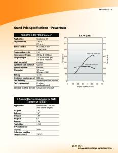
Fig. 3 The effect of aerodynamic downforce on cornering
force
4.00 3 .OO 2.00 I .oo
EJ
0.00 ~
1 .oo
-2.00 -3.00 -4.00 -5.00 0.50
0.60
0.70
Downforce on rear axle o/o of total
Fig. 4 The effect of centre of pressure on chassis balance 0 IMechE 1992
Chassis weight (kg) Front wheel weight (kg) Rear wheel weight (kg) Front wheel diameter (m) Rear wheel diameter (rn) Centre of gravity height (m) Centre of gravity position (% on rear) Centre of pressure position (% on rear) Downforce at 240 krn/h(kN) Drag at 240 km/h (kN) Roll stiffness (% on rear) Front track (m) Rear track (m) Wheelbase (m) Chassis width (m) Engine power (kW)
650.0 16.0 18.5 0.56 0.59
0.30 58.0
61.0 8.5 4.0
60.0 1.68 1.56 2.8 1 1.40 490.0
3 EXTERNAL AERODYNAMICS
3.1 Nose aerofoils
very little by the use of more sophisticated suspension models. Figure 3 demonstrates the predicted influence of downforce upon the cornering capability of the car through a variety of constant radius corners. A typical C,A value for a current Grand Prix car is approximately 3.2 m2. Not surprisingly, the greatest influence occurs at large radius corners where the car velocity is high and aerodynamic effects dominate. Around tight corners the performance of the car is influenced to a much greater degree by the mechanical properties of the chassis and the cornering force is affected relatively little by aerodynamic factors. Figure 4 shows the influence of the centre of pressure upon the cornering attitude of the car around corners of two different radii. For optimum performance and driveability the car should corner with a near-neutral attitude. Not only does Fig. 4 reveal the strong influence that the centre of pressure has upon the understeer or oversteer characteristics of the car but also the common problem of achieving neutral balance around corners of different radii. Full details of the test car that has been used for this analysis are given in Table 1. The inclusion of such a model in the modelling of a car around a complete circuit has been vresented by Dominy and Dominy (5).
D
269
The prodigious aerodynamic downforce of a modern Grand Prix car is generated from two main sources, the aerofoils and ‘ground effect’. The front wing (Fig. 1) is the most efficient aerodynamic device on the car. Except when closely following another car this aerofoil operates in an undisturbed airflow and in principle there is little problem in developing high downforce with relatively little drag using conventional aerofoil profiles [for example see references (6) and (7)]. The close proximity of the front wing to the ground provides a further performance enhancement since the airflow over the lower, suction side of the aerofoil is constrained by the ground and accelerates to a higher velocity than would otherwise occur, resulting in lower surface static pressures and therefore greater downforce. The change in the pressure distribution over a typical two-piece F1 front wing resulting from ground proximity is shown in Fig. 5. As the ground clearance is reduced the pressure distribution becomes more extreme until the flow is no longer able to withstand the adverse pressure gradient over the rear of the aerofoil and the wing stalls. Although some manufacturers have designed aerofoils specifically to operate close to the ground many have simply adopted ‘textbook’ designs, relying on track testing to determine their stall limit. Even if stalling is avoided the small changes of ride height that result from track undulations, roll and pitch may lead to significant downforce changes if the wing is mounted too low. Of equal significance are the corresponding changes to the centre of pressure of the car and together these factors can make the car extremely difficult to drive. Designers are therefore forced to compromise between optimum aerodynamic efficiency (small ground clearances) and acceptable bump and pitch sensitivity. The limited permitted span of each aerofoil makes it essential to control the tip effects that are associated with aerofoils of finite span. The simplest solution makes use of plane end-plates to maintain an approximately two-dimensional flow over the entire span which increases the aerodynamic loading towards the wing tips. This does not, however, eliminate the strong tip vortices that are generated and a recent development has been the adoption of semi-tubular guides along the lower edges of the end-plates in an effort to contain these vortices (Fig. 1). Proc Instn Mech Engrs Vol 206
R G DOMINY
270 1.51 "
"
"
'
"
'
"
'
'
"
"
'
"
'
"
~
4
I
. c
4
v
i
P I 4
v
0
100
200 300 Surface length
400
mm
Fig. 5 The effect of ground proximity on the pressure distribution over the front wing
A further design consideration is the influence of the wake from the front wings upon the rest of the car and in particular upon its cooling performance. In general, the greater the incidence of the aerofoil, whether a single element or a flapped design, the greater is the influence of its wake upon the cooling flow. Unfortunately, it is at slower circuits where the cooling air velocity through the radiator ducts is naturally reduced that the greater wing incidences are required to maximize downforce, thus compounding the cooling problem. A solution that has now been widely adopted is the use of flapped aerofoils in which the chord and camber of the outer section of the flap is very much greater than that at the chassis end (Fig. 1). Combining this aerofoil design with revised radiator intakes that are taller but narrower (thus retaining their frontal area) ensures that only the wake from the inner, less extreme, section of the wings impinges upon the cooling intake. The more disturbed air from the tip passes around the outside of the duct.
3.2 Rear aerofoils The air flow over the rear wing is highly complex. Unsteady, turbulent and often swirling incident flows arise from the upstream flow around the wheels, the front wings, the cockpit and driver, the engine intake, the mirrors and numerous other, lesser, influences. As a result the effective incident flow angle at the leading edge of the main wing may vary by as much as 20" across its span and the dynamic head is much reduced. Not surprisingly, high downforce cannot be generated at the rear of the car with anything like the same aerodynamic efficiency as at the nose. However, in order to provide the correct centre of pressure the rear wing is required to generate more than twice the downforce that is produced by the front aerofoils, and to achieve it the design engineers have to resort to the highly cambered, multi-element configurations that have become familiar in recent years. These designs, which resemble aircraft wings in their landing condition, produce high Part D : Journal of Automobile Engineering
downforce but are highly inefficient, and the associated drag has a major impact upon the top speed of the cars. However, it should be noted that the drag penalty is more than offset by the higher cornering speeds and by higher speeds at entry to and exit from the straights. The optimum balance between the conflicting requirements for high straight line speeds and cornering speeds is dependent upon the nature of the particular circuit. The racing regulations which limit the height and longitudinal position of the rear wing assembly indirectly dictate its size. Since the trailing edge position is governed by these regulations the only positional flexibility lies in the location of the leading edge. A high leading edge takes advantage of more uniform, higher velocity airflow but necessarily results in a smaller aerofoil. Dropping the leading edge allows a physically larger device to be used but it then operates in a less desirable incident airflow. Once again, compromise is necessary. The supplementary aerofoils that are often seen at the rear of the car, mounted low over the bodywork, provide very little benefit and reflect the desperate search for downforce generation at the rear of the car. Such aerofoils provide very much greater benefits when applied to closed wheel cars such as those governed by the Group C and IMSA racing categories (8). A commonly used aid to downforce generation is the Gurney flap, a 90" flap which is attached to the trailing edge of the aerofoil (Fig. 6). Katz and Largman (9) have shown that these devices allow the maximum lift coefficient of the wing to be increased although the precise mechanism by which this is achieved is not described. Work by the author has shown that the pressure distribution around the aerofoil element to which the flap is attached is significantly changed on both surfaces. On the pressure surface the stagnating flow ahead of the 90" flap gives rise to a large pressure rise over the entire surface and on the suction side the much reduced base pressure that is associated with the large wake from the flap enhances the low pressure on that surface. The high pressure on the upper surface is also seen to permeate upstream on to the pressure surface of the main element of the aerofoil. The overall effect is a substantial rise in @ IMechE 1992
AERODYNAMICS OF GRAND PRIX CARS
0
100
27 1
400
200 300 Surface length m ni
Fig. 6 The influence of the 'Gurney flap' on aerofoil pressure distribution
the downforce that is generated by the aerofoil, albeit with a large drag penalty.
3.3 Ground effect Since the initial development of 'ground effect' cars that has been described by Wright (10) the racing regulations have been regularly rewritten in order to limit the effect and hence to show the cars on safety grounds. At the time of writing the underside of the car must be completely flat between the front and rear wheels, which effectively eliminates ground effect in the form in which it was first developed. However, the high relative velocity between the underside of the car and the track, together with the low ground clearances that can be maintained using current suspension designs, allows downforce to be generated in essentially the same manner. Air flowing beneath the car accelerates around the sharp leading edge of the undertray which leads to a high-pressure stagnation point on the upper surface and a separation bubble below the entry lip (Fig. 7). Both of these phenomena add to the downforce of the car. The separation bubble reduces the effective cross-sectional area available to the flow beneath the car which then diffuses as the flow reattaches. As a consequence of the low ground clearance at which the car is running the increase in effective cross-section behind the separation results in significant diffusion. The result is a region of low pressure near the front of the undertray (Fig. 7).
The addition of a diffuser immediately behind the controlled flat bottom area creates a further zone of low pressure around the transition point between the undertray and the diffuser. Small radii here give rise to lower pressures but may lead to separation [for example see reference (ll)]. The pressure distribution beneath the car is also strongly influenced by the low-pressure zone behind the car into which the diffuser flow exhausts. Reducing this base pressure enhances the downforce but ony with an associated drag penalty. The variety of diffuser designs that have been used and discarded demonstrates the ongoing search for any slight advantage. The low-pressure zone beneath the car causes an inflow of higher pressure ambient air which weakens the impact of the ground effect and at the rear axle the effect has all but disappeared. Since the overriding problem of the aerodynamic design is that of achieving sufticient downforce at the rear of the car it is beneficial to position the low-pressure zone beneath the undertray as far towards the rear as possible. As the rearmost part of the flat undertray has little influence on the downforce generation the shorter overall length of the undertray that results is of little consequence. It is for this reason that the current generation of F1 cars has adopted raised nose designs which were developed into their current form by Tyrrell (Fig. 1). The sharp leading edge of the undertray and its associated low-pressure zone therefore begins at the front of the regulation flat section and not at the nose itself, thus moving the centre of pressure
Nose Motion shown relative to car Stagnation point
-4
-
- _ - _ - - - , - - - - z - - - ~
Diffusing flow
-- - --
- - - 4 - , 4 - 4 - 4 - -
Undertray
----*-,-------+-
\
d
\
\
\
\
\
\
\
\
Ground
Accelerating flow
Fig. 7 Airflow at the leading edge of the undertray (raised nose) 0 IMechE 1992
Proc Instn Mech Engrs Vol 206
R G DOMINY
272
rearwards. A further benefit of raising the nose is reduced sensitivity to pitch. Attempts have also been made to limit the flow of air under the sides of the car and thereby to maintain the low-pressure area beneath it over a greater length. Since the regulations no longer allow any kind of seal to bridge the space between the outer corner of the undertray and the ground alternative means must be sought. Much of the development here has been carried out not by the Grand Prix teams but by their Group C counterparts, who work with a very much greater degree of ground effect and substantially lower pressures beneath their cars. An effective approach to the problem has been to consider the two-dimensional component of the leakage flow across the car in the direction perpendicular to the forward motion of the car. In a manner similar to that at the front of the undertray, leakage flow may be reduced by the adoption of a sharp, horizontal ledge or 'skirt' along the side of the undertray (Fig. 1). 4 ENGINE INTAKE AND EXHAUST FLOWS 4.1 Intake design
If the dynamic head arising from the forward motion of the car is harnessed it is possible to raise the static pressure and hence the air density at the engine inlet. Consequently, more fuel may be burnt and more power produced while maintaining the same air-fuel ratio. The dynamic pressure may be related to the velocity of the car (assuming air to be incompressible at racing speeds) by the expression PU2 Ap = -
2
The static pressure is approximately that which would occur if the air flowed across the top of the injection trumpets and the total pressure is that which occurs if the flow is brought to rest relative to the car. For a car travelling at 200 km/h (a typical average speed around a Grand Prix circuit) the maximum available pressure rise is 1.85 kPa or 1.83 per cent of the ambient pressure (International Standard Atmosphere at sea level). If, for small changes of density, the power available from the engine is assumed to be proportional to the density of air, then the power increase due to the 'ram effect' for a 490 kW (657 b.h.p.) Grand Prix engine is approximately 9 kW (12 b.h.p.)-a small but significant gain. At higher speeds the gain will be greater (for example 4.7 per cent at 320 km/h). However, for a finite intake size the actual power gain will be less since the air will not be brought completely to rest, the ram pressure rise being dependent upon its frontal area and the engine air volumetric flowrate. Figure 8 shows the rise that is potentially achievable from a range of intake areas for a 3.5 litre engine running at 13000 r/min with a volumetric eficiency of 95 per cent. In this example a uniform inlet flow is assumed with no diffusion within the intake. Clearly the greatest power gains are achieved using the largest intakes. However, these lead to greater drag and to reduced downforce due to the disturbance of the airflow flowing on to the rear wing. Compromises are therefore required to balance any power gain against detrimental aerodynamic influences. For any chosen Part D : Journal of Automobile Engineering
.1
L
4: 3: 2-
Car speed = 100 kmih
I: 0-
0.00
- _ Negative represents restricted flow
0.02
0.04
0.06
0.08
0.10
Intake area m7
Fig. 8 The influence of engine air intake area on the ram pressure rise for a forward facing intake
intake area its shape is constrained by the close proximity of the driver's head and by a maximum bodywork height regulation. If the intake is made too small it may restrict the airflow to the engine at low velocities. 4.2 Wheels
The exposed wheels of Grand Prix racing cars provide the greatest single source of drag, accounting for between 35 and 50 per cent of the overall drag acting upon the car. The exact proportion will change according to the aerodynamic configuration that is chosen for a particular circuit. Smaller tyres would undoubtedly reduce the wheel drag, but in general it is the conflicting requirement to control tyre temperatures and achieve particular mechanical properties of the tyres that is the overriding influence upon their design. Since most of the leading teams are supplied by a single tyre manufacturer there is little to be gained by any one racing team from tyre size changes. Designers do, however, have some control over the interactions between the airflow around the wheels and that over the bodywork. The greatest changes in this area have occurred at the rear of the car. Before the abolition of full-length, ground effect diffusers the entire design of the car, both aerodynamically and mechanically, was compromised to maximize the massive downforce that was generated (5, 10). Engines, gearboxes, chassis and suspension systems were redesigned to optimize ground effect aerodynamics. One major aspect of the design was the use of the low-pressure region in the wake of the car to enhance the low-pressure zone that was created beneath it. To achieve this the rear bodywork was extended across the full width of the car and sealing strips were added between the body and the tyres to prevent ambient air from diluting the suction effect. Radiator exit flows were exhausted above the car and not into the base region for similar reasons. This large lowpressure region behind the car was accompanied by high drag, but this was much less influential on laptime than was the gain that was to be had from the downforce that was generated. However, the change to flat undertrays caused a dramatic loss of downforce and soon the appearance of the cars changed. The first of @ IMechE 1992
AERODYNAMICS OF GRAND PRIX CARS
the ‘new look’ cars was the Arrows A6, soon to be followed by the McLaren MP4. It was realized that since most of the downforce was now generated by the front and rear aerofoils the drag of the chassis could be reduced without significantly losing overall downforce; this was achieved by allowing air to flow between the rear tyres and the bodywork, thus reducing the base area and increasing the base pressure in one move. Further drag reduction was achieved by exhausting the radiator cooling flow into the base zone. The result was the now ubiquitous boat-tail form.
273 I
2.0
I
I
I
Radiator incidence
4
-
1.2 -
-
Car speed = 110 krnih
5 INTERNAL AERODYNAMICS: COOLING FLOWS
Cooling flows refer not only to the airflow that is required to cool the engine coolant and lubricant but also those flows that are necessary to cool the brakes, the engine ancillaries and on occasion the driver too. By far the most important in terms of the overall aerodynamic performance of a car are the radiator cooling flows. This is yet another area of design where compromises are abundant. The objective when developing the cooling system is to achieve adequate cooling with the minimum drag. Radiators are inherently high drag devices since for good heat-transfer properties they rely on large surface areas and their resistance to the airflow is usually specified in terms of their k factor, where
k = 2 -P1 -2 P z
(9)
Purad
A large k value implies high resistance and therefore high drag. For typical F1 water radiators ( k = 10) the resistance due to the radiator reduces the airspeed through the radiator duct to approximately 25 per cent of the forward speed of the car. For a single radiator with a frontal area of 0.2 m2 this results in a drag coefficient of 0.5 (based on the radiator frontal area and vehicle velocity) or approximately 8 per cent of the overall drag force acting upon the car. Because of the close spacing of the cooling fins on automobile water radiators the cross flow is more akin to that within a pipe than to flow past a body, with the result that the drag force changes not in proportion to (ur,d)2 but as an approximation to (urad)’.’(12). Since the heat transfer is approximately proportional to uradthe drag is reduced proportionally more than is the heat transfer if the airspeed through a radiator can be reduced. In practice the flow can be slowed by diffusing the flow between the intake and the radiator itself. For a given air mass flow the radiator will therefore be enlarged, but the heat transfer is little changed since the increased area and the reduced air speed effectively offset one another. However, the pressure drop across the radiator and hence the drag force will be reduced, resulting in enhanced efficiency. Such a treatment has two major drawbacks. The first is that a larger and therefore heavier radiator is required and the second is that the frontal area of the duct is increased which adversely affects the external airflow. The former problem must be considered in terms of a compromise between drag reduction and weight increase with additional considerations such as the impact on the weight distribution of the car. The latter drawback is easily overcome by inclining the radiator within the cooling duct (Fig. 9). By @ IMechE 1992
0.0
0
I
I
I
I
20
40
60
80
Radiator incidence deg
Fig. 9 The effect of radiator inclination on the ratio of heat transfer to drag
this method the ratio of the face area of the radiator to the duct intake area may be adjusted without changing the frontal area of the duct. The flows that occur in a duct of this configuration are complex and some restriction of the flow is inevitable, but careful detail design can minimize the effect and the results of Fig. 9 clearly demonstrate the effectiveness of the system. An often misunderstood but essential design feature is the need for the flow to be deflected through the radiator such that it passes through the matrix perpendicular to its face. Attempts to construct inclined radiators with specially constructed fins that are parallel to the axis of the duct have been unsuccessful since they do not increase the cross-sectional area of the matrix relative to the inlet duct and do not therefore slow the flow but act simply as thick, perpendicular matrices. 6 PROXIMITY TO OTHER VEHICLES
The aerodynamic forces acting upon a Grand Prix car are greatly reduced when the car lies in the influence of the wake generated by another car. At a vehicle separation that is typical of that occurring at the start of an overtaking manoeuvre the downforce may be reduced by as much as 36 per cent and the drag by 23 per cent (13). This results in a higher maximum speed but reduced cornering speeds. Of equal significance is a dramatic change in the centre of pressure, which results in a severe understeer through the corners. Reduced cooling efficiency is also evident and overtaking cars are often observed to drop back from the car ahead in order to cool the engine if overtaking cannot be achieved in a relatively short time. 7 CONCLUSIONS
The aerodynamic characteristics of Formula 1 racing cars are highly complex. In this study each of the major aerodynamic features of current Grand Prix cars has been discussed to give an appreciation of why the cars outwardly appear as they do. However, beneath the skin is a great deal of further aerodynamic detail that is beyond the scope of the study. Aerodynamic research continues apace and designs are continually changing, but it must be remembered that any change, however Proc lnstn Mech Engrs Vol 206
R G DOMINY
214
small, will interact in some way with other aspects of the design of the car. REFERENCES 1 Kuethe, A. M. and Chow, C. Foundations of aerodynamics, 4th edition, 1986 (John Wiley, New York). 2 MeCormick, B. W. Aerodynamics, aeronautics and flight mechanics, 1979 (John Wiley, New York). 3 Dominy, J. Frictional aspects of Formula 1 racing car performance. Trihology lnt., June 1981,14(3), 167-170. 4 Ellis, J. Vehicle dynamics, 1969 (London Business Books). 5 Dominy, J. A. and Dominy, R. G. Aerodynamic influences on the performance of the Grand Prix racing car. R o c . Instn Mech. Engrs, 1984,198D, 1-7. 6 Abbott, 1. H. and Von Doenhorn, A. E. Theory of wing sections, 1949 (McGraw-Hill, New York).
Part D: Journal of Automobile Engineering
7 Young, A. D. The aerodynamic characteristics of flaps. ARC R&M 2622, 1953. 8 Katz, J. and Largmnn, R. Experimental study of the aerodynamic interaction between an enclosed-wheel racing-car and its rear wing. Trans. A S M E , J. Fluids Engng, 1989,111, 154-159. 9 Katz, J. and Largman, R. Effect of 90 degree flap on the aerodynamics of a two-element aerofoil. Trans. ASME, .I. Fluids Engng, 1989,11,93-94. 10 Wright, P. G. The influence of aerodynamics on the design of Formula One racing cars. Int. J. Veh. Des., 1982,3(4), 383-397. 11 ESDU. Introduction to design and performance data for diffusers.. ESDU data item 76027, 1976. 12 Barton, N. A. An investigation of the performance of an inclined racing car radiator. Durham University undergraduate project report, School of Engineering and Applied Science, 1990. 13 Dominy, R. G. The influence of slipstreaming on the performance of a Grand Prix racing car Proc. Instn Mech. Engrs, Part D, 1990, 204(D1), 35-40.
0 IMechE 1992