A Novel O(n) Parallel Banker’s Algorithm for System-on-a-Chip Jaehwan John Lee and Vincent John Mooney III School of Electrical and Computer Engineering Georgia Institute of Technology Atlanta, Georgia, U.S.A.
�
jaehwan, mooney @ece.gatech.edu
Abstract This paper proposes a novel O(n) Parallel Banker’s Algorithm (PBA) with a best-case run-time of O(1), reduced from an run-time complexity of the original Banker’s Algorithm. We implemented the approach in hardware, which we call PBA Unit (PBAU), using Verilog HDL and verified the runtime complexity. PBAU is an Intellectual Property (IP) block that provides a mechanism of very fast, automatic deadlock avoidance for a MultiProcessor System-on-a-Chip (MPSoC, which we predict will be the mainstream of future high performance computing environments). Moreover, our PBA supports multiple-instance multiple resource systems. We demonstrate that PBAU not only avoids deadlock in a few clock cycles (1600X faster than the Banker’s Algorithm in software) but also achieves in a particular example a 19% speedup of application execution time over avoiding deadlock in software. Lastly, the MPSoC area overhead due to PBAU is small, under 0.05% in our candidate MPSoC example.
be ignorable issues, but will, if not properly addressed, become problems in the sharing of resources.
������� �
1
Introduction
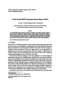
Recent trends show that System-on-a-Chip (SoC) technology enables multicore multithreaded systems on a single chip. An example of this is the Xilinx Vertex II Pro [1], which may contain multiple PowerPC processors and additional Intellectual Property (IP) cores. Furthermore, due to the ever increasing expansion of the Internet, a tremendous amount of multimedia related data is being created, edited and exchanged; this multimedia data is becoming larger with more varied and complicated encodings, requiring unprecedented processing power. To support such multimedia communication, numerous algorithms, specialized processors, image/video coding hardware modules and error isolation modules have been implemented and exploited [2]. Thus, we predict that in the near future, MultiProcessor SoC (MPSoC) designs will, as shown in Figure 1, have many Processing Elements (PEs) and hardware resources. In such future real-time MPSoCs, many processes will concurrently run and dynamically require and access such available on-chip resources. Not only that, but ensuring predictability and reliability in such MPSoCs will be much more difficult. In such systems, we predict that deadlock possibilities will no longer
custom logic
le reconfigurab logic
SP or pipelined D ’s SP multiple D hardware s semaphore I/O buffers memory allocator memory arbiter
PBAU
L1
PE1
L1
PE2
HW/SW L1
RTOS he L2 cac y r o m me
PE3
L1
PE4
L1
PE5
PE n: Processing Element n PBAU: Parallel Banker’s Algorithm Unit
Figure 1 A practical MPSoC
Therefore, we propose a novel Parallel Banker’s Algorithm and its hardware implementation and demonstrate its performance evaluation so that MPSoC programmers, who are reluctant to exploit deadlock avoidance approaches even as such approaches increase in importance, may be willing to adopt a faster hardware version of a deadlock avoidance approach.
2
Definitions and a Theorem
�� �� �� �������� �� ���
Definition 1 A safe sequence is an enumeration of all the processes in the system, such that for each , the resources that may request are a subset of the union of resources that are currently available and re[3, 4]. sources currently held by
� ���������������
�
� �� ���������� �� ! �
Theorem 1 A system of processes and resources is in a safe state if and only if there exists a safe sequence . If there is no safe sequence, the system is in an unsafe state [4].
" #� �$ �� �����%�� � &
If a system is in a safe state, completion of all the processes can be guaranteed by restricting resource usage in the system with a strategy – such as the Banker’s Algorithm [3, 4] – which executes one of the safe sequences. An “unsafe” state is not necessarily a deadlocked state because there still may exist a possibility that all processes terminate successfully. Definition 2 A single-instance resource is a resource that services no more than one process at a time. That is, while the
resource is processing a request from a process, all other processes requesting to use the resource must wait [5]. Definition 3 A multiple-instance resource is a resource that can service two or more processes at the same time, providing the same or similar functionality to all serviced processes [5].
resources – a counting semaphore with a group of I/O buffers, another counting semaphore with a group of multiple DSP processors and an SoCDMMU memory allocator [6] with a large L2 memory. Counting semaphores [3] are used to manage limited resources (including managing access to the resources). The MPSoC also contains a memory arbiter and a PBAU. PBAU in Figure 1 receives all requests and releases, decides whether or not the request can cause a deadlock and then permits the request only if no deadlock results.
Example 1
An example of a multiple-instance resource The SoC Dynamic Memory Management Unit (SoCDMMU) dynamically allocates and deallocates segment(s) of global level two (L2) memory between PEs with very fast and deterministic time (i.e., four clock cycles) [6]. In a system having an SoCDMMU and 16 segments of global L2 memory, which can be considered as a 16 instance resource, rather than having each PE (or process) keep track of each segment, PEs request segment(s) from the SoCDMMU (which keeps track of the L2 memory). In this way, not only can the overhead of tracking segments for each PE be reduced but also interfaces between PEs and segments can be simplified because PEs request segment(s) from one place (i.e., the SoCDMMU).
3
Previous Work and Motivation
In this section, we first mention related previous work and then introduce our approach. The fundamental deadlock avoidance approach is the wellknown Banker’s Algorithm (BA) in the operating system realm. Dijkstra first introduced BA for single multiple-instance resource systems [3], and later Habermann improved it for multiple-instance multiple-resource systems [4]. In BA, each process declares the maximum possible number of instances for each resource it may need. Given this information, as each resource request is made, an assignment is authorized provided that there exists at least one sequence of executions that does not evolve to a deadlock. The run-time complexity of the Habermann’s BA in software is , where and are the numbers of resources and processes, respectively. The efficiency of the algorithm was later improved to by Holt [7]. Even though BA was proposed a few decades ago, minor variations to BA are still being proposed for critical systems that can greatly benefit from the algorithm. For instance, in 2002, J. Ezpeleta at al. proposed a banker’s solution for deadlock avoidance in flexible manufacturing systems [8]. Recently, [9] has proposed a novel method of deadlock avoidance and its hardware implementation, which has a run, where and are time complexity of the numbers of resources and processes, respectively (see [9] for details). However, because the implementation of [9] is based on resource allocation graph [5] approach for singleinstance resources, it can only be used for systems exclusively with single-instance resources. Our implementation, the Parallel Banker’s Algorithm Unit (PBAU), on the contrary, can be used for not only a system with single-instance resources but also a system with multiple-instance resources as well.
������ � �
������ ��� � ��� ����� �
4
5
Methodology
Algorithm 1 shows our novel Parallel Banker’s Algorithm (PBA) for multiple-instance multiple-resource systems. PBA executes whenever a process is requesting resources and returns the status of whether the request is successfully granted or rejected due to the possibility of deadlock. PBA decides if the system is still going to be sufficiently safe after the grant. Before explaining the details of PBA, let us first show data structures as shown in Table 1 and notations for PBA as shown in Table 2. name Request[i][j] Maximum[i][j] Available[j] Allocation[i][j] Need[i][j]
�
�
To describe our system model, we show in the following example a possible MPSoC target. A future MPSoC We refer to the device shown in Figure 1 as a particular MPSoC example. This MPSoC consists of five Processing Elements (PEs) and three
��� ��� �� ������ �� ��� �� ���
notation
Work[j] Finish[i] Wait count[i]
� �
explanation request from process for resource maximum demand of process for resource current number of unused resource process ’s current allocation of process ’s potential for more (Need[i][j]=Maximum[i][j]-Allocation[i][j]) a temporary storage (array) for Available[j] potential completeness of process wait count for process to break livelock
��
�
�
TABLE 1 D ATA STRUCTURES FOR PBA
����� �
� � ������ ���
Target System Model
Example 2
We consider this kind of request-grant system with many resources and PEs shown in Figure 1 as our system model.
notation
array[][] or array[] array[i][] array[][j]
explanation a process a resource all elements of the array all elements of row of the array all elements of column of the array
��
TABLE 2 N OTATIONS FOR PBA
Algorithm 1
!#" $&% $&%
�
Parallel Banker’s Algorithm (PBA) PBA (Request[i][] for resources from process ) 1 STEP 0: makes Request[i][] for resources 2 STEP 1: if , Request[i][j] Need[i][j] /* means for all. */ 3 goto STEP 2 4 else ERROR 5 STEP 2: if , Request[i][j] Available[j] 6 goto STEP 3 7 else deny ’s request, increase Wait count[i] and return 8 STEP 3: pretend to allocate requested resources , Available[j] := Available[j] – Request[i][j] 9 10 , Allocation[i][j] := Allocation[i][j] + Request[i][j] 11 , Need[i][j] := Maximum[i][j] – Allocation[i][j] 12 STEP 4: prepare for safety check , Work[j] := Available[j] 13 14 , Finish[i] := false Let able-to-finish be ((Finish[i] == false) and ( , Need[i][j] Work[j])) 15 STEP 5: Find all such that able-to-finish 16 if such exists, 17 , Work[j] := Work[j] + such that able-to-finish Allocation[i][j] 18 for such that able-to-finish, Finish[i] := true 19 repeat STEP 5 20 else (i.e., no such exists) goto STEP 6 (end of iteration) 21 STEP 6: 22 if Finish[i] == true for all 23 then pretended allocations anchor; proceeds (i.e., SAFE) 24 else 25 restore the original state and deny ’s request (i.e., UNSAFE)
*
$&$&%% $&% $&$(%�
' '
!"
�#$ % � �
$
�
�
)"
$#%
!" !&"
'
PBA takes as input the maximum requirements of each process and guarantees that the system always remains in a safe state. Tables (data structures or arrays) are maintained of available resources, maximum requirements, current allocations of resources and resources needed, as shown in Table 1. PBA uses these tables to determine whether the state of the system is either safe or unsafe. When resources are requested by a process, the tables are updated pretending the resources were allocated. If the tables will be in a safe state, then the request is actually granted; otherwise, the request is not granted, and the tables are returned to their previous states. Let us explain Algorithm 1 step by step. A process can request multiple resources at a time as well as multiple instances of each resource. In Step 1, when a process requests resources, PBA first checks if the request does not exceed Need[i][] for the process. If the request is within its pre-declared claims, in Step 2 PBA checks if there are sufficient available resources for this request. If sufficient resources exist, PBA continues to Step 3; otherwise, the request is denied and the value of the wait counter (in variable Wait count[i] of Table 1) for the process increases to break livelock if necessary. In Step 3, it is pretended that the request could be fulfilled, and the tables are temporarily modified according to the request. In Step 4, PBA prepares for the safety check, i.e., initializes variables Work[] and Finish[]. In Step 5, PBA finds processes that can finish their jobs by acquiring some or all of available resources in Work[]. If one or more such processes exist, PBA adds all resources that these processes hold to Work[], then declares these processes to be able-to-finish (i.e., Finish[i] := true), and finally repeats Step 5 until all processes can finish their jobs. On the other hand, if no such process exists – meaning either all processes became able-to-finish or no more processes can satisfy the comparison (i.e., Need[i][j] Work[j] for all ) – PBA moves to Step 6 to decide whether the pretended allocation state is safe or not. In Step 6, if all processes have been declared to be able-tofinish, then the granted allocation state is in a safe state (meaning there exists at least a safe sequence by which all processes can finish their jobs in the order of processes having been declared to be able-to-finish); thus, the requester can safely proceed. However, in Step 6, if there remain any processes unable to finish, the pretended allocation state may cause deadlock; thus, PBA denies the request, restores the original allocation state before the pretended allocation and also increases the wait count for the requester. The gist of our approach is that because the operations in Step 5 are performed in parallel, if Need[i][j] Work[j] for all and for all are satisfied at the first iteration, PBA finishes at once, resulting in O(1) run-time. Such an example is given in Chapter V of [10] as “An example of resource allocation in a special case.” �
�
6
�
Implementation
Now we will describe implementation details including the architecture and circuitry of PBAU.
6.1 Architecture of PBAU Figure 2 illustrates PBAU implemented in Verilog HDL. PBAU is composed of element cells, process cells, resource cells and a safety cell in addition to a Finite State Machine (FSM) and a processor interface. request
processor interface request
request
FSM
element cell
element cell
element cell
process cell
element cell
element cell
element cell
process cell
element cell
element cell
element cell
process cell
resource cell
resource cell
resource cell
safety cell
Figure 2 PBAU architecture
The Processor Interface (PI) consists of command registers and status registers. PI receives and interprets commands (requests or releases) from processes as well as accomplishes simple jobs such as setting up the numbers of maximum claims and available resources as well as adjusting the numbers of allocated and available resources in the response to a release of resources. PI also returns processing results back to PEs via status registers as well as activates the FSM in response to a request for resources from a process. In the next subsection, we will describe in detail two of the cells in Figure 2.
6.2 PBAU Circuitry 6.2.1 Element Cell An Element Cell (EC), shown in Figure 3, performs two comparisons: Request[i][j] Need[i][j] and Need[i][j] Work[j]. The former comparison result (i.e., Request[i][j] Need[i][j]) is stored into a one-bit register. EC also stores Allocation[i][j] and Maximum[i][j]. EC emits Allocation[i][j] to Work[j] through freed out ij if the EC belongs to an able-to-finish process (i.e., Need[i][j] Work[j] for all ). In addition, there are two muxes, two subtracters and two adders. One adder is used to increase the number of allocation instances of the requested resource, and one subtracter is used to restore the temporarily increased number of instances if the safety test fails. Another subtracter is used to calculate the equation Need[i][j] = Maximum[i][j] – Allocation[i][j]. The other adder is used to make allocated instances (to this cell) available to later processes in a safe sequence. �
6.2.2 Resource Cell Each Resource Cell (RC, shown in Figure 4) corresponds to a multiple instance resource. RC has an Available[j] register that stores the number of instances of the resource. RC also has a Work[j] register that temporarily stores the number of resources in Available[j] (as shown in Step 4) plus resources to be released by able-to-finish processes during iterations of
emit_alloc_i pretend/restore
Work [j]
Request [j]
−
S0
+
S1
freed_in_ij
1
Allocation Register (4 bits)
latch_alloc_i
1 S1 Maximum Register (4 bits)
initialize_max_i
+
S0
− Need (4 bit wires)
Request
< Need
Need D
latch_compare_i
< Work
req_le_need_ij
Q
cell_reset
CLR
dard cell library [12]. We aimed to synthesize at a clock period of 4 ns. The synthesis result is shown in Table 3. The “Area” column denotes the area in units equivalent to a minimumsized two-input NAND gate in the library. PBAU5x5 represents a PBAU for five processes and five resources (each of which can have up to 16 instances). In case where an SoC contains five PowerPC 755 PEs (1.7M gates each) and a 16MB memory (33.5M gates), the area overhead in the SoC due to PBAU 20x20 is less than .05%. Synthesis Result Area (w.r.t. 2-input NAND) Number of lines of Verilog
freed_out_ij need_le_work_ij
pretend/restore
Request [j]
−
S0
+
S1
1
Available Register (4 bits)
ORed_latch_alloc_j initialize_available freed_out_sum _j
Request