(1o) Patent
No.: US 7,506,735 B2 Mar. 24, 2009 (45) Date of Patent:
( 12 ) United States Patent
Kloueek et al. (54) VIBRATION DAMPING AND HEAT TRANSFER USING MATERIAL PHASE CHANGES
OTHER PUBLICATIONS Kloucek, Pert, et al., "Computational Modeling of Vibration Damping in SMA Wires", Continuum Mechanics and Thermodynamics Manuscript No. Version 3.2, May 16, 2003, pp. 1-21. Kloucek, Pert, et al., "Thermal Stabilization of Shape Memory Alloy Wires", The International Society for Optical Engineering, Mar. 3-6, 2003, vol. 5049, pp. 23-34. Kloucek, Pert, et al., "Thermal Stabilization of Shape Memory Alloy Wires", SPIE Smart Structures and Materials, Mar. 3, 2003, vol. 5049, PowerPoint Presentation.
(75) Inventors: Petr Kloucek, Houston, TX (US); Daniel R. Reynolds, Oakland, CA (US) (73) Assignee: William Marsh Rice University, Houston, TX (US) (*) Notice: Subject to any disclaimer, the term of this patent is extended or adjusted under 35 U.S.C. 154(b) by 0 days.
* cited by examiner
(21) Appl. No.: 10/866,973
Primary Examiner Bradley T King (74)Attorney, Agent, orFirm—Conley Rose, P.C.; Rodney B. Carroll
(22) Filed:
(57)
Jun. 14, 2004
(65)
Prior Publication Data US 2009/0050428 Al
Feb. 26, 2009
(51) Int. Cl. F16F 7/10 (52)
(2006.01) U.S. Cl . .................... 188/378; 188/266.1; 188/274; 188/268
(58) Field of Classification Search ................. 188/274, 188/378, 266.1, 268, 276
See application file for complete search history. (56)
References Cited U.S. PATENT DOCUMENTS 5,005,678 A * 5,398,916 A
4/1991 Julien et al .................. 188/378 3/1995 Kramer et al.
5,808,837 A *
9/1998 Norton .................... 360/254.3
6,290,037 131 9/2001 Williams et al. 2003/0194320 Al* 10/2003 Villhard .................... 416/96 A 2004/0252005 Al* 12/2004 Villhard et al ............... 337/393
50--,,,
7 0 J (
ABSTRACT
A method and apparatus wherein phase changes in a material can dampen vibrational energy, dampen noise and facilitate heat transfer. One embodiment includes a method for damping vibrational energy in a body. The method comprises attaching a material to the body, wherein the material comprises a substrate, a shape memory alloy layer, and a plurality of temperature change elements. The method further comprises sensing vibrations in the body. In addition, the method comprises indicating to at least a portion of the temperature change elements to provide a temperature change in the shape memory alloy layer, wherein the temperature change is sufficient to provide a phase change in at least a portion of the shape memory alloy layer, and further wherein the phase change consumes a sufficient amount of kinetic energy to dampen at least a portion of the vibrational energy in the body. In other embodiments, the shape memory alloy layer is a thin film. Additional embodiments include a sensor connected to the material. 15 Claims, 5 Drawing Sheets
7)5
70
7)5
70
75
7)5
(
^
C
^
^
C
^` I 65
80
60
U.S. Patent
Mar. 24, 2009
Sheet 1 of 5
FIG. I
US 7,506,735 B2
U.S. Patent
Mar. 24, 2009
Sheet 2 of 5
US 7,506,735 B2
35
w
a
—45
40
Lu
I-L-Z-L1 DEFORMATION
FIG. 2
ZE
U.S. Patent
Mar. 24, 2009
US 7,506,735 B2
Sheet 3 of 5
55
50
I
F FIG. 3
70
50-,,,4,,
75
70
75
70
75
75 65 80
60
FIG. 4
70
75
70
75
70
75
70
75
80
50
FIG.5
VJ
U.S. Patent
Mar. 24, 2009
US 7,506,735 B2
Sheet 4 of 5
65
63 —N..,
FIG. 6
60
X 104 2.5
2 NC C
1.5 w
Z
w J v
1
Z Q U w 0.5
0 0
0.2
0.4
0.6
0.8
1
TIME (ms)
FIG. 7
1.2
1.4
1.6
1.8
2
U.S. Patent
Mar. 24, 2009
US 7 ,506,735 B2
Sheet 5 of 5
0.045 0.04
0.035 0.03
0.025 0.02
x
3 0.015 0.01 0.005 0 -0.005 0
5
10
15
20
25
30
35
40
45
50
[MM]
FIG. 8 PHASE PLOTS
t=0.2761 ma
0
50
t=0.5802 ma l.-851, 50
t=0.6823 ma ®L 8 ®^^ 8 ®^^ 8 ^11 85 0
® 50
t=1.7548 ma 1;::111®^!^ ^^^!®II;::II®^!^'^!^®III Him \-- 85 ^-- 85 ^— - 85 t-- 85 85 0
x [mm]
FIG. 9
50
US 7,506,735 B2 1 VIBRATION DAMPING AND HEAT TRANSFER USING MATERIAL PHASE CHANGES STATEMENT REGARDING FEDERALLY SPONSORED RESEARCH OR DEVELOPMENT This work was supported by grant NSF DMS-0107539, by contract number 03891-99-23 of the Department of Energy, and by grant SECTP-NAG5-8136 by NASA. CROSS-REFERENCE TO RELATED APPLICATIONS Not applicable. BACKGROUND OF THE INVENTION 1. Field of the Invention This invention relates to the field of phase changes in materials and more specifically to using phase changes in shape memory alloys and magnetorestrictive materials to dampen vibrations, cancel noise and increase heat transfer rates. 2. Background of the Invention With the growing sophistication of technology, there have been increasing needs to protect and enhance that technology. Such needs include damping vibrations and increasing the heat transfer rate in a wide number of applications. Vibrational energy is typically a problem because of the noise and stress involved that can cause reduced performance, damage, energy loss, and the like in applications. Conventional techniques for passive vibration damping include the use of visco-elastic materials. However, a drawback to using viscoelastic materials is their inherently poor ability to adapt to a variance in the system or application. Consequently, there is a need for an active, i.e., more efficient and versatile, way to dampen vibrational energy. Additional needs include increasing the heat transfer rate of materials, and dynamically enlarging the available surface area without reducing the available space for the application.
2 austenite phase to a martensite phase in the second surface, which increases the surface area of the second surface and the overall heat transfer rate. Further embodiments include a method for increasing the 5 surface area of a body. The method comprises securing to at least a portion of the body a shape memory alloy material. Upon exposure of at least a portion of the shape memory alloy to an amount of cooling, a phase change from an austenite phase to a martensite phase is induced in the shape memory io alloy, wherein the phase change increases the surface area of the body. The foregoing has outlined rather broadly the features and technical advantages of the present invention in order that the detailed description of the invention that follows may be 15 better understood. Additional features and advantages of the invention will be described hereinafter that form the subject of the claims of the invention. It should be appreciated by those skilled in the art that the conception and the specific embodiments disclosed may be readily utilized as a basis for 20 modifying or designing other structures for carrying out the same purposes of the present invention. It should also be realized by those skilled in the art that such equivalent constructions do not depart from the spirit and scope of the invention as set forth in the appended claims. 25
BRIEF DESCRIPTION OF THE DRAWINGS
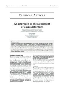
For a detailed description of the preferred embodiments of the invention, reference will now be made to the accompany30 ing drawings in which: FIG. 1 illustrates a hysteresis loop for a shape memory alloy; FIG. 2 illustrates a shape memory effect for a shape memory alloy; 35 FIG. 3 illustrates a sound damping material secured to a body; FIG. 4 illustrates a side view of the sound damping material of FIG. 3; FIG. 5 illustrates a top view of the sound damping material 40 of FIG. 3; FIG. 6 illustrates a side view of a heat transfer material having a shape memory alloy layer; FIG. 7 illustrates a kinetic energy history plot of a shape BRIEF SUMMARY OF SOME OF THE memory alloy; PREFERRED EMBODIMENTS FIG. 8 illustrates a displacement plot of a shape memory 45 alloy; and These and other needs in the art are addressed in one FIG. 9 illustrates a distribution of variants for a shape embodiment by a method for damping vibrational energy in a memory alloy wire. body. The method includes attaching a material to the body, wherein the material comprises a substrate, a shape memory 50 DETAILED DESCRIPTION OF THE PREFERRED alloy layer, and a plurality of temperature change elements. EMBODIMENTS The method further comprises sensing vibrations in the body. In addition, the method comprises indicating to at least a Phase changing materials can be used to dampen vibraportion of the temperature change elements to provide a temtional energy, increase surface area, cancel or reduce noise, perature change in the shape memory alloy layer, wherein the 55 and/or increase heat transfer in an attached body. For temperature change is sufficient to provide a phase change in instance, unevenly distributed internal oscillations of an at least a portion of the shape memory alloy layer, and further atomic lattice caused by phase changes in materials can wherein the phase change consumes a sufficient amount of spread through parts of the body. Such phase changes can be kinetic energy to dampen at least a portion of the vibrational caused by localized heating and cooling of shape memory energy in the body. 6o alloys. Cooling of shape memory alloys can also increase the An additional embodiment includes a heat transfer appasurface area of the alloys and/or increase heat transfer from ratus. The heat transfer apparatus comprises a first surface the body. Shape memory alloys have metallurgic properties with a heat transfer rate. In addition, the heat transfer appathat include the shape memory effect and temperature field ratus comprises a second surface comprising a shape memory dependent atomic lattice transformations, which are comalloy (preferably a shape memory alloy thin film), wherein 65 monly interpreted as phase changes. Temperature dependent the second surface covers at least a portion of the first surface. phases of shape memory alloys include a number of martenThe heat transfer apparatus includes a phase change from an site phases and an austenite phase. The austenite phase is
3
US 7,506,735 B2 4
typically strong, hard and rotationally symmetric, whereas the environment, preferably positioned at locations that the martensite phases are soft, deformable and less symmetric extract the largest amounts of vibrational energy from the than the austenite phase. A shape memory alloy can exhibit environment. Body 55 can comprise any material. For either or both of the austenite and martensite phases at once. instance, body 55 can comprise metal, plastic, and the like. FIG. 1 illustrates a theoretical hysteresis loop 5. When the 5 FIG. 4 illustrates a side view of damping material 50, and less symmetric phase martensite is heated, it can begin to FIG. 5 illustrates atop view of damping material 50. Damping structurally change into the austenite phase at the austenite material 50 comprises a substrate 60, a shape memory alloy start temperature 10. The phase change to austenite can be layer 65, a heating element 70, and a cooling element 75. completed at the austenite finish temperature 15. When the Substrate 60 can be any material suitable forbeing secured to austenite phase is cooled, it can begin to change to the mar- io body 55 and supporting shape memory alloy layer 65. tensite phase at the martensite start temperature 20. It can Examples of suitable materials for substrate 60 include kev complete its phase change to martensite at the martensite lar, polymers, fibers from carbon nanotubes, and the like. finish temperature 25. It is to be understood that none of the Shape memory alloy layer 65 can comprise any shape temperatures 10, 15, 20, and 25 are the same. The hysteresis memory alloy. Examples of shape memory alloys include 30 is demonstrated by the area between these transformation 15 NiTi, NiAl, CuA1Ni, CuZnAl, and the like. Shape memory curves. The hysteresis 30 provides a measure of the energy alloy layer 65 can be any thickness, preferably a thin film. absorbed or released by the material during the overall trans- Heating element 70 can be any device suitable for heating a formation. localized region of shape memory alloy layer 65. Suitable FIG. 2 illustrates a theoretical shape memory effect heating elements 70 include any type of resistive heating between phases. Without limiting the present invention, it is 20 elements, such as ohmic heating elements. Cooling element believed that the behavior of shape memory alloys is based on 75 can be any device suitable for cooling a localized region of the temperature dependent atomic-scale phase transformashape memory alloy layer 65. An example of a suitable cool tion. This transformation can be a result of the material's ing element 75 is a Peltier exchanger. A sensor 80 can be microstructure changing to minimize the strain energy at a connected to heating and cooling elements 70, 75 of damping given temperature. For instance, in the austenite phase 35, the 25 material 50. Sensor 80 can be any type of sensor suitable for microstructure can maintain a single crystallographic orien- sensing vibrations. Examples of suitable sensors 80 include tation. Upon cooling of the shape memory alloy, it can change accelerometers and vibration sensors such as 4-20 mA loop into the martensite phase 40, which involves the creation of powered sensors suitable for 10 Hz to 4,000 Hz frequency martensitic variants that have a plurality of crystallographi- range. Sensor 80 can be secured to damping material 50 or cally equivalent habit planes. It is believed that such variants 3o remote to damping material 50. Sensor 80 is not limited to are created by a mechanism referred to as twinning, in which being secured to an end of damping material 50 as illustrated the atoms across a twinning plane achieve displacement with in FIGS. 4 and 5 but instead can be secured to any suitable mirror symmetry. In the martensite phase 40, the shape location on damping material 50. In addition, damping mate memory alloy is capable of another transformation to the rial 50 can have any desirable shape. One skilled in the art deformed martensite 45. At this state, the full atomic lattice 35 would readily understand to select an appropriate shape for a can be comprised of a single crystal variant, i.e., the twinning desired application. does not occur. Martensite may be deformed to strains of up It is to be understood that the damping can occur when to 8% without any effects of plasticity. When the shape distributed vibrations generated by the phase transition (e.g., memory alloy is in its martensite phase 40 or deformed mar- martensite to austenite or vice-versa) spread in body 55. The tensite phase 45, its microstructure returns to its prior auste- 4o damping can also occur when unevenly distributed vibrations nite phase 35 upon reheating to austenite finish temperature generated by such phase transitions are spread in parts of 15, wherein the shape memory alloy can resume its original body 55. Phase transitions in shape memory allow layer 65 shape and rigidity. can be sufficient for damping vibrations within the time the It has been discovered that thermally activated controls for onset of the martensitic or austenitic phase transition can be triggering contraction and elongation in shape memory alloys 45 induced. Thermally activated controls can be used to control can be used to dampen vibrational energy, increase surface such transitions. Thermally activated controls determine and area, cancel or reduce noise, and increase the heat transfer rate control the heating and cooling scheme at which the localized of materials. Thermal control includes the formation of local- phase changes occur. Such controls include determining the ized and distributed transformation regions throughout the number and spacing of heating and cooling elements 70, 75; shape memory alloy. When the shape memory alloy is 5o determining the amount of heat added by heating elements attached to a body, vibrations in that body can be dampened 70; determining the rate of heat reduction by cooling eleby the phase transformations in the shape memory alloy. ments 75; and determining the duration of time at which the FIG. 3 illustrates a damping material 50 attached to a heat is added. Therefore, damping material 50 can have any desired material body 55. The damping material 50 comprises number of heating and cooling elements 70, 75, as detera shape memory alloy thin film material having controlled 55 mined by the controls. The methods and procedures for deterformation of localized and spaced non-planar transformation mining such activated controls are taught in Kloucek et al., regions. Damping material 50 can be attached to the desired "Thermal Stabilization of Shape Memory Alloy Wires," material body 55 in any suitable way. For example, damping Smart Structures and Materials 2003: Modeling Signal Processing, and Control, Vol. 5049 (2003) and Kloucek et al, material 50 can be attached by glue, welds, screws, and the like. The glue can be any suitable glue for a desired applica- 60 "Computational Modeling of Vibration Damping in SMA tion. Examples of suitable glue include ethyl cyanoacrylate Wires," Continuum Mechanics and Thermodynamics 2004, and methalcrylate resin. The damping material 50 can be (the "Kloucek" articles) both of which are incorporated by attached to any suitable location on body 55. In some embodi- reference herein in their entirety. The Kloucek articles teach ments, the location of damping material 50 on body 55 is that a dynamic model for the temperature control of shape based on frequency distribution through body 55. In such 65 memory alloys can be obtained through computational modembodiments, the placement of damping material 50 can be eling based on a carefully built Helmholtz free energy, conpositioned at locations that extract vibrational energy from servation of linear momentum and conservation of energy.
US 7,506,735 B2 5
6
The model provides a characterization of the thermodynamic behavior of shape memory alloy layer 65 for any given type of shape memory alloy. The model is given by the following equations (1)-(4): poa,,u=Div(poa,T+aa,F)+pob
(1);
poC,a,6=7i^((pooa F 0 2T+a,Fa)a,F)+K Div(det(F) (F7F) -10e) +por
(2);
T(F,8)—X(8) Wn,(F)+(1—x(8)) WA (F)+c,(6-61n6)
(3);
WO
(4)
X(BM) = 1 , X(B A) = 0 , X(B C) =
WA
WMM +WAWO
In the equations, p o represents the referential density, a represents partial derivative, T represents Helmholtz free energy, a represents deformation of the body with respect to a referential coordinate system, 0 represents absolute temperature, b represents body force, t represents time, a represents viscosity coefficient, F represents deformation gradient, K represents heat conductivity, WA represents austenite energy isotherm, Wm represents martensite energy isotherm, cp represents specific heat capacity, r represents heat exchange with the environment, Div represents divergence, T represents transposition, Tr represents trace, x represents isotherm profiles interpolation function, I represents the identity matrix, U, represents a martensite variant, O M represents the martensite finish temperature 25, O A represents the austenite finish temperature 15, and 0 c represents the critical transformation temperature at which both the austenite and martensite phases may co-exist. The model given by equations (1)-(4) provides a nonlinear system of partial differential equations. The solution of the model for a type of shape memory alloy provides the thermodynamic behavior of that particular shape memory alloy. It is to be understood that one of ordinary skill in the art can make such a solution of the model. Furthermore, the Kloucek articles teach that through the definition of the martensite and austenite energy isotherms the model, in combination with the solution method using a viscosity-based homotopy applied at the brief moments of the phase transition, can be tailored to evaluate the thermodynamic response of any shape memory alloy. Based upon the model and the type of shape memory alloy used, shape memory alloy layer 65 can be heated using the control represented by equation (5); r(x,t)=A sin (2pi*(x/l+t/w))Watts,
(5)
where the amplitude depends on a particular shape memory alloy to be used and the power of the available heating and cooling elements. This constant A for a particular shape memory alloy can be selected from a range of 0 to 100. The constant 1 provides a measure of the localization of the heating and cooling controls. The constant w may be varied to allow for a time-dependent nature of the thermal control. In the equation, x represents spatial variable, and t represents time. The following describes an exemplary embodiment of the present invention as illustrated in FIGS. 3-5. Damping material 50 is attached to body 55. Body 55 can be any type of body. The number and spacing of heating and cooling elements 70, 75 are selected based upon an effective active control of the system of partial differential equations (1)-(4) described above with the Helmholtz free energy tailored to the desired shape memory alloy. It is to be understood that the molecular structure of the crystal lattice can depend on the
minimum energy states of the strain energy. In a state of thermal equilibrium, any mechanical equilibrium configuration of the lattice particle can correspond to a minimum of the free energy functional with respect to the deformation gradi5 ent. The form of the free energy of the present invention provides a phenomenologically-based, nonlinear model for shape memory wires, as presented in the Kloucek articles. However, through incorporation of the relevant material constants, it is materially tunable, which allows for control over 10 both the nonlinear physics of shape memory alloys as well as the material constants of particular materials. Sensor 80 is secured to damping material 50. In alternative embodiments (not illustrated), sensor 80 is not secured to damping material 50 but is instead remote to damping mate15 rial 50. When sensor 80 detects vibrations in or approaching body 55, it signals to heating elements 70 and cooling elements 75 to apply heat and cooling, respectively, to shape memory alloy layer 65 according to the control equation (5). Such heating and cooling can cause localized areas of shape 20 memory alloy layer 65 to change phases from martensite to austenite and vice-versa. This heating and control allows for both a localization of the temperature change control, as well as a motion of the temperature change in time. Due to the form of this control, there can be a large number of full sine waves 25 periodically heating and cooling the body. Furthermore, due to the factor dividing the time, the control can move along the length of the body, which allows the temperature of the highly-localized regions to reach the transformation temperatures. The control can move at any rate along the length of the 3o body, preferably at a slow rate. It is to be understood that this three-parameter (amplitude, localization and speed) form of the heating and cooling supply comprises an embodiment of the thermal control and is an illustrative example for understanding how localization of the thermal control benefits the 35 vibrational damping. The thermally-induced phase transformation can occur in two stages. The first of these occurs at the onset of the atomic lattice symmetry change. The second stage of the phase transformation can occur after occurrence of the first stage. The second stage may occur due to the latent 4o heat. The resulting phase change can cancel a large portion of the vibrational energy in body 55. The cancellation may occur due to the generation of non-synchronized spurious vibrations caused by the phase change. The kinetic energy can slowly decrease as the temperature increases. FIG. 7 is an 45 illustration of a kinetic energy time history, which shows such a decrease. At the onset of the first stage in the phase transformation, the kinetic energy drops. When this first stage of the phase transformation is complete, there is a spike in the kinetic energy before the second stage of transformation 5o begins. However, when the second stage is complete, the overall kinetic energy in the shape memory alloy layer 65 is significantly smaller than when the simulation began. Without being limited by theory, it is believed that such processes may be conversion between various kinds of energy. For 55 instance, after the initial wave hits the shape memory alloy layer 65, vibrations oscillate rapidly, with significant amounts in both the kinetic and potential energy states. Then, as the temperature is increased, the energetic metastability of the martensite phase increases. The increase in metastability cor6o responds with a conversion of a significant amount of the kinetic energy to potential energy in the shape memory alloy layer 65. As the phase transition itself occurs, the potential energy reaches its peak, causing a brief calm in the body before the first transformation changes an amount of the 65 shape memory alloy layer 65 into the austenitic state. Such a transformation can increase the kinetic energy dramatically. In addition, such transformation can occur very suddenly. As
US 7,506,735 B2 7
8
the second stage of the phase transition is beginning, this kinetic energy is converted into potential energy. When the full phase transformation is complete, the potential energy can be released. When sensor 80 reads that the vibrational energy in body 55 is reduced below a desired level, sensor 80 communicates to heating elements 70 to stop applying heat and communicates to cooling elements 75 to cool localized areas of shape memory alloy layer 65 to change the phase back to martensite. Such cooling can occur according to the control (5). It is also to be understood that when the phase is changed to martensite that the surface area of damping material 50 can be microscopically increased and that when the phase is changed to austenite that the surface area of damping material 50 can be microscopically decreased. Without being limited by theory, it is believed that such microscopic increase or decrease is caused by shape memory alloy layer 65 forming a non-planar microstructure to achieve an equilibrium state. It is to be understood that damping vibrational energy can result in damping sound as well as vibrations. In alternative embodiments (not illustrated), more than one sensor 80 is connected to at least one of the heating and cooling elements 70, 75. Based upon the excitement of a heating and/or cooling element, the control given by equation (5) can be initiated. In other alternative embodiments (not illustrated), a protective coating can be applied to damping material 50. The protective coating can be any material suitable for protecting at least a portion of damping material 50. The protective coating can include silicon, polymers, and the like. The protective coatings can cover any portion or substantially all of damping material 50. Examples of applications comprising body 55 that have vibrations of which damping material 50 can dampen include satellites, car CD receivers, drills, large bodies (for instance engines), platforms, microscopy, music speakers, and the like. In some embodiments, damping material 50 can be placed at any suitable location on a body 55. In other embodiments, damping material 50 can be placed at locations on a body 55 based on frequency distribution. FIG. 6 illustrates a heat transfer material 63 that comprises substrate 60 and shape memory alloy layer 65. In such an embodiment, heat transfer material 63 can be attached to a portion or all of the surface of any type of body. When sufficient cooling is added to heat transfer material 63 to change at least a portion of shape memory alloy layer 65 to its alternative martensite phase from its parent austenite phase, at least a portion of shape memory alloy layer 65 can rise microscopically. The surface area of heat transfer material 63 and the material body can thereby be increased. The surface area can also be increased by changing the phase from one martensite variant to another by changing the temperature. Such an increase in surface area can increase the heat transfer from the material body. For instance, heat transfer material 63 can be attached to an appropriate area of a heat exchanger such as the cool side of the exchanger or any other suitable area. For example, heat transfer material 63 can be attached to cooling tubes of a shell-and-tube heat exchanger. When a cooling fluid is added to the heat exchanger, at least a portion of shape memory alloy layer 65 can change to its martensite phase by the reduction in temperature to below the martensite start temperature 20 of the shape memory alloy layer 65, which thereby increases the surface area of the exchanger. Such increase in surface area can facilitate the heat transfer from the fluid. It is to be understood that one skilled in the art can select a suitable shape memory alloy having a martensite
phase change start and finish temperature 20, 25 that are within the temperature of the fluid. It is to be understood that the present invention is not limited to a shape memory alloy layer but can include other embodiments of shape memory alloy configurations such as segments of shape memory alloys.
5
EXAMPLE A wire made of NiTi alloy with the parameters given by Table 1 and having a small cross-sectional area, 2x10 -$ m2, was unevenly heated using the following control:
10
r(x,t)=64.5 sin (2pi*(x/10+t/2))Watts.
The duration of the experiment was 2 ms. At the end, most of the vibrational energy was eliminated. These results were analyzed in relation to the locality of the phase transformations. The sudden phase transformation resulted in an abrupt burst of kinetic energy that then resonated at the characteristic 20 speed of the austenitic phase in the wire. The localized phase transformations of this example induced bursts of vibrational energy. It is believed that the distributed nature of the phase transformation regions left regularly-spaced regions in which these vibrations travel. Since the induced vibrations travel at 25 the same speeds through these untransformed regions, the self-cancellation of such anti-phase vibrations resulted in the overall damping observed in this experiment. About 80% of the vibrational energy was eliminated at the onset of the phase transition at about 0.6 ms. 15
30
TABLE 1 NiTi material constants used within the calculations 35 Constant value
Units
Description
6.45 x 10 3 kg M-3 density K 10 W m-' K-1 thermal conductivity cP 322 J kg-' K-1 specific heat capacity po
Ea 7.5 x 10 10 Pa Em 2.8 x 10 10 Pa 0.05 m 40 L 2 x 10 -' mZ P 350 K O A 335 K 6c 320 K OM
austenite elastic modulus martensite elastic modulus length of wire cross-sectional area of wire austenite finish temperature critical transition temperature martensite finish temperature
45
The results are illustrated in FIGS. 7 and 8. FIG. 7 illustrates the kinetic energy history, and FIG. 8 illustrates a snapshot of displacement in the midst of the overall martensitic phase transformation at t-0.9644 ms. FIG. 9 shows the distributionofmartensitic variants for the wire during the experi50 ment. The light region 85 shows placements of the heating units along the length of the wire. It was observed at time t-0.5 ms that the phase transformation began in the wire at the many local peaks of the thermal control. It was further observed that the transforma55 tion occurs suddenly in locally isolated areas of the wire, which again resulted in a small kinetic energy increase. As illustrated by the results in FIG. 7, the resulting vibrations cancelled each other out. Although the present invention and its advantages have 6o been described in detail, it should be understood that various changes, substitutions and alterations may be made herein without departing from the spirit and scope of the invention as defined by the appended claims. 65
What is claimed is: 1. A method for damping vibrational energy in a body, comprising;
US 7,506,735 B2 9
10 7. The method of claim 1, wherein the plurality of tempera(A) attaching a damping device to the body, said damping device comprises a substrate, a shape memory alloy ture change elements comprise at least one cooling element layer disposed on at least a portion of the surface of said and further comprising indicating to the at least one cooling substrate, and a plurality of temperature change eleelement to cool the shape memory alloy layer, wherein the ments disposed on the shape memory alloy layer, 5 cooling is sufficient to provide a phase change in at least a wherein said damping device is in continuous and direct portion of the shape memory alloy layer to a martensite phase. contact with the surface of the body; 8. The method of claim 1, wherein step (B) is accomplished by a sensor. (B) sensing vibrations in the body; and 9. The method of claim 8, wherein the sensor is attached to (C) in response to the sensed vibrations, using a sinusoidal model based upon amplitude, localization, and speed to io the damping device. 10. The method of claim 1, wherein step (C) is accomcontrol each temperature change element so as to proplished when the vibrations are from about 10 Hz to about vide a temperature change in localized regions of the 4,000 Hz. shape memory alloy layer and dampen the vibrational 11. The method of claim 1, wherein the damping device energy in the body. 15 further comprises a coating that covers at least a portion of the 2. The method of claim 1, wherein the body is a drill, a shape memory alloy layer. platform, a large body, or a music speaker. 12. The method of claim 11, wherein the coating comprises 3. The method of claim 1, wherein the substrate comprises silicon or a polymer. polymers or fibers from carbon nanotubes. 13. The method of claim 1, wherein the shape memory 4. The method of claim 1, wherein the shape memory alloy 20 alloy layer is a thin film. comprises NiTi, NiAl, CuZnAl or CuA1Ni. 14. The method of claim 1, wherein step (C) is accom5. The method of claim 1, wherein the temperature change plished by a control. elements are sufficiently spaced to provide localized phase 15. The method of claim 1 wherein the sinusoidal model changes in the shape memory alloy layer. comprises the following equation: 6. The method of claim 1, wherein the plurality of tempera- 25 r(x,t)=A sin(2pi*(x/10+t/2))Watts ture change elements comprise at least one heating element whereinA represents amplitude and is a number ranging from and further comprising indicating to the at least one heating 1 to about 100, t is time in milliseconds, and x is a number element to supply heat to the shape memory alloy layer, ranging from 0 to L, wherein L is the length of the shape wherein the heat is sufficient to provide a phase change in at memory alloy layer. least a portion of the shape memory alloy layer to an austenite 30 phase.