Water Corporation
Odour Management Plan for Alkimos Wastewater Treatment Plant
November 2009
Consulting Environmental Engineers
Alkimos Odour Management Plan Table of Contents 1. 2. 3. 4. 5. 6. 7. 8. 9. 10. 11. 12. 13. 14. 15. 16. 17. 18. 19. 20. 21. 22. 23. 24. 25. 26.
Introduction to Odour Management Plan ................................................................. 2 Scope of Work ......................................................................................................... 3 Development of Odour Management Plan............................................................... 4 Staged Development of Alkimos Plant..................................................................... 5 Stages 1 and 2 – Concepts for Odour Control....................................................... 10 Design – Odour Control for Preliminary Treatment................................................ 11 Design – Odour Control for Secondary Treatment ................................................ 12 Design – Odour Control for Sludge Handling......................................................... 13 Design – Odour Treatment Units ........................................................................... 14 Design – Commitment to Bioscrubbers.............................................................. 18 Design – Odour Modelling.................................................................................. 21 Design – Compliance with Odour Criteria .......................................................... 22 Design – Size of the Stack ................................................................................. 23 Design – Sulphur Emission ................................................................................ 25 Commissioning – Bioscrubber Acclimatisation................................................... 26 Commissioning – Performance Testing ............................................................. 26 Commissioning – Balancing Duct Flows and Pressures .................................... 26 Commissioning – Verification of Performance ................................................... 27 Operations – Standard Operating Procedures ................................................... 27 Operations – Replacement of Odour treatment unit Media ................................ 28 Monitoring – Regular Odour Monitoring ............................................................. 28 Monitoring – Complaint Registration and Response .......................................... 29 Contingency Plans for Upsets or Maintenance .................................................. 29 Contingency Plans in the Event of Exceedances............................................... 30 Reporting and Re-design as Required ............................................................... 31 Summary of Odour Management Plan............................................................... 32
Figure 1 Figure 2 Figure 3 Figure 4 Figure 5 Figure 6 Figure 7 Figure 8
Proposed Stage 1 Plant at Alkimos .............................................................. 8 Proposed Stage 2 and Stage 3 Plant at Alkimos .......................................... 9 Layout of Proposed Stage 1 Odour Treatment Units at Alkimos ................ 16 Predicted Odour Contours- Stage 1 – Stack at 2,400 OU .......................... 19 Predicted Odour Contours- Stage 1 – Stack at 4,800 OU .......................... 20 Predicted Odour Contours- Stage 1 – Stack at 4,800 OU .......................... 23 Predicted Odour Contours- Stage 1 – 70 m High Stack ............................. 24 Predicted Ground Level Concentration of Sulphur ..................................... 25
Table 1 Table 2 Table 3 Table 4 Table 5
Odour Management in Design, Commissioning and Operations .................. 4 Air Extraction Rates in Stages 1 and 2 of Alkimos Plant............................. 11 Estimated Odour Emissions from Alkimos WWTP...................................... 21 Verification Testing and Reporting - Alkimos WWTP.................................. 27 Alkimos Odour Management Plan: ............................................................. 32
CEE-Ver03-Nov2009
Odour Management Plan for Alkimos Treatment Plant |2
1.
Introduction to Odour Management Plan
The objective of the Odour Management Plan is to ensure that the Alkimos WWTP is designed, constructed and operated to manage the potential impacts of odour to within the 600 m buffer zone allocated by the Metropolitan Regional Planning Scheme. This buffer is less than the 800 m zone requested by the Water Corporation to allow development of a full secondary treatment plant with on-site sludge handling at a capacity of 160 ML/d. Thus very careful control of odours will be required at all stages of design and operation of the plant. The specified maximum odour level at the boundary of the buffer zone is 5 odour units (OU) for 99.9 per cent of the time, as proposed by the Water Corporation in the Works Approval Application and specified in Ministerial Condition 12.7 for the development of the Alkimos treatment plant. Keeping odours at the boundary of the buffer zone within this odour limit will ensure that there is no noticeable odour at residences beyond the buffer zone. A particular feature of the Alkimos site is that the plant is located in a deep excavation (see phot on cover of this document). Temperature and wind patterns create a temperature inversion across the top of the hole on many nights per year. Under such conditions, the air in the excavated hole below the inversion can be considered as a “pond”. During the night hours, fugitive odours will accumulate in the ponded air. The quickening wind speed and rising temperatures in the morning release the air from the pond, producing a flow of potentially odorous air from the treatment plant over the land to the west and south-west. The effect of ponding is to concentrate the release of odours over a short period in the early morning. Control of diffuse odour emissions from all parts of the treatment plant is essential to achieve the objectives of the Water Corporation and keep odours below the threshold of causing nuisance at properties outside the buffer zone. The requirements for the Odour Management Plan include a description of the odour control measures to be adopted to limit odour releases (covers, odour treatment units and stacks), periodic monitoring during operations, odour modelling, contingency plans and complaint procedures. The Corporation is required to ‘implement the plan’, which means that all operations must use the odour control facilities provided in design and document the procedures to be followed in operations and maintenance to keep odour emissions within the levels necessary to meet the objective. The Odour Management Plan has been developed to manage the potential impacts of odour for Stages 1 and 2 of the Alkimos plant (to 2035) – a new odour management plan would be required for subsequent stages. A summary of the Odour Management Plan is given in the final section of this document.
CEE-Ver03-Nov2009
Odour Management Plan for Alkimos Treatment Plant |3
2.
Scope of Work
Ministerial Condition 12 for the Alkimos WWTP states that: Prior to commencement of operation, the proponent shall prepare and submit an Odour Management Plan to manage the impacts of odour on health and safety. The Odour Management Plan shall address: 1. Initial dynamic olfactory determination (soon after commissioning as part of proving performance of the odour scrubbers); 2. Biofilter acclimatisation period; 3. Procedures for replacement of scrubber media; 4. Regular checks of loading to ensure that flow and loading is balanced and to identify and correct any short circuits; 5. Size of the stack; 6. Compliance with odour criteria and trigger mechanisms for remedial actions; 7. Regular qualitative determination of odour from the facility; 8. Odour surveys every five years; 9. Contingency plans during upset or maintenance conditions; 10. Contingency plans in the event of exceedances; 11. Complaint registration, investigation and response. In preparing the Plan, the proponent shall consult with the Environmental Protection Authority. Every requirement is addressed in the Alkimos Odour Management Plan, as outlined in the table below. No 1 2 3 4 5 6 7 8 9 10 11
Requirement Initial olfactory determination Biofilter acclimatisation period Replacement of scrubber media Checks of flows and loading Size of the stack Compliance with odour criteria Regular odour monitoring Odour surveys Contingency plans for upsets or maintenance Contingency plans in the event of exceedances Complaint registration and response
CEE-Ver03-Nov2009
Covered in Section Commissioning - 16 Commissioning – 15 Operations – 20 Operations – 18 Design – 13 Design – 11 Operations – 21 Monitoring – 21 Contingency plans – 24 Contingency plans - 22 Monitoring
Odour Management Plan for Alkimos Treatment Plant |4
3.
Development of Odour Management Plan
There are several stages in the development and operation of a wastewater treatment plant and the components of the Odour Management Plan have been arranged so that they can be addressed in the correct sequence. The stages of development, and the works required to achieve effective control of odours in accordance with the Ministerial Condition and the environmental policies of the Water Corporation, are shown below in Table 1. Table 1 Odour Management in Design, Commissioning and Operations Stage in Development
Odour Management Task
Design
Concept for odour control Design of covers and odour capture Odour inventory Odour modelling Compliance with odour criteria Monitoring equipment Size of the stack Specification of design requirements
Commissioning
Bioscrubber acclimatisation period Initial olfactory determination Balancing duct flows and pressures Verification of performance
Operations
Standard operating procedures Checks of flows and loading Replacement of scrubber media Regular odour monitoring
Operations – contingency plans
Contingency plans for upsets or maintenance Contingency plans in the event of exceedances
Monitoring
Complaint registration and response Odour surveys Reporting and re-design as required
The procedures to be followed according to this Odour Management Plan are summarised for ready reference in Section 26, the final section of this document.
CEE-Ver03-Nov2009
Odour Management Plan for Alkimos Treatment Plant |5
4.
Staged Development of Alkimos Plant
It is planned to develop the Alkimos WWTP in several stages so that the increase in plant capacity matches the growth in flows to the plant. Current plans for the stages in development are as follows: • Stage 1 – 20 ML/d – provides capacity from 2010 to 2025 • Stage 2 – 40 ML/d – provides capacity from 2025 to 2035 • Stage 3 – 80 ML/d – provides capacity from 2035 to 2050 • Stage 4 – 120 ML/d – provides capacity from 2050 on. . In about 2045, a decision will be made about subsequent expansion of the plant from 80 ML/d to the larger capacity necessary to handle wastewater flows after 2050. The proposed ultimate capacity of the Alkimos WWTP is 160 ML/d which may be reached late in the century. There are several options to be considered in 2045, including adding primary treatment, which will reduce the loads on the secondary treatment system and allow the plant capacity to be increased to 120 ML/d or more. A second option is to increase the number of secondary treatment units, avoiding primary treatment, to increase the plant capacity to 120 ML/d or more. A third alternative is to introduce membrane filters into the secondary sedimentation tanks to increase the treatment capacity of the secondary treatment units. Advances in treatment technology over the period to 2045 may create better and more cost-effective treatment options with reduced energy consumption and lower energy use to be adopted. Thus the final capacity and layout of the Alkimos WWTP cannot be defined at this stage. This Odour Management Plan has been developed to guide the design and operation of the Alkimos plant over Stages 1 and 2 (to 2035) to manage the potential impacts of odour to within the current buffer zone. Stage 1 – 20 ML/d Capacity – for 2010 to 2025 The layout of the Stage 1 plant is shown in Figure 1. The Stage 1 plant will include the following components: • Screens – to remove detritus; • Screenings conveyors; • Screenings washer – to reduce water content; • Screenings bins – for transport of screenings from the site; • Grit tanks – to capture sand and grit; • Grit conveyors; • Grit washer – to reduce water content; • Grit bin – for transport of screenings from the site; • Bioselector – to ferment organic solids and enhance nitrogen removal; • Flow distribution – to send equal flow to the three oxidation ditches; • Oxidation ditches – to provide secondary treatment; • Secondary sedimentation tanks – to remove and recycle activated sludge; CEE-Ver03-Nov2009
Odour Management Plan for Alkimos Treatment Plant |6
• • • • • •
Scum pumping – return scum from secondary sedimentation tanks; Sludge pumping – return sludge from secondary sedimentation tanks; DAF – to thicken sludge for transport; Sludge storage – tank to store sludge before transfer to tankers; Effluent flow attenuation basin – to even out the rate of effluent discharge; Reclaimed water system – to polish, disinfect and distribute reclaimed water.
To achieve cost-effective treatment, the Alkimos plant is being constructed in stages. Particular features of the Stage 1 plant are as follows: • There will be a temporary inlet works with screens and grit tanks. A new larger inlet works will be constructed as part of the Stage 3 plant. • There will be three oxidation ditches with a combined capacity of 20 ML/d. All three ditches will be constructed in Stage 1 but initially only two of the tanks will be used, until flows increase and the third ditch is needed. • Waste activated sludge will be thickened in DAF tanks and stored in a tank of 380 m3 volume, for transport in tankers away from the site. An onsite sludge dewatering system will be constructed as part of the Stage 2 plant. Odour control will be incorporated into the design and operation of all components and all stages of the plant, as described in subsequent sections of this Odour Management Plan. Stage 2 – 40 ML/d Capacity – for 2025 to 2035 The Stage 2 plant will involve the addition of an extra screen, two additional oxidation ditches and two additional secondary sedimentation tanks, as shown in Figure 2. Stage 3 – 80 ML/d Capacity – for 2035 to 2050 The Stage 3 plant will involve the construction of a new inlet works (screening and grit tanks and related conveyors and storage bins) and the addition of four additional oxidation ditches and four additional secondary sedimentation tanks (in stages as the flow increases). The general layout is shown in Figure 3. Stage 3 also will involve a new sludge handling system expected to include centrifuges to dewater sludge, a dewatered biosolids storage hopper and an enclosed building to load biosolids into trucks. In view of the proposed new treatment facilities and operating procedures, a new Odour Management Plan will be required for Stage 3. Stage 4 – 120 ML/d Capacity – for after 2050 The Stage 4 plant will involve the construction of further treatment facilities yet to be defined. These facilities will be selected and designed in thirty years timed, based on the population growth rate in the catchment, technology available at that time and the findings from the Odour Management Plan to that time.
CEE-Ver03-Nov2009
Odour Management Plan for Alkimos Treatment Plant |8
Figure 1
CEE-Ver03-Nov2009
Proposed Stage 1 Plant at Alkimos
Odour Management Plan for Alkimos Treatment Plant |9
Figure 2
CEE-Ver03-Nov2009
Proposed Stage 2 and Stage 3 Plant at Alkimos
Odour Management Plan for Alkimos Treatment Plant | 10
5.
Stages 1 and 2 – Concepts for Odour Control
All treatment units that could be a source of odour will be covered in Stages 1 and 2. A separate odour control system will be provided for the higher strength odour sources (inlet works, bioselector, flow separation tank, sludge storage) and a separate system for the lower strength odour sources (oxidation ditches, scum pumping, sludge pumping). Foul air containing the higher strength odour will be treated in photo-ionisation units (essentially UV lamps followed by activated carbon). Provision has been made in the layout to add bioscrubbers ahead of the photo-ionisation units in the event that the consumption of power or activated carbon is high and pre-treatment of the odours in bioscrubbers will provide a more reliable or economical solution. The scrubbed air from the odour treatment units will be discharged through a 50 m high stack. Foul air containing the lower strength odour initially will be discharged through the stack without scrubbing. This air will come from the oxidation ditches and the Alkimos Alliance believes that the odour level in this air stream will be relatively low and not require scrubbing before discharge from the stack. However, the layout can be modified to allow for odour treatment before the stack (for example the installation of biocrubbers or another type of scrubber) in the event that odour from the oxidation ditches is higher than expected. Effective control of odours requires careful control of all aspects of the design, operation and maintenance of covers, ducts and odour treatment units to minimise the release of fugitive odours. The procedures to be followed are described in the following sections of this Odour Management Plan.
CEE-Ver03-Nov2009
Odour Management Plan for Alkimos Treatment Plant | 11
6.
Design – Odour Control for Preliminary Treatment
The odour control system for the preliminary treatment area has been designed to achieve a very high capture of odours by fully covering and enclosing all tanks, conveyors, handling equipment and bins. The design target is set in terms of: • Achieving a negative pressure under the covers of -15 Pa or better; and • Ensuring foul air is removed from all parts of channels, tanks and equipment (generally managed by appropriate location of air inlets and extraction points, and removing sufficient foul air to provide between 12 and 45 air changes per hour, depending on the type of source). Applying these principles, the calculated air extraction rates from the preliminary treatment area of Stages 1 and 2 of the Alkimos plant are as listed in Table 2. Table 2
Air Extraction Rates in Stages 1 and 2 of Alkimos Plant
Odour Source,
Extraction Rate, m3/hr (Stage 1)
Extraction Rate, m3/hr (Stage 2)
Inlet sewer
2,500
5,000
Screens and bins
7,500
7,500
900
1,800
1,200
2,400
300
600
Sludge storage tank
2,500
2,700
Combined stream
15,000
20,000
Oxidation ditch
90,000
180,000
Total to stack
105,000
200,000
Grit tanks Bioselectors DAF tanks
Design requirements for odour control in the preliminary treatment area are summarised below. 1. All tanks and channels to be fully covered with appropriate corrosionresistant covers specifically designed to capture odours. 2. Seals for covers to have flexible gaskets at least 30 mm wide. 3. Covers to be bolted at close spacing to achieve an air-tight seal. 4. All equipment and bins to be fully sealed with ducts to remove foul air. 5. Air extraction rates for tanks and equipment to meet Water Corporation best practice guidelines (typically 12 to 45 air changes/hour). 6. Negative pressure sensors in tanks and ducts, connected to SCADA system. Design negative pressure of – 15 Pa or better. 7. Sufficient connection points for ducts on each tank to avoid dead zones; 8. Measurement and monitoring points, and related equipment, to be provided on ducts and before and after odour treatment systems. Standard measurement station (for flow and H2S concentration) just before stack. Condensate drainage and monitoring points installed on ducts. CEE-Ver03-Nov2009
Odour Management Plan for Alkimos Treatment Plant | 12
7.
Design – Odour Control for Secondary Treatment
The odour control system for the secondary treatment area has been designed to achieve a very high capture of odours by fully covering and enclosing the oxidation ditches, mixed liquor channels and return sludge pit. No covers are proposed on the secondary sedimentation tanks and splitting chamber as experience at other plants has shown that these are only minor sources of odour. However launders on the secondary sedimentation tanks will be covered to limit algal growth and this will have a secondary benefit of slightly reducing odour emissions from the launders. The design target is set in terms of: • Achieving a negative pressure under the covers of -15 Pa or better; • Ensuring foul air is removed from sufficient points on each oxidation ditch to avoid dead zones (by appropriate location of air extraction points); • Removing sufficient foul air (to provide 10 air changes per hour); and • Achieving an air velocity of 1.5 m/s or more at air inlets. Applying these principles, the calculated air extraction rates from the secondary treatment area of Stages 1 and 2 of the Alkimos plant are as listed in Table 2. Note that the air quantities listed in Table 2 are based on the use of mechanical aerators in the Stage 1 and Stage 2 ditches. If the Corporation finds there are benefits, in terms of odour management, power consumption and operations, to replace the mechanical aerators by a diffused air system, this will be done at Stage 2. Current planning is to install a diffused air system in all oxidation ditches in Stage 3, when the use of a shared blower system becomes more economical. The air extraction rate from the oxidation ditches will then reduce to 10,000 m3/hr per ditch. Design requirements for odour control in the secondary treatment area are summarised below. 1. All oxidation ditch tanks and channels to be fully covered with appropriate corrosion-resistant covers specifically designed to capture odours. 2. Seals for covers to have flexible gaskets least 30 mm wide. 3. Covers to be bolted at close spacing to achieve an air-tight seal. 4. Velocity at air inlets to be 1.5 m/s or more. 5. Air extraction rate to be capable of 30,000 m3/hr from each of the Stage 1 oxidation ditches. 6. Negative pressure sensors in tanks, connected to SCADA system. Design negative pressure of – 15 Pa or better. 7. Sufficient connection points for ducts on each tank to avoid dead zones. 8. Measurement and monitoring points and equipment installed on ducts. 9. No air path between ditches so that any ditch can be taken out of service for maintenance without affecting the odour capture system.
CEE-Ver03-Nov2009
Odour Management Plan for Alkimos Treatment Plant | 13
8.
Design – Odour Control for Sludge Handling
In Stages 1 and 2, the sludge handling system will comprise DAF (dissolved air flotation) tanks to thicken the waste activated sludge and a thickened sludge storage tank. At Stage 3, a new sludge handling system will be added to dewater sludge on the site. This is expected to comprise centrifuges to dewater sludge, a dewatered biosolids storage hopper and an enclosed building to load biosolids into trucks At Stage 4 it is possible that primary treatment tanks and digesters may be introduced, but this will depend on the findings of odour monitoring during the Stage 3 operations. Primary treatment and digestion would add significantly to the odour emissions from the plant, as they will introduce anaerobic treatment to the site. The odour control system for the sludge handling system in all stages will be designed to achieve a very high capture of odours by fully covering and enclosing all units that are processing or storing sludge. For Stages 1 and 2, the DAF tanks and sludge storage tank will be covered and air extracted and taken to the odour treatment units. The design target is set in terms of: • Achieving a negative pressure under the covers of -15 Pa or better; • Ensuring foul air is removed from multiple points on each tank; and • Removing sufficient foul air to provide 10 air changes per hour in the sludge storage tank and at least 5 air changes per hour in the DAF. Applying these principles, the calculated air extraction rates from the secondary treatment area of Stages 1 and 2 of the Alkimos plant are as listed in Table 2. Additional design requirements for odour control in the sludge area are summarised below. 1. All tanks to be fully covered with appropriate corrosion-resistant covers specifically designed to capture odours. 2. Seals for covers to have flexible gaskets least 30 mm wide. 3. Covers to be bolted at close spacing to achieve an air-tight seal. 4. Air extraction rates for tanks and equipment in accordance with Water Corporation best practice guidelines. 5. Negative pressure sensors in sludge storage and DAF tanks connected to the SCADA system. Design negative pressure of – 15 Pa or better. 6. Sufficient duct connection points on each tank to avoid dead zones. 7. Measurement and monitoring points and equipment installed on ducts.
CEE-Ver03-Nov2009
Odour Management Plan for Alkimos Treatment Plant | 14
9.
Design – Odour Treatment Units
The foul air from the inlet area, bioselectors and sludge handling areas will have a high odour level and hence will be treated in photo-ionisation units (essentially UV lamps followed by activated carbon). The layout of the photo-ionisation units is shown in Figure 3. The scrubbed air from the odour treatment units will be ducted for discharge through a 50 m high stack. Foul air from the oxidation ditches containing the lower strength odour initially will be ducted directly to the stack. The Alkimos Alliance believes that the odour level in this air stream will be relatively low and not require scrubbing before discharge from the stack. Provision has been made to modify the layout and add bioscrubbers (or other odour treatment units) ahead of the stack so that if the odour level is higher than expected, the odours can be substantially reduced by the bioscrubbers before discharge. A flow measurement station in accordance with AS4143 will be installed ahead of the stack. This will have four ports offset at 90 degrees to allow manual measurement of air velocity and sampling of constituents in the air stream. Four H2S analysers will be installed and continuously operated. These will be: • Upstream of the Photo-ionisation Plant (Draeger Polytron); • Downstream of the Photo-ionisation Plant (MDA Scientific Chemcassette); • On the duct from the oxidation ditch area (Draeger Polytron); and • Before the stack at the measurement station (MDA Scientific Chemcassette). Design requirements for the odour treatment units are summarised below. 1. All air extracted to be treated, with no bypassing. (Note that air extracted from oxidation ditches will not be treated if it has a low odour level without treatment). 2. Discharge odour from photo-ionisation unit to be less than 800 OU for 99 % of the time. 3. Redundancy to be provided, with a target availability for the odour treatment system of 99.9 % of the year (including a backup bioscrubber if installed). 4. Major maintenance to be carried out on non-operating unit with remaining units operating. 5. Continuous measurement of H2S before and after odour treatment units with SCADA logging of results. 6. Continuous measurement of air flow rate and temperature before and after odour treatment units. 7. Measurement of odour before and after odour treatment units, and in oxidation ditch duct and stack discharge every three months. 8. Measurement and monitoring points installed on ducts for manual sampling, and flow measurement and balancing. Regular monitoring at these points is prescribed in Section 21.
CEE-Ver03-Nov2009
Odour Management Plan for Alkimos Treatment Plant | 16
Figure 3
CEE-Ver03-Nov2009
Layout of Proposed Stage 1 Odour Treatment Units at Alkimos
Odour Management Plan for Alkimos Treatment Plant | 18
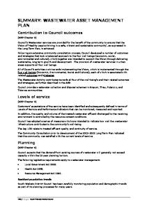
10. Design – Commitment to Bioscrubbers As noted above, in the instance that bioscrubbers become necessary in the future, provision has been made in the layout to add bioscrubbers ahead of the photoionisation units and also to scrub the discharge from the oxidation ditches. A backup bioscrubber would be provided in each group of odour treatment units to achieve the required level of backup and availability. Figures 4 and 5 show the predicted odour contours for Stage 1 of the Alkimos plant with fugitive emissions controlled by covers (as described in previous sections) and the following net odour emission concentrations in the discharge from the stack: • Figure 4 – stack discharge has odour concentration of 2,400 OU • Figure 5 – stack discharge has odour concentration of 4,800 OU. The procedure and wind files used in odour modelling are described in a later section. The predicted odour contours are plotted on a cadastral base map where proposed residential areas are shown in pink, open space is shown in green, commercial areas are shown in blue and the 600 m wide buffer zone for the Alkimos plant is shown in yellow and orange. The existing excavation for the plant is shown as a red polygon. The Stage 1 plant is shown as a series of small red squares in the northern section of the site and the stack as a solid red circle. A 1 km north/east grid is drawn over the base map. It can be seen in Figure 4 that with the lower odour concentration in the stack discharge (2,400 OU), the predicted 5 OU contour (shown as the dotted red line) extends about 300 m from the boundary of the plant, but is well within the buffer zone. It can be seen in Figure 5 that with the higher odour concentration in the stack discharge (4,800 OU), the predicted 5 OU contour (shown as the dotted red line) extends about 500 m from the boundary of the plant, close to the western edge, but still within the buffer zone. Given the uncertainties, the maximum allowable odour concentration in the stack discharge for Stage 1 is set at 4,800 OU. If the odour concentration in the stack discharge exceeds 4,800 OU for an appreciable period (consistently for more than a week), it will mean the odour concentration in the combined flow to the stack (which will mostly be air extracted from the oxidation ditches) is much higher than anticipated. In that event, the Corporation will install odour treatment (eg, bioscrubbers) to scrub the flow from the secondary treatment area. The bioscrubbers will be designed to achieve a discharge odour concentration of less than 4,000 OU for the combined discharge from the stack for 99 % of the time (to provide a factor of safety in regard to the limiting odour concentration of 4,800 OU).
CEE-Ver03-Nov2009
Odour Management Plan for Alkimos Treatment Plant | 19
Figure 4
Predicted Odour Contours- Stage 1 – Stack at 2,400 OU
CEE-Ver03-Nov2009
Odour Management Plan for Alkimos Treatment Plant | 20
Figure 5
Predicted Odour Contours- Stage 1 – Stack at 4,800 OU
CEE-Ver03-Nov2009
Odour Management Plan for Alkimos Treatment Plant | 21
11. Design – Odour Modelling Odour modelling has been carried out to provide a basis to prepare the Odour Management Plan based on the concept designs for the plant. The odour modelling was carried out in accordance with the EPA’s Interim Guidance on Odour as a Relevant Environmental Factor and the Air Quality Modelling Guidance Notes (2006) issued by the DEC. The following procedure was used: • Ausplume Model version 6 as issued by the Victorian EPA; • Odour emission rates as listed in Table 3; • Topography as shown in Figure 6; • 60-minute averaging time; • Meteorological files developed from measurements at the valley site at Alkimos; and • WWTP geometry from concept plans of the existing site. The odour model has been used to predict 99.9 percentile odour contours in the vicinity of the plant. As explained above, the 99.9 percentile predictions represent the odour level that is exceeded for 8 hours per year at each location. Odour emission rates were estimated for the process units based on odour emission measurements made on similar process units at Albany, Beenyup, Broome, Geraldton and Mandurah. The estimates of odour emission rates and the odour emissions from each treatment area are summarised in Table 3. Table 3
Estimated Odour Emissions from Alkimos WWTP
Treatment Unit Inlet Area
Stage 1 odour emission, OU/s
Stage 2 odour emission, OU/s
800
1,000
Secondary Area
5,000
10,000
Sludge Handling
400
500
6,200
11,500
Stack
72,000
140,000
Total for plant
78,500
151,500
Ground level sources
It can be seen that fugitive emissions from the Stage 1 and Stage 2 plants are relatively small. Odour emissions from the stack appear to be relatively large, but it should be recognized that the stack has a large air discharge rate at relatively low odour concentration. Odour modelling will be repeated when the plant has been commissioned and more precise estimates of the odour levels in fugitive emissions and in the stack discharge are available. CEE-Ver03-Nov2009
Odour Management Plan for Alkimos Treatment Plant | 22
There is some uncertainty about the odour level in the air drawn from the oxidation ditch (no measurements could be found of actual odour levels in a comparable situation). Thus it is important that, as part of the commissioning stage, measurements are made of the odour levels in the duct leading from the oxidation ditch and in fugitive emissions, and the modelling repeated. Wind and dispersion conditions for predicting odour levels in the area surrounding the Alkimos plant were based on wind and meteorological measurements at the site. The Water Corporation installed two wind monitoring stations (valley site and hill site) and one meteorological monitoring station at the site and monitoring commenced in 2001 and continued to 2006. The equipment installed at the monitoring station measures: � Wind speed and wind direction at 10 m above the ground; � Air temperature at 2 m and 10 m above the ground; � Solar radiation; and � Sigma theta of wind direction variations. Wind direction, wind speed and air temperature are recorded at 10 minute intervals. The meteorological files were prepared from the wind, temperature and solar radiation measurements using the stability classification criteria published by the Victorian EPA (Plume Calculation Procedure, 1985). The valley wind monitoring site was selected for odour modelling as it was less exposed than the hill wind monitoring site and had lower wind speeds.
12.
Design – Compliance with Odour Criteria
The extent of potential odour nuisance is indicated by the 5 OU contour, where this contour is calculated by the Ausplume model, using a 1-hour averaging period at 99.9 percentile frequency. The Corporation has ascertained that the 5 OU level of odour encompasses the zone of odour complaints from the urban community and also the zone in which odour can be perceived as annoying, based on correlation of odour complaints and odour modelling around the existing Halls Head, Broome, Subiaco, Mandurah, Woodman Point and Beenyup treatment plants. This criterion has recently been endorsed by the EPA in determining an acceptable level of odour for sensitive land uses (EPA Bulletin 1272, October 2007).
CEE-Ver03-Nov2009
Odour Management Plan for Alkimos Treatment Plant | 23
13.
Design – Size of the Stack
The base of the excavation is approximately 11 m above mean sea level. As shown in the topographical map in Figure 6, the land along the western side of the site is at an elevation of 17 to 19 m (6 to 8 m above the base of the excavation). However, land along the northern boundary has an elevation of 21 to 31 m, while the dunes to the east and south of the site reach an elevation of 40 m (about 29 m above the base of the stack). Figure 6
Predicted Odour Contours- Stage 1 – Stack at 4,800 OU
CEE-Ver03-Nov2009
Odour Management Plan for Alkimos Treatment Plant | 24
From the topography map in Figure 6, it can be seen that many of the high dunes are in the buffer zone. Nonetheless, there is land zoned residential that is at 30 to 40 m elevation, particularly to the southeast of the site. Based on the topography, the minimum feasible stack size is a height of 50 m (ie, elevation of top of stack is 61 m). The implications of a higher stack were investigated. Figure 7 shows the predicted odour contours for the Stage 1 plant using a 70 m high stack. There is a reduction in the peak odour contour near the boundary of the buffer zone from 5 OU to 4 OU. Thus there is some benefit from the higher stack. The Corporation has decided that it would be of more benefit to focus attention and expenditure on controlling fugitive emissions rather than construct a higher stack, as available odour treatment units can reduce odour concentrations to a level that can satisfactorily be dispersed through a 50 m high stack. Figure 7
CEE-Ver03-Nov2009
Predicted Odour Contours- Stage 1 – 70 m High Stack
Odour Management Plan for Alkimos Treatment Plant | 25
14.
Design – Sulphur Emission
The photo-ionisation unit is reported to convert approximately 60 per cent of the hydrogen sulphide entering the unit to elemental sulphur that is then discharged through the stack. Thus a model run was carried out to check the implications of the discharge of fine sulphur particles (as S8). The manufacturer advised that the rate of discharge would be 21.3 mg/s. As shown in Figure 8, the predicted ground level concentration of sulphur is less than 0.7 ug/m3, well within acceptable limits for fine particles (25 ug/m3 for PM10). Sulphur is not considered to be a toxic element. Figure 8
CEE-Ver03-Nov2009
Predicted Ground Level Concentration of Sulphur
Odour Management Plan for Alkimos Treatment Plant | 26
15.
Commissioning – Bioscrubber Acclimatisation
As noted above, bioscrubbers are not at present part of the Stage 1 or Stage 2 proposal, but may be installed if there is a need to reduce odour levels. (An alternative odour control technology may be installed if more appropriate). If installed, sufficient bioscrubber units will be provided to allow the design air flow to be scrubbed with one bioscrubber as backup in each scrubber area. This allowance arrangement will allow full scrubbing capacity to be maintained during periods of major maintenance. Any bioscrubbers installed will be acclimatised over a six week period. During this period, the bioscrubbers will be supplied with potable water and a nutrient mix. It was found at Woodman Point that, after six weeks, the bioscrubbers operated efficiently and could remove more than 95 per cent of incoming hydrogen sulphide.
16.
Commissioning – Performance Testing
A key part of the commissioning is to check and verify the performance of the odour control systems. The proposed steps in commissioning are as follows: • Smoke tests under covers to confirm satisfactory degree of sealing. • Measurement of negative pressure and velocity at air intakes to confirm they meet design limits. • Measurement of duct velocities to check satisfactory flow balance and capture of air from covered tanks. • Validation of all measurement equipment. • Monitored performance tests of inlet and outlet odour at odour treatment units to confirm removal efficiency using dynamic olfactometry tests to measure odour level every three days. • Measurement of odour levels in ducts by dynamic olfactometry. • Measurement of fugitive emission rates from covered tanks. • Measurement of odour before and after odour treatment units, duct from oxidation ditches and in stack discharge every three months. • Repeat of odour modelling with actual odour levels.
17. Commissioning – Balancing Duct Flows and Pressures As noted above, the velocities in the duct system must be measured during the commissioning stage to confirm that the design extraction rates from each process unit are being achieved. Some minor increase in extraction rates may be used to achieve the design negative pressures in some areas. The major monitoring parameter for effective odour capture is the records of negative pressure in the various covered areas. CEE-Ver03-Nov2009
Odour Management Plan for Alkimos Treatment Plant | 27
18. Commissioning – Verification of Performance Verification of performance involves five components: 1. Verification of odour capture, as described in Section 16; 2. Verification of odour treatment unit performance as described in Section16; 3. Reports from odour monitors on the boundary of the buffer zone during the commissioning stage, to confirm that odour is not detectible; 4. Conduct phone survey of up to 150 residents living within 1 km of buffer zone every 2 years during Stage 1 operations to ascertain whether odour is detectible and whether odour is a nuisance at times 5. Odour modelling using the actual odour levels measured during the commissioning stage. The responsibility for verification testing and reporting is listed below. Table 4
Verification Testing and Reporting - Alkimos WWTP
Verification Step
19.
Responsibility
Smoke tests under covers
Installation contractor
Negative pressure- tests
Installation contractor
Negative pressure - monitoring
Operations
Scrubber performance test
Scrubber supplier
Measure fugitive emissions
Installation contractor
Measure odour in ducts
Odour audit
Update odour modelling
Odour audit
Report on verification
Odour audit
Operations – Standard Operating Procedures
Standard operating procedures are established to ensure that the odour control system continues to operate effectively during the service life of the system, under all normal and abnormal operating conditions. Standard operating procedures set out the steps to be followed in operating and maintaining the plant, including the following aspects: • Daily check (week days) of odour treatment unit conditions including manual test of discharge H2S concentration at entry to and exit from odour treatment units; • Daily check (week days) of negative pressures under covers; • Procedures for responding to odour treatment unit alarms; • Procedures for maintaining odour treatment units; CEE-Ver03-Nov2009
Odour Management Plan for Alkimos Treatment Plant | 28
• • • •
Procedures for cleaning and washing process tanks before covers are removed with minimal release of odour; Procedures for maintaining and removing mechanical equipment with minimal release of odour; Monthly reporting on performance of odour control system. Plan maintenance to avoid long shut-downs of equipment. Advise regulatory authority and local residents of major maintenance on the plant when the plant will be out of operation.
20. Operations – Replacement of Scrubber Media Bioscrubber media is considered to have a service life of 15 years. Thus when media needs to be replaced, it will be done one vessel at a time. During such periods, there will be no standby unit, so media replacement should be programmed where feasible for winter when odour inputs to the plant are lower. Activated carbon media is considered to have a service life of 5 years. Thus media replacement occurs more frequently but using the same procedure of replacing media one unit at a time, and keeping full treatment capacity in the other operating units. The service life of UV lamps is expected to be about 2 years. Lamps may be removed and replaced quickly, so this should not be an operation that has an impact on the performance of the odour treatment system.
21. Monitoring – Regular Odour Monitoring The following odour monitoring will be carried out: • Continuous H2S monitoring at the entry to all odour treatment systems (and between different types of odour treatment units in the event that bioscrubbers are installed); • Continuous H2S monitoring at the discharge from all odour treatment systems; • Continuous H2S monitoring at the entry to the stack; • Manual verification of H2S each fortnight at the entry to the odour treatment units and the entry to the stack. • Collect odour samples at five nominated sampling points (before and after odour treatment units) monthly for the six months of operation after commissioning and each quarter thereafter and analyse in NATA registered laboratory. As noted above, a phone survey of up to 150 local residents living within 1 km of buffer zone will be carried out every 2 years during the Stage 1 operation of the plant to seek further evidence as to whether or not there is a noticeable odour beyond the plant buffer zone.
CEE-Ver03-Nov2009
Odour Management Plan for Alkimos Treatment Plant | 29
22. Monitoring – Complaint Registration and Response The Water Corporation will maintain a 24-hour phone line to allow any member of the public to report an odour complaint at any time. The following information is recorded for each complaint: • Date and time of complaint; • Concern expressed by person complaining; • Address, time and duration of odour; • Whether experienced at other times; • Character of odour. Within 1 working day, complaints are sent to the duty operator or treatment plant manager for investigation. The investigation considers the types of operations and maintenance at the plant at the time, wind speed and direction at the plant and other factors that may have caused or exacerbated the concern. A report on the complaint is stored. The person making the complaint will be phoned (unless they ask not to be contacted) to advise that the complaint is being investigated and the findings to date.
23. Contingency Plans for Upsets or Maintenance The Standard Operating Procedures will set out the steps to be followed in the event of upsets or major maintenance. The target will be to keep the odour treatment systems operating effectively for 99.9 % of the year (excluding external events such as power failures). This should be seen as a goal and not as a mandatory target. As noted above, replacement of media is a relatively infrequent event. From experience with odour control systems at other plants, the major types of upsets are: • Power failures; • Failures of mechanical equipment, such as dosing pumps; • Failures of the computer control system. All failures will automatically trigger alarms and operators are available on a 24-hour basis to take remedial action. The most common types of remedial actions are: • Re-start following power or equipment failure; • Replace equipment with standby equipment; • Bypass some unit and operate remaining odour treatment units at a slightly lower rate with remaining odour treatment units.
CEE-Ver03-Nov2009
Odour Management Plan for Alkimos Treatment Plant | 30
24.
Contingency Plans in the Event of Exceedances
The Water Corporation will include in the operations procedures a contingency plan to investigate and resolve events and periods with high odour levels. A period with high odour levels is taken to occur if there are 3 or more odour complaints from two or more residents about odour in a 3 month period, or the phone survey shows that more than 10 % of the nearby community perceive odours coming from the Alkimos plant at an uncomfortable level. The protocol to follow in the contingency plan is set out below.
ODOUR NUISANCE DETECTED
Investigate and identify odour sources
Excessive fugitive odour emissions
High odour from scrubbers
1. Ensure covers kept closed 2. Ensure negative pressure achieved 3. Check no major source uncontrolled
Repair or replace scrubbers No action needed
Confirm actions completed
Trigger odour audit
Monitor to confirm compliance
CEE-Ver03-Nov2009
Odour from other sources (eg. Seaweed)
Odour Management Plan for Alkimos Treatment Plant | 31
25.
Reporting and Re-design as Required
An annual report will be prepared on the performance of the plant, including the odour control system. There will be an odour audit every two years of the Stage 1 operation to establish the effectiveness of the odour control system, the performance of odour treatment units, the level of odour coming from the oxidation ditches, response of the public (as reported by odour complaints or community surveys) and any remedial actions required. The annual report and odour audits will provide the information needed to select and optimise the design of future odour control technologies in later stages of the Alkimos WWTP.
CEE-Ver03-Nov2009
Odour Management Plan for Alkimos Treatment Plant | 32
26. Summary of Odour Management Plan The procedures required to implement this Odour Management Plan are summarised below. This summary is for reference only; the preceding sections provide a fuller description and take precedence. Table 5 Alkimos Odour Management Plan: Summary of Required Procedures Aspect to be addressed
Required Procedure Design
A Preliminary treatment area All tanks and channels to be fully covered with Appropriate corrosionA1 resistant covers specifically designed to capture odours A2 Seals for covers to have flexible gaskets at least 30 mm wide A3 Covers to be bolted at close spacing to achieve an air-tight seal A4 All equipment and bins to be fully sealed with ducts to remove foul air Air extraction rates for tanks and equipment to meet Water A5 Corporation best practice guidelines (12 to 45 air changes/hour) Negative pressure sensors in tanks and ducts, connected to SCADA A6 system. Design negative pressure of – 15 Pa or better A7 Sufficient duct connection points on each tank to avoid dead zones Measurement and monitoring points and equipment to be provided on ducts and before and after odour treatment unit. Standard A8 measurement station just before stack. Condensate drainage and monitoring points installed on ducts B Secondary treatment area All oxidation ditch tanks and channels to be fully covered with B9 Appropriate corrosion-resistant covers specifically designed to capture odours B10 Seals for covers to have flexible gaskets least 30 mm wide B11 Covers to be bolted at close spacing to achieve an air-tight seal B12 Velocity at air inlets to be 1.5 m/s or more Air extraction rate to be capable of 30,000 m3/hr from each of the B13 Stage 1 oxidation ditches Negative pressure sensors in tanks, connected to SCADA system. B14 Design negative pressure of – 15 Pa or better B15 Sufficient duct connection points on each tank to avoid dead zones B16 Measurement and monitoring points and equipment installed on ducts No air path between ditches, so that any ditch can be taken out of B17 service for maintenance without affecting odour capture
CEE-Ver03-Nov2009
Odour Management Plan for Alkimos Treatment Plant | 33
Aspect to be addressed
Required Procedure Design
C Sludge area All tanks to be fully covered with appropriate corrosion-resistant covers specifically designed to capture odours C19 Seals for covers to have flexible gaskets least 30 mm wide C20 Covers to be bolted at close spacing to achieve an air-tight seal Negative pressure sensors in sludge storage and DAF tanks C21 connected to the SCADA system. Design negative pressure of – 15 Pa or better Air extraction rates for tanks and equipment in accordance with Water C22 Corporation best practice guidelines C23 Sufficient duct connection points on each tank to avoid dead zones C24 Measurement and monitoring points and equipment installed on ducts D Odour treatment units D25 All air extracted to be treated, with no bypassing Discharge odour from photo-ionisation unit to be less than 800 OU for D26 99 % of the time Redundancy to be provided, with a target availability for the odour D27 treatment unit system of 99.9 % of the year (including a backup bioscrubber if installed) Major maintenance to be carried out on non-operating unit with D28 remaining units operating Continuous measurement of H2S before and after odour treatment D29 units with SCADA logging of results Continuous measurement of air flow rate and temperature before and D30 after odour treatment units Measurement of odour before and after odour treatment units, and in D31 oxidation ditch duct and stack discharge every three months Measurement and monitoring points installed on ducts for manual D32 sampling, and flow measurement and balancing E Bioscrubbers Install odour treatment (eg, bioscrubber) if odour concentration in air E33 discharged from stack exceeds 4,800 OU Allow six week acclimatisation period for any bioscrubbers with supply E34 of water and nutrients C18
CEE-Ver03-Nov2009
Odour Management Plan for Alkimos Treatment Plant | 34
Aspect to be addressed
Required Procedure Commissioning
F Checking performance F35 Smoke tests under covers to confirm satisfactory degree of sealing Measurement of negative pressure and velocity at air intakes to F36 confirm they meet design limits Measurement of duct velocities to check satisfactory flow balance and F37 capture of air from covered tanks F38 Validation of all measurement equipment Monitored performance tests of inlet and outlet odour at odour F39 treatment units to confirm removal efficiency – odour measured every three days using dynamic olfactometry F40 Measurement of odour levels in ducts using dynamic olfactometry F41 Measurement of fugitive emission rates from covered tanks Measurement of odour before and after odour treatment units, duct F42 from oxidation ditches and in stack discharge every three months F43 Repeat of odour modelling with actual odour levels G Verification of performance Refer to Table 4 for allocation of responsibilities for verification tasks G44 Verification of odour capture, as described in Section 16 Verification of odour treatment unit performance as described in G45 Section 16 Reports from odour monitors on the boundary of the buffer zone G46 during the commissioning stage, to confirm that odour is not detectible Conduct phone survey of up to 150 residents living within 1 km of G47 buffer zone every 2 years during Stage 1 operations to ascertain whether odour is detectible and whether odour is a nuisance at times Odour modelling using the actual odour levels measured during the G48 commissioning stage Operations H Operations and maintenance Develop Standard Operating Procedures for operation and maintenance of covered tanks, duct and fan systems and odour treatment unit systems. Procedures to include: Daily check of odour treatment unit conditions including manual test of discharge H2S concentration at entry to and exit from odour treatment units • Daily check of negative pressures under covers (week days) • Procedures for responding to odour treatment unit alarms • Procedures for maintaining odour treatment units H49 • Procedures for cleaning and washing process tanks before covers are removed with minimal release of odour • Procedures for maintaining and removing mechanical equipment with minimal release of odour • Monthly reporting on performance of odour control system • Plan maintenance to avoid long shut-downs of equipment • Advise regulatory authority and local residents of major maintenance on the plant when the plant will be out of operation CEE-Ver03-Nov2009
Odour Management Plan for Alkimos Treatment Plant | 35
Aspect to be addressed H50
H51 H52
Required Procedure Replace bioscrubber when needed one vessel at a time. Media replacement should be programmed where feasible for winter when odour inputs to the plant are lower Replace activated carbon media when necessary. Replace media one unit at a time, keeping full treatment capacity in the other operating units Replace UV lamps as necessary ensuring this operation does not impact on the performance of the odour treatment system
I Monitoring I53 I54 I55 I56
I57
I58
I59
I60
Continuous H2S monitoring at the entry to all odour treatment systems (and between different types of odour treatment units in the event that bioscrubbers are installed) Continuous H2S monitoring at the discharge from all odour treatment unit systems Continuous H2S monitoring at the entry to the stack Manual verification of H2S each fortnight at the entry to the odour treatment units and the entry to the stack Collect odour samples at five nominated sampling points (before and after odour treatment units) monthly for the six months of operation after commissioning and each quarter thereafter and analyse in NATA registered laboratory Conduct phone survey of up to 150 local residents every 2 years during the Stage 1 operation of the plant to seek further evidence as to whether or not there is noticeable odour beyond the plant buffer zone Maintain a 24-hour phone line to allow any member of the public to report an odour complaint at any time. Record the following information for each complaint: • Date and time of complaint • Concern expressed by person complaining • Address, time and duration of odour • Whether odour noticed at other times • Character of odour Within 1 working day, send complaints to the duty operator or treatment plant manager for investigation. Contact the person making the complaint (unless they ask not to be contacted) to advise that the complaint is being investigated and the findings to date
CEE-Ver03-Nov2009
Odour Management Plan for Alkimos Treatment Plant | 36
Aspect to be addressed
Required Procedure Contingency Plan
J Contingency plan Establish Standard Operating Procedures to be followed in the event J61 of upsets or major maintenance. The target will be to keep the odour treatment systems operating effectively for 99.9 % of the year Provide alarms to identify failures of equipment and systems. Ensure J62 operators monitor alarms and personnel are available on a 24-hour basis to take remedial action Include in the operations procedures a contingency plan to investigate J63 and resolve events and periods with high odour levels Establish a protocol to follow to resolve high odour levels as part of the J64 contingency plan (see Section 24). Prepare an annual report on the performance of the plant, including J65 the odour control system Conduct an odour audit every two years of the Stage 1 operation to establish the effectiveness of the odour control system, the J66 performance of odour treatment units, the level of odour coming from the oxidation ditches, the response of the public (as reported by odour complaints or community surveys) and any remedial actions required
CEE-Ver03-Nov2009