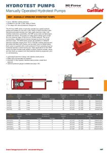
Volute pumps ZDN 32 - 160 ... 65 - 200 ZHN 32 - 160 ... 65 - 200
TECHNICAL DATA Output:
max. 200 m³/h
Delivery head:
max. 60 m
Speed:
max. 3600 1/min
Medium temperature:
ZDN max. 185 °C ZHN max. 180 °C
Casing pressure:
ZDN PN 25 ZHN PN 16
Shaft sealing:
standard mechanical seal uncooled
Flange connections:
ZDN DIN 2501 PN 25 ZHN DIN 2501 PN 16
Sense of rotation:
clockwise, when seen from the drive on the pump
APPLICATION
CONSTRUCTION
The volute pumps of the series ZDH / ZHN are part of the general programme of heat transfer and circutation pumps. They are primarily used for circulation of hot water in closed pipe and vessel systems.
Casing pressure
Therefore their fields of application are energy production, heat transport and industry and here mainly in systems where hot water as heat carrier is given preference, despite its high system pressure, over oil as heat carrier.
ZDN: max 25 bar from - 30 °C to + 185 °C ZHN: max 16 bar from - 30 °C to + 120 °C max 14 bar from + 120 °C to +180 °C Please note: casing pressure = inlet pressure + zero head max test pressure = ZDN 33 bar; ZHN 21 bar
Position of branches: Suction branch axially, discharge branch radially pointing upwards.
Flanges: ZDN: The flanges correspond to DIN 2534/PN 25. Flange design ANSI 300 is possible. ZHN: The flanges correspond to DIN 2533/PN 16. Flange design ANSI 150/300 is possible.
Hydraulics: First Hydraulics. Code of this design: A./C. Second Hydraulics. Code of this design: B.
DESIGN ZDN: Horizontal, single-stage volute pumps with connections to DIN 24 256 / EN 22 858 in back pull out design. ZHN: Horizontal, single-stage volute pumps with connections and main dimensions to DIN 24255 / EN 733 in back pull out design. The series ZDN / ZHN is especially designed for troublefree pumping of hot water; up to 185 °C, with uncooled mechanical seals. The pumps have the following remarkable features: • by a special conception gas accumulations in the mechanical seal chamber are pumped independently to the ventilation. Thus a dry operation of the mechanical seal is excluded. • the back pull out design allows the disassembly of the complete bearing unit towards the drive side so that it is not necessary to detach the pump casing out of the pipe system. If a spacer type coupling is used also the loosening of the motor becomes superfluous
133.64801.52.01 E
Bearing: One grease-lubricated antifriction bearing to DIN 625 and one liquid-surrounded sleeve bearing. Code of this design: .A
Sense of rotation: Clockwise, when seen from the drive on the pump.
Shaft sealing: The shaft is sealed by an internally flushed, uncooled standard mechanical seal. Code B27: sliding material WC/carbon for hot water without abrasive admixtures temperature range up to 185 °C pressure range up to 25 bar Code BJ3: sliding material SiC/carbon for hot water without abrasive admixtures temperature range up to 180 °C pressure range up to 16 bar Other shaft seals upon request.
PUMPTECHNOLOGY ZDN/ZHN P I / 40 07/98
Material design:
Item
COMPONENTS
METERIAL DESIGN 1B
10.20
volute casing
16.10
casing cover
21.00
shaft
23.00
impeller
33.00
bearing carrier
43.30
shaft seal
44.10
casing for mechanical seal
52.90 / 54.00
GGG 40.3
X 20 Cr 13 GG 25 GGG 40.3 WC / carbon resp. SiC / carbon
sleeve bearing
GG 25 SiC
Casing seal: The casing is sealed by a coated flat seal of special graphite. Code of this design: 2
Drive / speed: By commercial electric motors, type of construction IM B3. For the determination of the drive power we recommend the following additions: up to 4 kW: 25% 4 to 7,5 kW: 20%
to 7,5 kW: 15%
The following speeds are to be observed: max. speed
size
rpm 32-160 40-160 50-160 65-160 80-160
3600
32-200 40-200 50-200 65-200
General comments: For equipping heat transfer plants, which are operated with hot water, a complete programme of additional series is available for an output range up to 1200 m3/h: series ZLN
volute pumps to DIN 24255/EN 733, tmax 160 °C
series ZEN
volute pumps to DIN 24256/EN 22858, tmax 230 °C PN 40
series ZLI
PN 25 hot water design, volute pump on the basis of DIN 24255/EN 733 as INLINE-construction, tmax 150 °C
series ZTN
design with base plate tmax 350 °C for heat transfer oil.
Pumps for heating / cooling operation on request. Technical documentation on these programmes will be supplied on request.
2
Sectional drawing and nomenclature
10.20 16.10 21.00
volute casing casing cover shaft
23.00 33.00 43.30
impeller bearing bracket shaft seal
44.10 casing for mechanical seal 52.90/54.00 sleeve bearing
Heat barrier / shaft seal / bearing / feet arrangement Heat transfer plants have reached a high technical standard. Consequently the demands on the pumps for handling heat carriers have increased regarding operating reliability, environmental protection, maintenance and operating costs. On the basis of many years’ experience and latest technical know-how the ZDN/ZHN fully meets these demands. The temperature reduction makes it possible to use safely an uncooled mechanical seal up to a pumping medium temperature 185 °C resp. 180 °C.
Curve of temperature decrease
3
Performance graph
n = 2900 rpm
Performance graph
n = 1450 rpm
4
Characteristic curves
n = 2900 rpm
only ZDN
5
Characteristic curves only ZHN
6
n = 2900 rpm
Characteristic curves
n = 2900 rpm
Characteristic curves
n = 1450 rpm
7
Characteristic curves
n = 1450 rpm only ZDN
8
Characteristic curves
n = 1450 rpm
Values are valid for water ρ = 1kg/l
9
Dimension table ZDN
UL = vent valve
size
DNA
DNE
32
50
32-160 32-200
a
b
c
f
80
40-160
40
65
50
h1
h2
132
160
160
180
132
160
40-200
100
m2
n1
n2
240
190
50
17
80
50-200
360
65
80-160
80
265
100 125
180
225
125
125
95
w2
x
120
100
140
140
320
14
260
135
flange design to ANSI 300 is possible DNA/DNE
32
40
50
65
80
100
125
D
140
154
165
190
208
254
280
k
100
110
125
145
160
190
220
d2 x number
18x4
18x4
18x4
18x8
18x8
22x8
26x8
100
160 155
250
175 170
flange connections to DIN 2501 PN 25/40
d1
l
t
u
24
50
27
8
150 15
212
200 65
w1
125
280
65-200
s2
219
160
100
65-160
s1
70
180
50-160
10
m1
140
Dimension table ZHN
UL = vent valve
size 32-160
DNA
DNE
32
50
32-200 40-160
40
f
h1
h2
132
160
160
180
132
160
15
50
360
n2
s1
s2
w1
240 100
190
125
d1
l
t
u
24
50
27
8
120 140 265
225
x
137
70
212
15
14
267
80
130 150
280 180
w2 120
80 100
n1
200 65
80
m2
160
100 65
m1
180
65
65-200 80-160
c
50
50-200 65-160
b
80
40-200 50-160
a
125
95
320
147 250
165
100
163
flange connections to DIN 2501 PN 16 DNA/DNE
32
40
50
65
80
100
D
140
150
165
185
200
220
k
100
110
125
145
160
180
d2 x Anzahl
18x4
18x4
18x4
18x4
18x8
18x8
11
Foundation plan ZDN
minimum length of rag bolt
dimensions in mm, design tolerances (base plates) for castings to DIN 1686/GTB 17, for welded parts to DIN 8570 B motor size
32-160
32-200
40-160
40-200
50-160
50-200
65-160
65-200
80-160
size
kW
80b 90S 90L 100L 112M 90L 100L 112M 132S 132M 90S 90L 100L 112M 132S 112M 132S 132M 160M 160M 90L 100L 112M 132S 132M 160M 100L 112M 132S 132M 160M 160M 132S 132M 160M 160M 160M 160M 160L 180M 200L 132M 160M 160M 160L 180M
1,1 1,5 2,2 3,0 4,0 2,2 3,0 4,0 5,5 7,5 1,5 2,2 3,0 4,0 5,5 4,0 5,5 7,5 11,0 15,0 2,2 3,0 4,0 5,5 7,5 11,0 3,0 4,0 5,5 7,5 11,0 15,0 5,5 7,5 11,0 15,0 11,0 15,0 18,5 22,0 30,0 7,5 11,0 15,0 18,5 22,0
base plate No.
coup-
P 241
A 10
P 272
ling
A 10
P 272
A 25
P 303 P 241
weight pump **kg
52
A 25
P 241
60
A 63 A 10 52
P 272 P 272
A 25 A 63 A 25
P 303
A 63
54
P 344 P 301
A 10
P 272
A 25
P 303 P 344 P 272
A 63 55 A 10 A 25
P 303 P 344 P 303
A 63
68
P 344 70 P 385
A100 A160
P 344
A 63
P 385
A100
73
unit kg
82 85 88 97 102 96 105 110 136 153 87 90 98 117 130 119 132 135 208 210 98 101 120 133 136 219 101 120 157 160 209 211 170 173 259 261 261 263 287 314 419 215 264 266 290 317
a
b2
c
330
e1
e2
e4
480
290
115
f1
h
h3
l
p1
80
320
130
800
330
480
290
115
710
540
320
130
225
390
600 480
330
350 290
65
150 115
800
540
320
900 710
130
42
390 450
30
390 360
100
25
600
350
150
660
400
170
480
350
115
540
320
130
225 80
240
1000
65
225
350 400
150 170
80
240
900 1000
360
25
540
320
130
65
225
800
450 390
30 25
150
660
400
170
600
350
70 60 48
800
600 660
350
-
710
30
600
28
900
390 450
390
32 20 48
800 60
28 60 48 28
900 80
150
65
240 225
900
660
400
170
w1
820 730 820 M 16x200 920 730
820
920
782 730 826 843 820 G « 905 943 920 1046 1020 826 843 820 905 943 920 1046
28
905 943
740
440
190
1046
1000
80
1120 260
125
M 20x200
M 16x200
M 20x200 M 16x200
1020 920
-
75 30
rag bolt DIN 529
730
1020
20 490
ue
1046 1020
1000
240 450
710 737 762 806 823 762 806 823 885 923 737 762 806 823 885 843 905 943
28
197 360
52
32 20 70 60 48
540
25
w*
42
360
360
p2
710 197
20 48
450
660
400
170
1000
490
740
440
190
1120
* Motors type of enclosure IP 54, dimensions dependant on motor make. **Weight higher by 20% in case of cast steel
12
n = 2900 rpm
-
20 -
1090 1113 1140 1201 968 1071 1020 1115 1138 1140
M 20x200
Foundation plan ZHN
minimum length of rag bolt
dimensions in mm, design tolerances (base plates) for castings to DIN 1686/GTB 17, for welded parts to DIN 8570 B motor
size
32-160
32-200
40-160
40-200
50-160
50-200
65-160
65-200
80-160
size
kW
80b 90S 90L 100L 112M 90L 100L 112M 132S 132S 90S 90L 100L 112M 132S 100L 112M 132S 132S 160M 90L 100L 112M 132S 132S 160M 100L 112M 132S 132S 160M 160M 132S 132S 160M 160M 160M 160M 160L 180M 200L 132S 160M 160M 160L 180M
1,1 1,5 2,2 3,0 4,0 2,2 3,0 4,0 5,5 7,5 1,5 2,2 3,0 4,0 5,5 3,0 4,0 5,5 7,5 11,0 2,2 3,0 4,0 5,5 7,5 11,0 3,0 4,0 5,5 7,5 11,0 15,0 5,5 7,5 11,0 15,0 11,0 15,0 18,5 22,0 30,0 7,5 11,0 15,0 18,5 22,0
base plate No.
coup-
P 241
A 10
P 272 P 241 P 272 P 303 P 241
-ling
weight pump **kg
49
A 25 A 10 A 25
54
A 63 A 10 43
P 272
A 25 A 63 A 10 A 25 45 A 63
P 344 P 301
A 10
P 272
A 25
P 303 P 344
A 63
P 272
A 10 A 25
P342
47
45
P 344 P 303
A 63
53
P 344 52 S 385
A100 A160
P 342 P 344 S 385
A 63 A100
n = 2900 rpm
54
unit kg
82 86 90 100 118 95 105 123 141 144 80 84 94 112 129 96 114 132 135 209 93 98 116 134 137 211 97 115 144 147 209 211 151 154 217 219 217 219 242 301 397 159 218 220 243 302
a
80
b2
e1
e2
e4
330
480
290
115
360
540
320
330
480
290
360
c
25
330
540
320
f1
h
h3
l
p1
290
320
30
660 480
25
540
400 350
30
826
820
115
710
767
730
28
909
710
42
748 767 826
800
32 20 60
225
130
115
130
80
170 115
65
130
660
170
540
130
25 100 450
800
660 390
240
1000 710
225
800
-
25
600
80
240
65
225
80
130
65
490
30
40
660
740
400
440
540 125
450
30
490
40
660 740
170
190
75
225
80
440
170 190
826
820
929
-
900
28
G½
929
846
M 20x200
820
M 16x200
920 1094 1020 846 820
M 20x200
929
290
80
260
110
290
1094 1020 929
920
1094
1000
310
130 400
909
28
1000
260 110
M 16x200 730
240
240 450
820
1094 1020 787 730
60 48
ue
826
48 28 70 60 48
28 170
350
1000 800
400
30
730
32 20 70 60 48
320
360
702 742 767
800
225 450 390
52
130
197
197
540
w1
42
60 360
w*
710
65 480
p2
rag bolt DIN 529
M 16x200 G¼
1020
20 1120
20
800 1000 1120
48
-
20 -
1138 1165 1263 954 1119 1163 1190
-
-
M 20x200
820 1020 -
G½ -
* Motors type of enclosure IP 54, dimensions dependant on motor make. **Weight higher by 20% in case of cast steel
13
Foundation plan ZDN
minimum length of rag bolt
dimensions in mm, design tolerances (base plates) for castings to DIN 1686/GTB 17, for welded parts to DIN 8570 B motor
size
size
kW
32-160
71b 80a 80a 80b 90S 71b 80a 80b 90S 80b 90S 90L 80a 80b 90S 80b 90S 90L 100L 80b 90S 90L 100L 90S 90L 100L 100L 112M 80b 90S 90L 100L 100L
0,37 0,55 0,55 0,75 1,1 0,37 0,55 0,75 1,1 0,75 1,1 1,5 0,55 0,75 1,1 0,75 1,1 1,5 2,2 0,75 1,1 1,5 2,2 1,1 1,5 2,2 3,0 4,0 0,75 1,1 1,5 2,2 3,0
32-200
40-160
40-200
50-160
50-200
65-160
65-200
80-160
base plate
coup-
No.
-ling
weight pump **kg
52 60 P 241 A 10
52
54
P 301 55
P 272 P301 P 303
A 25 A 10
68
A 25 A 10 A 25
P 383
70
A 63 A 10 73 A 25
unit kg 80 81 89 91 93 79 82 84 87 91 94 97 90 92 95 92 95 98 101 115 118 121 125 130 133 137 140 157 130 133 136 140 143
a
80
b2
c
e1
330
e2
e4
f1
h
290
480
h3
l
p1
197
115
710 60
25 390
p2
w*
61
676
52
712
42 61
734 676
52
712
42 80
734 732 759 784
70
65 350 225
100
80
732
70 80
759 732 759 784 850 729 756 781 825 756 781
70 360
540
320
480 390
130
800
115
710
350
60 80 70 60 90
150 30
75
600
490 125
* Motors type of enclosure IP 54, dimensions dependant on motor make. **Weight higher by 20% in case of cast steel
14
n = 1450 rpm
900 440
80
260
80
825
68 100
842 754 781 806
90 80
850
w1
ue
rag bolt DIN 529
730 M 16x200
G«
820 730
920 M 20x200
Fundamentplan ZHN
minimum length of rag bolt
dimensions in mm, design tolerances (base plates) for castings to DIN 1686/GTB 17, for welded parts to DIN 8570 B motor size
32-160 32-200
40-160
40-200
50-160
50-200
65-160
65-200
80-160
size
kW
71b 80a 80a 80b 90S 71b 80a 80b 90S 80a 80b 90S 90L 80a 80b 90S 80b 90S 90L 100L 90b 90S 90L 100L 90S 90L 100L 100L 112M 80b 90S 90L 100L 100L
0,37 0,55 0,55 0,75 1,1 0,37 0,55 0,75 1,1 0,55 0,75 1,1 1,5 0,55 0,75 1,1 0,75 1,1 1,5 2,2 0,75 1,1 1,5 2,2 1,1 1,5 2,2 3,0 4,0 0,75 1,1 1,5 2,2 3,0
base plate
coup-
No.
-ling
weight pump **kg
49 54 P 241 43 A 10 45
P 301
47
45 P 272
A 25
P 301
A 10
P 303
53
A 25 A 10 A 25
P 342
52
A 63 A 10 54 A 25
n = 1450 rpm
unit kg 78 81 86 87 90 75 75 76 80 82 83 87 91 84 85 89 84 87 91 97 91 95 99 106 109 113 120 121 130 107 111 115 122 125
a
b2
c
e1
e2
e4
f1
h
h3
l
p1
197 225 80
330
290
p2
w*
61
678
52 80
687
70 61 197
480
52 42
710
80 115
60
25
70
65
390
350
80 225
100
70 80 70
360
540
320
800
60 80
390
480
350
710
70
900
60
600
150
90 75
80 800
450
30
540
125
400
130
80
260
68 100
702 742 676 687 702 742 707 722 762 787 707 722 762 722 762 787 846 722 762 787 846 762 787
w1
ue
rag bolt DIN 529
730
M 16x200
G«
820 730 920
846
90
747 787 812
80
871
820
M 20x200
* Motors type of enclosure IP 54, dimensions dependant on motor make. **Weight higher by 20% in case of cast steel
15
Data regarding size - order hints series+ size
hydraulic + bearing A./ C. hydraulic A B. hydraulic B .A
ZDN
ZHN
32-160 32-200 40-160 40-200 50-160 50-200 65-160 65-200 80-160 32-160 32-200 40-160 40-200 50-160 50-200 65-160 65-200 80-160
1 greased antifriction bearing and 1 liquid-surrounded sleeve bearing
shaft seal
B27 BJ3
material design
balanced standard mechanical seal WC/ carbon
1B
casing seal
main parts of nobular cast iron
2
flat seals
standard mechanical seal SiC / carbon
AA BA CA
B27
AA 1B
2
AA AA CA
BJ3
AA
motor selection table design
code
pump with free shaft end
01
pump with coupling, motor side predrilled
04
as before, but pump mounted on base plate
05
as before, but with motor and contact safety device for shaft coupling, for example 30 kW three-phase AC motor (50 Hz, 380 V) 2900 rpm
e.g. XA
motor n=2900 rpm kW 1,1 1,5 2,2 3,0 4,0 5,5 7,5 11 15 18,5 22 30
size 80 b 90 S 90 L 100 L 112 M 132 S 132 S 160 M 160 M 160 L 180 M 200 L
motor n=1450 rpm code GA HA JA KA MA NA OA SA TA UA VA XA
Example for ordering: The size ZDN 65-200 AA B27 1B 2 with coupling, motor side predrilled has the complete order number: The size ZDN 65-200 AA B27 1B 2 as complete unit with 30 kW three-phase AC motor, 2900 rpm has the complete order number:
kW 0,37 0,55 0,75 1,1 1,5 2,2 3,0 4,0
size 71 b 80 a 80 b 90 S 90 L 100 L 100 L 112 M
code EB FB GB HB JB KB LB MB
ZDN .65-200 AA B27 1B 2 04 ZDN .65-200 AA B27 1B 2 XA
On delivery the point ( . ) as the fourth place of the type designation is replaced in the factory by a letter. If we are informed of the motor type being selected, the coupling can be ready drilled on motor side, and we can supply the contact safety device for the coupling and the shims for equalizing out the center height. Any changes in the interest of the technical development are reserved.
Sterling SIHI GmbH Lindenstraße 170 , D-25524 Itzehoe, Germany , Telephone +49 (0)48 21 / 7 71-01 , Telefax+49 (0)48 21 / 7 71-274
16