2015 IEEE/SICE International Symposium on System Integration (SII) December 11-13, 2015. Meijo University, Nagoya, Japan
Visual-servo-based Autonomous Docking System for Underwater Vehicle Using Dual-eyes Camera 3D-Pose Tracking Myo Myint∗1 , Kenta YONEMORI∗2 , Akira YANOU∗3 , Mamoru MINAMI∗4 , Shintaro ISHIYAMA∗5 Nowadays, research on the docking system using various homing sensors and techniques for the underwater robot has been done worldwide [6]-[14]. Normally, different combination of sensors are used in homing unit to get information for docking operation. The optical terminal guidance technique was introduced in [6]. A docking guidance system was designed and implemented using the Sugeno fuzzy inference system (FIS) in [7]. Electromagnetic Homing (EM) system was proposed and tested in [8] for docking experiments. In [9], the AUV homes to the dock using an ultrashort base line (USBL) sonar transceiver mounted in the vehicle nose. In this work, dual-eyes camera is used for visual-servo in docking experiment rather than using combination of other sensors. In this paper, we have developed a visual servoing system that recognizes the relative pose between ROV and target object utilizing Genetic Algorithm using images from dualeyes cameras mounted in the ROV. We conducted regulated performance experiments on the relative pose control between the ROV and 3D target. When ROV, which has been partially automated by visual servo, is required to carry out various activities (such as automatic charging, Raw fish capture [5] etc.) under bottom of sea, lake and pond, the exact recognition of environment at the bottom of sea and robustness against disturbance existing in recognition process through cameras set on the AUV are important. It is shown experimentally that the proposed system is stable to physical disturbances given by external forces to the ROV. Finally, docking experiment underwater automatic charging is implemented using proposed system, having approved its robustness against disturbances and its usefulness.
Abstract— A visual-servo type remotely operated vehicle (ROV) system with binocular wide-angle lens was developed to survey submarine resources, decontaminate radiation from mud in dam lake and so on. This paper explores the experiments on regulator performance and underwater docking of the robot system utilizing Genetic Algorithm (GA) for real-time recognition of the robot’s relative pose (position and posture) through 3D marker. The visual servoing performances have been verified as follows; (1) The stability performances of the proposed regulator system have been evaluated by exerting abrupt distrubane force while the ROV is controlled by visual servoing, (2) The proposed system can track time-variant desired target position in z-axis (front-back direction of the robot), (3) The underwater docking can be completed by switching visual servoing and docking modes based on the error threshold, and by giving time-varying desired target pose to the controller as a desired pose.
I. INTRODUCTION After the Tohoku Earthquake on March 11 2011, Fukushima prefecture has been afflicted by disasters like earthquake, tsunami and nuclear power accident, then decontamination work has been proceeding in radioactive contamination area. Moreover, the issue of radioactive contamination of the underwater mud in rivers and reservoirs has been highlighted as a serious problem in reconstruction for agriculture in Fukushima Prefecture. However, it is too difficult to do decontamination recovery operations in underwater such as 100 [m] depth because of the less work ability situation from radiation shielding effect and water current. Therefore, we have been developing visual servoing system for AUV (Autonomous Underwater Vehicle) by mounting 3D pose controller composed of binocular camera in the underwater vehicle for the purpose of automatic recovery of deep water of radioactive contamination bottom mud. It is expected to have the following functions: (1) Automatic recognition of a target object, (2) Autonomous navigation, (3) Consecutive decontamination work for a long time, (4) Accurate radioactive measurement, (5) Automatic recharging the batteries equipped in the AUV, (6) Investigation and analysis of water environment (temperature, concentration, flow rate, etc.) by sensors. There are some works done by authors on visual-servo experiments concerning handeye manipulator in the air using 3D Model-based matching method utilizing Genetic Algorithms and dual-eyes camera [1]-[3], which are used as fundamental knowledge for this research.
II. P ROPOSED S YSTEM Apart from some works considering the dynamic model, the proposed system estimates relative pose through 3D model-based recognition using 1-step GA and performs regulator operation which means keeping the desired pose of the vehicle to the target object, and docking experiments by mean of visual-servoing. In this system, the images acquired from the dual-eyes camera are sent to the PC. Then, the real-time recognition of 3D pose of the target object by using model-based matching method and GA is executed in software implementation of PC. Finally, based on the error between target value and recognized value, command signals generated by P controller for the thrusters are inputted into ROV in order to keep the target pose.
This work is supported in part by KOWA corporation for the development of ROV. ∗1∼5 Graduate School of Natural Science and Technology, Okayama University
[email protected]
978-1-4673-7241-1/15/$31.00 ©2015 IEEE
989
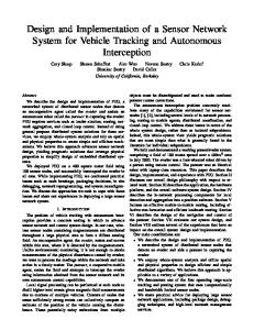
Fig. 1. Overview of ROV (a) Front view (b) Side view (c) Top view (d) Back view.
Fig. 2.
Layout of underwater experimental devices.
A. 3D Model-based Recognition using 1-step GA As the main sensor for this robot is visual sensor, the two fixed forward cameras are used for three-dimensional object recognition in visual servo. In the thruster system of ROV, 2 horizontal thrusters with maximum thrust of 9.8 [N], 1 vertical thruster with maximum thrust of 4.9 [N] and 1 lateral thruster with 4.9 [N] are installed. The specifications of main hardware components are summarized in Table.II. 2) Underwater Experimental System: A simple pool (length 2 [m] × width 3 [m] × height 0.75 [m]) filled with tap water is used as an experimental tank for underwater vehicle experiments. ROV receives image information and control signals through the tether cable (200m) connected to PC as shown in Fig.2. In order to perform docking experiments underwater automatic charging, a rod on the right side of the underwater robot and cylinder hole on the left side of the target were designed. When the robot is in the right relative pose to the object, then it has to move ahead to insert the rod into the cylinder hole. The block diagram of the proposed control system is shown in Fig.3.
Knowing the information (size, shape, color) of the target and desired relative pose to the AUV, the solid model of the target is predefined and projected to 2D images. Comparing the projected solid model image with the captured 2D images by dual cameras, the relative pose is estimated. Fitness value which is correlation function of projected model against the real target in the image is used as the evaluation parameter of recognition process. Even through there are classical computer vision algorithms to obtain the relative pose estimation, GA provides recognition performance in terms of effectiveness, simplicity and repeatable evaluation for real-time performance. Therefore, GA named as 1-step GA (Detail explanation can be seen in [1][2][4]) in this experimental system is capable of real-time recognition of the moving image effectively and confirmed in our previous works [3][5]. In this method, the genes which represent the different relative poses of 3D model to the ROV are initiated randomly. According to defined fitness function, the gene with the highest fitness function value represents the pose of the real target. Therefore, the searching problem of real target pose addresses the optimization problem. Through the steps of GA (Selection, Cross over and Mutation), a number of genes that represent different poses are evaluated by the defined fitness function to get the best gene with the most truthful estimated pose. This 3D model-based matching process is executed within 33 [ms] synchronizing with the video rate of dual-eyes camera. Table I shows the conditions of GA.
C. Underwater Experimental Conditions 1) 3D object recognition accuracy using GA: To describe the accuracy of the recognition by GA using dual-eyes camera, target object consisting of three spheres (40[mm] in diameter) whose colors are red, green and blue, and fixed to the main body box (100mm × 100mm × 100mm) as shown in Fig.4 was placed any place in the water during the experiment. The recognition of the pose of the object using 3D model-based matching and GA is assumed to be executed in GA search area set between the underwater robot and the object shown in Fig.4(b).
B. Underwater Experiment Environment 1) Underwater robot system: Remotely controlled underwater robot used in this experiment (manufactured by KOWA) is shown in Fig.1.
TABLE II S PECIFICATION OF ROV
TABLE I
Max: operating depth [m] Dimension [mm] Dry weight [kg] Number of Thrusters Number of Cameras
PARAMETERS FOR GA Number of genes Target variables Search area [mm] Control period [ms] Number of GA evolution
60 Positions (x[mm], y[mm], z[mm]), Posture (ε2 [deg]) {x,y,z}={±400, ±200, ±400} 33 9
Tether cable [m] Maximum thrust force [N]
990
50 280 (W) × 380 (L) × 310 (H) 15 2 (Horizontal), 1 (Vertical), 1 (Traverse) 2 (Front, fixed), 2 (Downward, fixed), 1 (Tilting and zooming) 200 9.8 (horizontal), 4.9 (vertical, Traverse)
Fig. 3.
Control logic for the proposed system.
respective thrusters are calculated from the P controller.
Fig. 4.
Horizontal direction : v1 = k p1 (zd − z) + 2.5 (1) (v1 = 0[V] for thrust 9.8[N] in zH of ΣH , v1 = 5[V] for −9.8[N]) Rotation (y-axis) : v2 = k p2 (ε2d − ε2 ) + 2.5 (2) (v2 = 0[V] for 0.882[N] in yH of ΣH , v2 = 5[V] for −0.882[N]) Vertical direction : v3 = k p3 (yd − y) + 2.5 (3) (v3 = 0[V] for −4.9[N] in yH of ΣH , v3 = 5[V] for 4.9[N]) 5[V ] (xd − x < −5[mm] for thrust in xH of ΣH is −4.9[N]) Traverse direction : v4 = 0[V ] (xd − x > 5[mm] for thrust in xH of ΣH is 4.9[N])
(a) 3D marker and (b) Underwater target and GA search space.
2) Conditions of Control: After recognizing the target object, the following relative pose between underwater robot and the target object (xd [mm], yd [mm], zd [mm], ε2d [deg]) is controlled so as to maintain, and was confirmed in the regulation performance. Furthermore, in order to verify the stability against disturbance, the disturbance from the experimental pool outside by physical force against underwater robots in regulation was added and confirmed that the vehicle can be restored to its original pose. It should be noted that numbers in blacked () is defined target value in [mm] at the time of fitting completion in docking experiment. ε1 , ε2 , ε3 in this experimental system represent the angle of x-axis (the pitch axis ), the angle of the y-axis of ΣH and the angle of z-axis (roll axis) as shown in Fig.5 respectively.
III. RESULTS AND DISCUSSIONS
A. The GA Recognition Accuracy in Water Fig. 6 (a) shows the time variation of the fitness value at the time of GA recognition of underwater robot that was regulated in xd = 0, yd = −67, zd = 600, ε2d = 0. It can be seen that the fitness value is maintained above 0.8 within a few seconds from the recognition start. According to the previous experiments, GA recognition accuracy is necessary to have the fitness value of 0.5 or more for good regulator performance [1]-[3]. The recognition accuracy was also evaluated in air using the same target that was used in this experiment. It was confirmed that the object recognition accuracy in water using GA was almost the same degree of fitness in comparison with the case in the air. This result addresses huge benefit of reducing frequency of doing experiments in water for testing every advanced step in recognition process.
xd = H xM = 0 (0), yd = H yM = −67 (−67), zd = H zM = 600 (350), ε2d = 0 (0) In addition, x[mm], y[mm], z[mm], ε2 [deg] represent the pose of the target object recognized by GA. In order to regulate the underwater robot with relative pose to the target, the following command voltage value v1 ∼ v4 fed to
B. Regulated Performance
Fig. 5.
The regulation performance without physical disturbances from outside the experimental pool is shown in Fig.6, where the coordinate system of the underwater robot is as shown in Fig.5 (left) with the longitudinal direction of the respective x-axis, y-axis, and z-axis. Fig.6 (a) is about the fitness
Coordinate system provided in underwater experiment.
991
value recognized by 1-step GA, (b) shows the position of underwater robots in the regulation as measured in 1-Step GA and (c)∼(f) represents the error between the relative pose of the target and the underwater robot respectively. Although error from the relative target pose appears constantly and the four thrusters operate simultaneously, there are some recognition errors of GA according to the cable tension during robot movement and reflected waves from the pool sides that occur due to water pressure changes with robot movement. However, the proposed system is able to regulate the relative pose by canceling these disturbance elements. C. Stability Against Disturbance
Fig. 7. Regulator performance with disturbance in z-axis direction: (a) fitness value, (b) error in z-axis direction, (c) error in z-axis direction(enlarged view from 105[s] to 110[s]) and (d) thrust in z-axis direction.
In order to verify the stability of the proposed system against disturbance such as collision or ocean currents, etc, the regulated performance was confirmed whether the proposed system can restore the relative pose to the object when applying external forces in the direction directions manually using the rod (Wood full length 2 [m]) from the outside of the experimental pool. It should be noted that the disturbance is done by pushing the robot to move 150 ∼ 200 [mm] between 1.5 ∼ 2.0 [s] in the transverse direction, upward direction and backward directions and to rotate degree 15 [deg] per 1 [s] for around a vertical axis. Regulator performance with disturbance in z-direction direction is shown in Fig.7. The stability in this paper means the property in which the underwater robot can be restored to the relative target pose of the object even a disturbance is given to the underwater robot. Fig. 7 shows (a) the fitness of GA recognition, (b) the error between the relative pose of the object target and underwater robots recognized for each variable and , (c) the same results of (b) enlarged view from 105[s] to 110[s]. The disturbance
has been added in each of the figures after 20 [s] and 60 [s] from the beginning of the experiment. In the period shown with (A) and (B) in Fig. 7(a), (b), (c), it is found that varying the thrust (torque) is applied to the thrusters in response to an error from the relative target pose while maintaining the visual servo although fitness is temporarily lowered when a disturbance is applied. In other words, it is possible to confirm that an operation for correcting the error has occurred and consequently will change the pose of the underwater robot to restore the relative target pose. From the above results, the proposed system can be restored to its desired pose within a few seconds for all of these disturbances. Therefore, it was confirmed to have the stability against external disturbance. D. Underwater Docking Experiments Using the Relative Pose Regulator Experiments were carried out with different start positions (a) front of 3D marker, (b) left side of pool against 3D marker, (c) right side of pool against 3D marker as shown in Fig.8. Fig. 9 shows the docking experiment carried out when the start position of underwater vehicle is in front of 3D marker following the four states (A) approaching to the object (Approach) (B) Visual servoing to keep the relative pose to the object (Visual servoing), (C) Fitting to the fixed homing unit (Docking) and (D) Fully fitting into the homing unit (Completion of docking) as shown in Fig .9(a). Approaching step, in which the speed of robot is low, means the state until the underwater robot finds an object
Fig. 6. Regulator performance without additional disturbance: (a) fitness value, (b) 3D trajectory of underwater vehicle, (c) error in x-axis direction, (d) error in y-axis direction, (e) error in z-axis direction, (f) error around y-axis.
Fig. 8. Start position of underwater vehicle: (a) front of 3D marker, (b) left side of pool against 3D marker, (c) right side of pool against 3D marker.
992
Fig. 9. Docking experiment result (start position of underwater vehicle: front of 3D marker, position (a) in Fig.8): (a) snapshot of docking experiment, (b) fitness value, (c) position in x-axis direction, (d) thrust in x-axis direction, (e) position in y-axis direction, (f) thrust in y-axis direction, (g) position in z-axis direction, (h) thrust in z-axis direction, (i) angle around y-axis and (j) torque around y-axis.
993
IV. C ONCLUSION In this study, we carried out underwater docking experiments, demonstrating the automatic charging in underwater, with regulating performance of the underwater robot using visual-servo by dual-eyes camera, to obtain the following conclusions: (1) Since it is possible to restore the relative target pose of the object with respect to physical disturbances in visual servo, the proposed system is stable against an external force disturbance. (2) From the results of the docking experiments, it was found to have a follow-up performance to varying target value in the z-axis direction. (3) By switching the Visual servoing and Docking based on the threshold of the error between the target position, it was found that it is possible to realize docking experiment. Aiming at the development of underwater automatic charging system in the future, we will complete the verification of the effectiveness of the proposed system in docking experiment at sea.
Fig. 10. Docking experiment result (start position of underwater vehicle: front of 3D marker, position (a) in Fig.8): (a) error in x-axis direction, (b) error in y-axis direction, (c) error in z-axis direction and (d) error around y-axis.
R EFERENCES [1] Song W., Minami M. and Aoyagi S., ”Feedforward On-line Pose Evolutionary Recognition Based on Quaternion”, Journal of the Robot Society of Japan, Vol.28, No.1, pp.55-64 (in Japanese), 2010. [2] Song W. and Minami M., ”3-D Visual Servoing Using Feedforward Evolutionary Recognition”, Journal of the Robot Society of Japan , Vol.28, No.5, pp.591-598 (in Japanese), 2010. [3] Yu F., Minami M., Song W., Zhu J. and Yanou A., ”On-line Head Pose Estimation with Binocular Hand-eye Robot based on Evolutionary Model-based Matching”, Journal of Computer and Information Technology, Vol.2, No.1, pp.43-54, 2012. [4] Wei. Song, M. Minami, Fujia Yu, Yanan Zhang and Akira Yanou, ”3-D Hand and Eye-Vergence Approaching Visual Servoing with Lyapunouv-Stable Pose Tracking”, IEEE Int. Conf. on Robotics and Automation (ICRA), pp. 5210-5217, 2011. [5] Suzuki H. and Minami M., ”Visual Servoing to catch fish Using Global/local GA Search”, IEEE/ASME Transactions on Mechatronics, V0l.10, Issue 3, pp.352-357, 2005. [6] Steve Cowen, Susan Briest and James Dombrowski, ”Underwater Docking of Autonomous Undersea Vehicle using Optical Terminal Guidance”, Proc. IEEE Oceans Engineering, Vol.2, pp.1143-1147, 1997. [7] Ken Teo , Benjamin Goh , and Oh Kwee Chai, ”Fuzzy Docking Guidance Using Augmented Navigation System on an AUV”, IEEE Journal of Oceans Engineering, Vol. 37, NO. 2, April 2015. [8] Michael D. Feezor, F. Yates Sorrell, Paul R. Blankinship, and James G. Bellingham, ”Autonomous Underwater Vehicle Homing/Docking via Electromagnetic Guidance”, IEEE Journal of Oceans Engineering, Vol. 26, NO. 4, pp.515-521, October 2001. [9] Robert S. McEwen, Brett W. Hobson, Lance McBride, and James G. Bellingham, ”Docking Control System for a 54-cm-Diameter (21-in) AUV”, IEEE Journal of Oceanic Engineering, Vol. 33, NO. 4,pp. 550562, October 2008 . [10] Ken Teo, E. An and P.-P. J. Beaujean , ”A robust fuzzy autonomous underwater vehicle (AUV) docking approach for unknown current disturbances”, IEEE Journal of Oceanic Engineering, Vol. 37, No. 2, pp. 143-155, April 2012. [11] Jin-Yeong Park , Bong-Huan Jun , Pan-Mook Lee , Fill-Youb Lee and Jun-ho Oh , ”Experiment on Underwater Docking of an Autonomous Underwater Vehicle ISimI using Optical Terminal Guidance”, IEEE Oceanic Engineering, Europe, pp 1-6, 2007. [12] Amaury N‘ egre, C edric Pradalier and Matthew Dunbabin , ”Robust vision-based underwater homing using self similar landmarks”, Journal of Field Robotics, Wiley-Blackwell, Special Issue on Field and Service Robotics, 25 (6-7), pp.360-377, 2008. [13] Matthew Dunbabin,Brenton Lang and Brett Wood, ”Vision-based Docking Using an Autonomous Surface Vehicle”, IEEE International Conference on Robotics and Automation,Pasadena, CA, USA, 2008. [14] Pedro Batista, Carlos Silvestre, and Paulo Oliveira, ”A Two-step Control Strategy for Docking of Autonomous Underwater Vehicles”, American Control Conference, Montral, Canada, 2012.
(recognition) assuming that the object is presented in front of underwater robot. In other words, underwater robot does not know the relative pose to the object in the initial condition, and then go forward and transits to a state of Visual servoing after discovered the object. Then, Visual servoing means a state in which the underwater robot keeps the relative pose to the object. After the transition to this state, the underwater robot moves forward (the relative target position zd decreases by 30 [mm / s] to zH -axis direction when the error of the relative position of the robot (xd and yd ) to the object is stable with ± 20 [mm] tolerance in image plane for minimum period of 165[ms] (5 times of the control loop). That goes to the state (Docking) to perform the fitting to the homing unit. However, when the range of the above-mentioned errors exceeds defined value in docking process, the underwater robot keeps visual servoing process for executing the docking process again. In the state of Visual servoing, when the error from the relative target pose between the object and the underwater robot reaches below the above-mentioned threshold, the process transits to docking in which the robot is intended to fitting into the homing unit while recognizing the target object. Docking process is done by performing visual servo until the robot moves to reach (xd = 0, yd = −67, zd = 350, ε2d = 0). In Completion of docking state, the underwater robot is intended to keep the relative target pose of the object in the connected state by mean of visual servoing. Fig. 9 (b)∼(j) shows the result of docking experiments with start position of robot in front of 3D marker. (b) is fitness, (c) (e) (g) (i) shows the pose of underwater robot, and the thrust and torque in each axis are shown in (d) (f) (h) (j) respectively. Fig. 10 represents the error from the relative target pose with respect to Fig.9. From each of the figures, the transition of the states; (A) Approach, (B) Visual servoing, (C) Docking and (D) Completion of docking can be seen. In other words, it can be confirmed that the underwater robot can achieve docking experiment using the proposed system. 994