Mine Water and the Environment | © International Mine Water Association 2006 | www.IMWA.info
71
Mine Water and The Environment, Vol12,Annual Issue, 1993, pp 71- 94
RECENT DEVELOPMENTS IN PUMPING SYSTEMS IN UNDERGROUND METALLIFEROUS MINING by V.S. Vutukuri Department of Mining Engineering University of New South Wales Kensington, Sydney, NSW 2000, Australia and R.N. Singh Head, Department of Civil and Mining Engineering, University of Wollongong NSW 2500, Ausaalia
INTRODUCTION Mine water is characterised by the presence of impurities including mineral salts in subsaturated or supersaturated conditions, suspended solids, dissolved carbon dioxide, oxygen, hydrogen-sulphideand other gases, and acid or alkaline mine water. Thus, the quality of mine water may cause pumping difficulties, corrosion to mine machinery and equipment within the mines and ecological problems when discharged on to the land or into streams or lakes. The materials in suspension can, in general, be separated out in "settling" sumps and acidity or alkalinity can be neutralised. The materials in solution create greater difficulties in pumping as it increases the viscosity of the fluid and consequently, increases the power cost of pumping. The materials in suspension are often deposited on the inner periphery of the pipes, forming encrustations which vary from a thin glaze to a rough laminated crust which is difficult to remove. The degree of deposition depends on the nature of the mineral content of the water, the conditions under which the pumps operate and the type of pumping equipment. Scaling of the delivery range not only increases the friction losses in pipes but also reduces the effective diameter of the delivery range. Acidic mine water, if not neutralised, will seriously shorten the life of pumps and pipe services, unless they are made of special materials or are specially protected. This papa briefly describes the modem trends in pumping in the metalliferous mining operations.
Reproduced from best available copy
Mine Water and the Environment | © International Mine Water Association 2006 | www.IMWA.info
DISPOSAL OF MINE WATER The main methods of disposal of mine water above the self-draining level is through drainage adits and tunnels and below the self-draining level is by pumping. It is essential, for efficient and economical pumping of mine water, that deleterious matter, such as grit must first be removed or acidity or alkalinity neutralised
Drainage tunnels
When the topography is suitabIe, adits may be driven as a self-draininglevel to dewater a mine or a group of mines. The advisability of such drainage tunnels is a matter of economics ie the cost of the adit, together with the capital cost and interest charges should be lower than the perpetual cost of pumping.
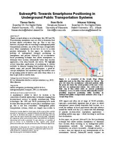
Figure 1. The Graton tunnel project for mine dewatering at Casapalca Mine in Peru (after Kincaid, 1970) Many drainage tunnels have been made in mining fields all over the world. A typical example of the drainage tunnel may be cited as Casapalca copper-lead-zinc-silver mine in Peru. The project was known as Graton tunnel project (Figure 1)which comprised driving two parallel tunnels one for haulage and one for drainage, totalling over 22.4 km in length. The project took some 10 years to complete at a cost of US$ 14 millions which included cost over-run by US$ 5.5 millions. The highest inflow rate during construction in period in 1970 was 11217 Vs.
Mine Drainage by pumping A traditional method of dealing with mine water is by pumping the untreated mine water. However, the mine water in metalliferous mining operations contains a range of impurities and suspended sediments or solids which may reduce the life of the pumping equipment or may cause in-repairable damage to the plant. This problem is further accentuated with the service water being introduced to the mine for dust suppression or/ and with hydraulic fill. As a consequence it is necessary to separate sediments from mine water before pumping. Figure 2 indicates a method of organising sediment separation and disposal in a rnetalliferous mining operations.
Reproduced from best available copy
Mine Water and the Environment | © International Mine Water Association 2006 | www.IMWA.info
Pumping dirty water (slurry pump)
Sidement Settlers
Repair or changing pumping plant and pipes i
Filterpress
I
I
Clear water
1
I
Slime mixed with solid ore or rock
I
Mud pumping
+
Solid cakes
Figure 2 Methods of dealing with sediments in mine water Basically two types of pumping systems are available: Direct pumping of run of mine water using slurry pump. Settling of run of mine water to produce clear water and thickened mud, with separate pumping facilities for each of these two products. The first system is usually preferred by most underground mines, essentially for reasons of simplicity. For high head and/or volume flow rate however, the system becomes prohibitive in terns of scale, capital cost and operating cost. Available slurry pumps fall into two categories: low head-high volume flow rate cenmfugal, and low volume flow rate-high head plunger pumps. Maintenance costs for slurry pumps are considerably higher than for clear water pumps on a per litre basis. Capital costs on a litre per second basis are orders of magnitude higher.
TREATMENT OF MINE WATER FOR PREVENTION OF CORROSION, EROSION AND ENCRUSTATION The treatment of mine water may be considered under two main headings; preventing corrosion, erosion and encrustation, and clarification of mine water before pumping. The corrosion and erosion in pumps can be chiefly attributed to the following factors: Acid water. Aerated water. Muddy water, pumping grit at high water velocity . Acid water Water emanating from the rock comes in contact with sulphide minerals and bacteria forming acidic mine water. The remedial measures to mitigate the effects of acidic mine water on ~ l a nand t equipment are as follows:
Reproduced from best available copy
Mine Water and the Environment | © International Mine Water Association 2006 | www.IMWA.info
Use of corrosion-resistantmaterials in the construction of pumps, mine plant and equipment. Neutralisation with lime or other chemical reagents but it leads to the precipitation of insoluble CaS04 which combines with other chemical compounds to form heavy and hard crystallineencrustations. In the past, the following three alternative techniques have been used to neutralise acidic mine water: (i)
(ii) (iii)
washing soda which eliminates encrustation,but is much more expensive particularly when dealing with large make of water. mixture of 75% lime and 25% soda. use of special chemicals - Aquoil, ferrous sulphate, etc. prevents CaS04 crust formation.
Aerated water
Water containing dissolved gases like C02,0 2 , nitrous or nitric gases, hydrogen sulphide and other gases can be released in the form of bubbles. A common cause of aeration is an inadequate suction pipe or suction pressure. By placing pumps below the clean water sump the danger of erosion in the pumps by aerated water should be eliminated. Provision of adequate ventilation of the sediment settler and pump house is therefore, necessary to remove noxious gases. Muddy water Mud consisting small particles of clayey materials is not harmful at normal velocities to the pumping plant. However, grit at a high velocity may cause strong erosive action to the pumping plant and pipes resulting in frequent and unpredictable breakdowns. Grit and mud is collected in the cleaning up of the drain systems that extend throughout a mine. It is also a common practice to clarify mine water before pumping in order to increase the pumping efficiency and reliability of the plant. The treatment of water prior to pumping is one of the most important factors in designing mine pumping layout. Pumps can be changed or additional pipe columns can be installed, but the layout of settling and clear water sumps with their associated pump chambers is permanent, and requires the closest consideration.
DESIGN OF SETTLING SUMPS Two methods of settling mud from run of mine water are available: Horizontal flow settler. Vertical flow settler.
Horizontal flow settlers (Long shallow sumps) In horizontal flow settlers, the incoming water enters at one end of a long sump and discharges at the other end over a battery of overflow lip launders (Figure 3). The overflow is then channelled along a collecting launder into the clear water sump ahead of the pumps. The pattern of sludge deposition in the horizontal flow settler is such that the coarse particles come out of suspension in the first few metres, rapidly building up sludge at the inflowing end. Since the flow is local through the body of the settler, little further settling occurs until the water reaches the collecting end. A secondary build-up of sludge of finer particles occurs under the ovefflow launders, ie. in the region of almost wholly vertical flow. As the sludge build-up grows and extends into the settler from the end walls, the efficiency of the settler decreases. As a result, progressively
Reproduced from best available copy
Mine Water and the Environment | © International Mine Water Association 2006 | www.IMWA.info
larger particles arc carried over into the clear water sump. When the size and quantity of solid material entering the clear water sump becomes excessive, the settler requirts cleaning. If the settler is not cleaned in time, the clear water sump becomes partially fded with sludge which can reach the pumps, causing accelerated wear and damage.
- ,,
I .
sludge build-up
Figure 3. Section through a horizontal flowing actual flow pattern and typical sludge pile growth (after Goninan, Gmdzinskas and Fleming, 1968)
When cleaning the settier, the inflowing water is by-passed to feed ditectly into the back of the clear water sump. The water above the sludge in the settler is then decanted into the clear water sump after the level in the clear water sump has been pumped down as low as possible. The mud near the outer settler wall is then agitated into a slurry with high-pressure air and water jets. It is then either gravitated to a stope on a lower level or fed to a plunger pump which l i i it to a higher level. To clean the clear water sump, the water levels in both the settler and clear water sump are lowered as far as possible. Mine water is then run into the settler while the clear water sump is being cleaned. Vertical flow settlers (Short deep sumps)
Discharge Feed
d
Figure 4. Two types of vertical flow settlers (after de Villiers, 1961). (a) with one wall, (b) with two walls.
Reproduced from best available copy
Mine Water and the Environment | © International Mine Water Association 2006 | www.IMWA.info
The water is led into the bottom of a deep sump at such a rate that the velocity of the rising water is less than that of the descending particles. These solid particles will settle out in accordance with their relative specific gravities, the largest particles going to the bottom and the finest particles to the top, of course, they are the most easily disturbed by any current in the water. Two types of vertical settlers are shown in Figure 4 (de Villiers, 1961). In design (a) the inflow water is taken to below the bed of settling particles behind a wall. The excavation width governs the length of the horizontal flow. A more stable condition can be obtained with design (b). In this case, the length of the horizontal flow is reduced to only half the width of the excavation at the bottom of the divergent upward flow portion. This opening must not be made too narrow as this would trap the settling particles in the upward flow portion and create unstable conditions. In both cases, the settled sludge must not be allowed to accumulate to such an extent that the openings at the bottom of the walls become resmcted, as this would result in settled particles becoming reentrained. The double baffle settler ie. type (b) is best but may be uneconomical to build, so a compromise may be made with the single baMe ie. type (a). The double baffles slope at 16.5'. The upward velocity of the water steadily decreases due to the divergence of the baffles. Fine particles are carried up until they reach a level at which the velocity of the water is equal to their settling velocity. For constant flow the particles remain at their respective teeter levels and form a flocc blanket across the settler. As the density of the flocc builds up it acts as a filter to smaller particles. Coagulation and settlement of the large lumps keeps the blanket in equilibrium. Modifications to the conventional Flocculation
vertical
flow settler concept
The free settling velocity of particles of the size of about 5 pm is about 3 mm/minute. The use of flocculating agents avoids large settling areas underground. In the case of Mount Lyell mine, 1 kg of anionic flocculant (cost - $A4) per megalitre of run of mine water increases minimum free settling velocity dramatically to 300 mrnlminute (Atkinson, 1982). Flocculants are long chain polymers which bridge between solids in suspension, resulting in agglomerates of entangled particles. These agglomerates, or "floccs" are typically 1.5 mrn in diameter with a free settling velocity up to 500 mdminute. These large floccs will continue to form provided the influent contains solid particles. The flocc forms rapidly and decreases the concentration of flocculant in the suspension fluid rapidly. Consequently a fair proportion of rogue particles remain in suspension. It is possible to capture these particles by passing the fluid upward through a "filter bed" of previously flocculated particles. Flocc bed settler
Flocc bed settlers have been originally developed in South Africa (Soutar, 1977). In general a flocc bed settler can be either single compartment type or a double-V compartment vertical flow type settler. A double-V compartment vertical flow (flocc bed) settler as installed in Mount Lyell mine is shown in Figure 5 (Atkinson, 1982). Run of mine water is introduced along the feed launder (1) and fed vertically to the bottom of the flocc bed (2) at a controlled rate via control valves (3) and feed pipes (4). To maintain steady flow rates within the flocc bed, the 38 mm diameter pipes are closely spaced (300 mm centres) along the length of the settler. The influent rises vertically through the flocc bed at a decreasing velocity due to the divergent walls of the settler. As the flocc bed has a higher specific gravity than that of the influent it is inherently unstable. If the influent velocity (Vi) is equal to the free settling velocity (Vf) of the
Reproduced from best available copy
Mine Water and the Environment | © International Mine Water Association 2006 | www.IMWA.info
flocculated particles the system is kinetically stable. As the filtering action of the flwc bed entraps more solids the specific gravity increases, but at the same time the upward velocity of the influent increases, due to the growth of the flocc particles and the reduction in the interstitid spaces between them. The flwc bed exhibits a net increase in size and overflows from the top of the brattice wall (5), thereby maintaining a constant slurry density within the flocc bed of about 7% solids by weight.
(1) Feed launder (2) Hocc bed (3) Conml valves (4) Feed pipes - 38 mm diameter (5) Brattice wall (6) Quiescentportion of the settler 0)Mud bung (8) Mud drain column (9) Bung valve (10) Clear water overf3ow launder Vi Influent velocity VfFIIXsettling velocity of the flocculated pamc
Figure 5. Flocc bed sealer for Mount Lyell Mine (after Atkinson, 1982).
Reproduced from best available copy
Mine Water and the Environment | © International Mine Water Association 2006 | www.IMWA.info
The flocc bed overflow passes into a quiescent portion of the settler (6) where further thickening occurs. The thickened mud is drawn off via a mud bung (7) and mud drain column (8). Provision is made for bleeding of the flocc bed via a bung valve (9). The clear water elutriates from the surface of the flocc bed and rises to the clear water overflow launder (10). In practice the settler is partitioned longitudinally into cells 5 m long. Each cell has a design capacity of 60 Us. The flocc bed cells are intended for removal of particles smaller than about 100 pm, and in fact tend to become choked by coarser material. The run of mine water at Mount Lye11 carries a significant proportion of such particles, and for this reason two rougher cells have been included upstream of the brattice cells for removal of sand and grit. These cells are equipped with a central feed well but with no brattice walls. Water with finer panicles in suspension will overflow into the launders feeding the bratticed flocc bed cells. Ten such cells are arranged along the sealer drive giving a total installed settling capacity of 600 Vs. The settler system produces thickened mud with a solids content up to 15% by weight. The mud generation rate is up to 10% of the run of mine inflow rate. This mud is stored in an air agitated mud dam of 400 kilolitres capacity (10%of 4 mega-limes).
CLEAR WATER PUMPING There are three different configurations which are principally used for a mine's main pump stations. These are: (i) Horizontally mounted multi-stage, centrifugal clean-water pump, driven by a non-submersible electric motor. (ii) Horizontally-mounted non-submersibleelectrically-drivencenmfugal pump of heavy duty design. (iii) Fully submersible electric pumping unit. Multi-stage clean-water pump arrangements suffer from a number of disadvantages. Inability to pump water contaminated with abrasive particles. The motor is not water-proof and hence there is a risk of complete breakdown if flooding occurs. Servicing difficulties. Limitationsof mobility. A drainage system is required in order to drain water downwards before pumplng it up again. These difficulties can be overcome by the use of large heavy-duty head submersible main pumps in combination with submersible feeder pumps (Figure 6) (Anderson, 1990). These pumps are not only impervious to damp and water, but are also able to handle contaminated water including abrasive particles. Maintenance is facilitated by the relative ease of transport of such pumps and excavation costs for the pump station are likely to be lower. Submersible pumps are now available in sizes from the smallest of 1 kW up to the largest typical main pump of 90 kW with a maximum output of about 150 Us. A more powerful 200 kW pump is also now available. Figure 7 shows cross-section of the BS2540 submersible dewatering pump manufactured by FLYGT. The optimum operating point for this pump is 36 I/s at a head of 285 m.
Reproduced from best available copy
Mine Water and the Environment | © International Mine Water Association 2006 | www.IMWA.info
Figure 6. Use of submersible pumps in an underground mining operation (Anderson, 1990) A cost study for a hypothetical pumping system was canied out for a feeder pump station at 380 m and a main pump station at 360 m below surface (Anon 1987) The feeder pump transfers raw water to the main station at a rate of 60 m3/hour (167 Us). The mine water contains suspended solids of medium abrasiveness at a concentration of 1.5 g/l. Taking account of alI capital and operating costs, the comparison showed a 30% differential in favour of unsettled submersible pumping (Stock and Hodinott, 1987).
The overall conclusion of the study is that clean water systems are still likely to be used in the very deep mines and in mines where the water is very clean, but that in other applications, submersiblesarc increasingly showing advantages.
Reproduced from best available copy
Mine Water and the Environment | © International Mine Water Association 2006 | www.IMWA.info
ra
Figure 7. The BS 2540 submersible dewatering pump (Anderson, 1990).
MUD PUMPING Over the past thirty years there has been a rapid revolution of mud pump design; from conventional plunger pumps, to oil interface plunger pumps, to culmination in hydraulic mud displacement. The mud displacement system has been developed and refined in South Africa to the point where it is extremely cheap to operate, relatively cheap and simple to install, and reliable.
Mars pump
The Mars pump is a twin-cylinder, double-acting type and has a cylinder bore of 225 mm and a stroke of 450 mm. The maximum pressure specified by the makers is 7850 kPa, and the displacement is 136.3 m3/hour at a specific gravity of 1.28. In principle, this pump differs from conventional reciprocating pumps in that it isolates the abrasive slurry from the cylinders by interposing a mass of oil between them as indicated in Figure 8.
Reproduced from best available copy
Mine Water and the Environment | © International Mine Water Association 2006 | www.IMWA.info
Reproduced from best available copy
Mine Water and the Environment | © International Mine Water Association 2006 | www.IMWA.info
(1) Displacement chamber (2), (3) Gate vaives
17 L M L
AL-220
(4) Mud charge pump (5) Mud dam (6) Qear water dams (7)IIeader &m (8) Mud rising main (9), (10) Non- turn valves (11) Small stage pump (12) Clear water rising main (13) Clear water pumps
Figure 9. Diagrammatic layout of mud displacement scheme (after Atkinson, 1982) Mud displacement system
The system designed for Mount Lyell mine is essentially utilises the potential energy of water stored at a suitable elevation above the mud discharge point. The water also serves to act as a mechanical piston. An ideal arrangement is shown in Figure 9. The Displacement Chamber (1) consists of a vertical steel cylinder, 1.5 m diameter, 20 m
Reproduced from best available copy
Mine Water and the Environment | © International Mine Water Association 2006 | www.IMWA.info
Figure 10.Schematic -drainage and pumping T-1area (after Devlin and Goddart, 1977)
Reproduced from best available copy
Figure 11. Slimes pumping arrangement 4080-ft (1244-m) level (after Devlin and Goddard, 1977).
Mine Water and the Environment | © International Mine Water Association 2006 | www.IMWA.info
Reproduced from best available copy
Mine Water and the Environment | © International Mine Water Association 2006 | www.IMWA.info
high,concreted into a winze. At the start of the operating cycle the chamber is full of clear water (from the previous cycle). With gate valve (2) open, and gate valve (3) closed, the mud charge pump (4) starts. Mud is drawn from the mud dam (5), and is pumped into the bottom of the chamber, displacing water back to the clear water dams (6). The mud charge pump is a conventional 150mm by l00mm centrifugal pump with a design point of 40 Vs, 15 m total lift, and a maximum NPSH (net positive suction head) of about 10 m. Due to the large diameter of the chamber and the difference in specific gravity of the mud and the water, very little mixing occurs across the mud-water interface. When the chamber is filled with mud to about 90%of total capacity, the mud charge pump stops (this ensures gate valves (2) and (3) never encounter mud). Valve (2) then closes, and (3) opens, introducing high pressure clear water from a header dam (7) located on surface at RL 340. As the pressure of the column of clear water exceeds the pressure of the column of mud in the mud rising main (8) by some 1500 kPa (assuming a mud specific gravity of 1.2). the mud rises to discharge at RL 195. The clear water is injected into the chamber until the non-return valve (9) and mud rising main (8) are flushed. This involves injection of more water than the volume of mud actually displaced. It should be noted, however, that the volume of water which is returned to the clear water dam for repumping is exactly equal to the volume of mud displaced. The planned cycle time is about 30 minutes; with a chamber volume of 35000 1, a maximum net mud pumping rate of 20 Vs is possible. One of the features of the system is the small number of mechanical parts exposed to high pressure mud. In fact non-return valve (9) is the only valve which is required to close against mud. All items operate only once every 30 minutes. This compares favourably to a plunger pump which may have up to 12 non-return valves opening and closing in mud at up to 10 times per second.
Mud dis~lacemenywater suDDlv: A small stage pump (1 1) draws water from the clear
water rising mains (12) whenever any of the main 18 Level clear water pumps (13) are operating, and the header dam water level demands topping up. The capacity is some 90% of each of the pumps in the 18 Level pump station, ensuring flooded pump suction without the need for an intermediate dam on 11 Level. The header dam capacity is sufficient for up to 10 chamber cycles.
CASE HISTORIES Pumping practice in a mine using hydraulic fill in Thompson mine
The mine comprises 630 t per day Nickel-Copper operation some 640 km due north of Winnipeg (Manitoba where ore is produced by 1350m deep T-1 main production shaft. Sandfill is poured at an average of 60% solids by weight (35% solids, 65% water by volume), and the flow rates average 63 Vs. The water discharge from the fill being placed averages 50.5 Vs, including flush water. Most of the drainage water is from the sandfill operations 12.52 Vs with a slimes content of 0.25% by weight i.e. 30 tonnes of slimesjweek. The haulage and extraction drifts are driven at a + 0.3% grade. Level drainage flows to three main drain hole systems. The sumps are below base of rail and each sump is equipped with two 150 x 150 mm rubber lined vertical slurry pumps. One pump in each sump unit operates as required, while the other pump is a standby unit. This drainage water is pumped through an 200 mm pipeline on the 732-m level to the T-1 drain hole system (Devlin and Goddard, 1977). All drainage water discharges from the 1219-mlevel into the main sumps on the 1244-m level. The slimes from these sumps are drained into the Mars pump system, while the clear water is pumped to the 500-m level by three 50.5 Us 14-stage pumps (Figures 11) and then pumped to surface by three 50.5 Us 10-stage pumps.
Reproduced from best available copy
Mine Water and the Environment | © International Mine Water Association 2006 | www.IMWA.info
Figure 12. Mine drainage at Coleman mine (after Callahan, 19791.
Reproduced from best available copy
Mine Water and the Environment | © International Mine Water Association 2006 | www.IMWA.info
The two sumps on the 1244-m level are located 5.5 m above base of rail in order to facilitate feeding the slimes to the Mars pump system and to provide a positive suction head for the clean water sumps. Design of the sump was based on scale model testing in 1969. The sumps were designed with a large area 6 m wide in the slimes settling end, with baffles and dams to reduce the drain water velocity to less than 0.5 c d s . The drainage water is fed to both sumps simultaneously, so that each sump receives one-half of the drainage water. Approximately 90% of the slimes settle out in the V-shaped collection area in the bottom of the sumps, and each sump supplies 50% of the feed to the Mars pump system. Water is used to dilute the slimes in the Mars pump mixing tank to the required pulp density. Twin agitators maintain a uniform feed mix to the Mars pump. The slimes are pumped to the 610-m level Mars pump capacity 16.7 Vs, and then to the tailings sump in the mill for disposal in the tailings area.
Slime Disposal with ROM ore at Coleman mine Coleman mine is situated 56 km west of Sudbury, producing 3800 tonnes per day of Nickel-Copper ore from their underground mining operations. A slime removal system comsumes 466 Vs of water and is designed to be handled by a clarifier and resulting slime is removed by a piping system from the clarifier directly delivering it to the loading pocket. Slimes travel by gravity, and are automatically fed into each of two 9 tonne skips as part of the automated skip loading and hoisting cycle. The clarifier/sump is 32 m long, 4.9 m wide, 5.9 m high (Figure 12). Thickener- 4.9 m square cemented sump excavated 1.5 m deeper than the clarifier. A 4.3 m diameter rake moving at 0.5 rpm draws the slimes to the centre of the sump where a cone is located. The top of the cone is 0.66 m in diameter and the bottom is 0.15 m in diameter with a flanged pipe fitting. At this point the slimes consist of 10% ta 15% of solids by weight.
68 1 of slimes are injected into the loading hopper on top of the ore. Water from the slimes is absorbed into the ore and loading into the skip takes place without increased spillage in the shaft (Callaghan, 1979).
Clear water and Mud pumping systems at Mount Lyell Mine Mount Lyell Mine is situated near Queenstown, Tasmania. Annual rainfall in the mine area is 2500 rnrn. Run of mine water has a high solids content. The particles size distribution covers the spectrum from colloidal to 6 rnm diameter. Run of mine is treated in vertical flow settlers to produce clear water and thickened mud each of which is disposed of separately. The clear water is pumped by six 1000 kW conventional centrifugal pumps. The thickened mud is removed by a hydraulic displacement system. The rising mains for both the mud and the clear water are stainlesz steel cased boreholes (Atkinson, 1982). The cave material contains about 10% pyrite (FeS2) which combines with water and atmospheric oxygen to ultimately produce sulphuric acid and colloidal femc hydroxide slime.
Reproduced from best available copy
Mine Water and the Environment | © International Mine Water Association 2006 | www.IMWA.info
pH value - 3.0 to 2.3 Chemically inert materials - used in all pumping installations- plastics, timber, fibreglass, tar epoxy, grade 316 stainless steel. The Tariff is assessed from the Maximum Power Demand in any 15 minute period, and that tariff rate is then paid for the full three monthly quarter in which it occurred. Therefore minimise total pumping rate by having large dam capacity. Installed pumping capacity - 600 Vs
Dam capacity - 4 Ml
Figure 13 shows longitudinal schematic of mining areas. Figure 14 gives longitudinal section through clear water dams and Figure15 gives clear water suction details.
Figure 13.Longitudinal schematic of mining areas at Mount Lyell ( Atkinson, 1982).
Reproduced from best available copy
Mine Water and the Environment | © International Mine Water Association 2006 | www.IMWA.info
Figure 14. Longitudinal section through clean water sumps at Mount Lyell (after Atkinson, 1982).
Figure 15. Clean water suction details at Mount Lyell (after Atkinson, 1982). Use of diaphragm type slurry pump by Westmin Resources In August 1985,Wesunin Resources installed a Zimpro pump at its mine-mill complex at Myra Falls in British Columbia. The pump is designed to transport slurry at the rate of up to 4.5 l/s at pressures up to 14 MPa The system delivers a slurry of gravel and slimes through a vertical distance of 700 m followed by a further horizontal section of over 750 m. The slurry is collected underground in sumps and is then agitated before being fed at about 6 bar to the high pressure pump. The specific gravity of the slurry is about 1.3, while the pulp density is up to 45%.( Anon , 1987) The majority of sludge and slurry to be pumped from the underground workings is usually derived from the concentration of fine suspended solids in the mine water in especially excavated settling chambers. Zimpro pumps operate on the principle of isolating the hydraulic circuit and fluid from the slurry to be pumped by flexible diaphragms. The high pulp density slurry (up to 73% solids) fills one of two pressure vessels, collapsing a tubular diaphragm the inside of which is connected to the hydraulic circuit. The oil in the diaphragm is displaced to
Reproduced from best available copy
Mine Water and the Environment | © International Mine Water Association 2006 | www.IMWA.info
one of the two control cylinders where it pushes a free-floating piston from the top to the bottom of the cylinder, which ntums oil to the hydraulic package (Figure 16).
Figure 16. Flow diagram for Zimpro pump. Slurry enter at (1) and is pumped by pressun vessels (2), fitted with diaphragms and controlled by hydraulic cylinders (4) and (7), leaving at (11). In the filling process the opposite is taking place in the sister circuit with the hydraulic package delivering oil to the stroke control cylinder, which pushes up the free-floating piston, thereby filling the flexible diaphragm with high pressure oil which in cum displaces the slurry in the pressure vessel into the discharge line. The pump is essentially pulseless in its delivery and can operate at rates as low as 6 cylces/minute. Kidd Creek mines
The underground operations stage pump an average of 3 m3/minute (16.7 Vs) of water through 400 m. On arrival at the pumping station, the mine water contains approximately 5% solids by weight, which arc largely removed in settling cones. The resultant sludge contains 35% solids by weight, accumulates at a rate of 62 m3/day and is soupy and thixompic in nature. As a result, removal of sludge by LHDs mated mechanical problems, serious spillage occurred during transportation in mine cars and overall sludge handling was proving inordinately expensive. The mine management decided to thicken the sludge to a manageable density. Two principal techniques were identified: filter pressing and chemical flocculation, and since the latter did not require a significant capital outlay its implementation was attempted first (Walter, 1988).
Reproduced from best available copy
Mine Water and the Environment | © International Mine Water Association 2006 | www.IMWA.info
Figure 17 General arrangement of sumps and sediment settlers at Kidd Creek Mine (Walter, 1988) Following a sludge sampling and analysis program and testing with various reagents supplied by Drew Chemical Ltd it was found that "Amerfloc Plus" achieved immediate flocculation and a product of 60 - 70% solids by weight with no problems of toxicity or environmental impact. Following the laboratory program the technique was applied first to an underground settling cone and subsequently in the underground sumps. The results were encouraging, producing a non-thixotropic, viscous sludge with an angle of repose of 40 +I-.As a result the volume of sludge to be handled was reduced by approximately 50% and sumps can now be rapidly and effectively desludged by application of an 6.1 rn3 LHD with marked economies in handling costs. The thickened sludge is disposed of by mixing with rock in the rock-pass system or by despatching to bacHill sections. The general arrangement of settling cone and sumps layout is shown in plan in Figure 17 . Figure 18 shows the schematic view and the section through sumps and sediment settlers.
Reproduced from best available copy
S W
Reproduced from best available copy
5,000 US gallons
RETURN AIR DRIVE
12,000 US gottons
12,000 US oallons 13.000 US gallons
z a U
w
::
U
("
Q!
W
2!
lltOmGC L M T L O C t U M l ntl L M
w
-
-
,
TO 1-
-
,
ra&tslrtml toc
-
ICI-SOX
M J
L(LIQ~
w-'a
-
8 C)
P