SEL-321 Data Sheet Phase and Ground Distance Relay, Direction Overcurrent Relay, Fault Locator
Major Features and Benefits ➤
➤ ➤ ➤ ➤ ➤ ➤ ➤ ➤ ➤ ➤ ➤ ➤ ➤
Four Zones of Phase and Ground Distance Protection: ➢ Mho characteristic phase element ➢ Mho and quadrilateral characteristic ground elements Supports all standard tripping schemes Phase, negative-sequence, and residual overcurrent protection Two independent negative-sequence directional elements Apply to single- and three-pole trip installations Out-of-step tripping and blocking Unique load-encroachment logic Oscillography data and an 11-cycle event report Up to 16 contact outputs and 8 contact inputs in the One I/O Board version Up to 32 contact outputs and 16 contact inputs in the Two I/O Board version SELOGIC® control equations Three serial communications ports Front-panel setting and display Automatic self-testing; Fault locating; Metering
Schweitzer Engineering Laboratories, Inc.
SEL-321 Data Sheet
2
General Description The SEL-321 Relay protects, controls, and monitors EHV, HV, and subtransmission lines. The relay contains all protective elements and control logic to protect any overhead transmission line. The relay is a complete protective relay package for pilot and non-pilot schemes. The following list highlights a few of the protective features of the SEL-321 relay. ➤ Four zones of phase and ground distance protection ➤ Independent internal, user-settable timers delay Zone 2, 3, or 4 phase and ground elements for time-stepped coordination with downstream relays ➤ Any zone may be set forward or reversed ➤ Independently set phase and ground distance elements ➤ Ground distance can be selected for mho characteristic, quadrilateral characteristic, or both ➤ Quadrilateral characteristic on ground distance element adds sensitivity for high-resistance faults, compensates for load flow, and prevents over- and underreaching ➤ Positive-sequence memory polarization provides expanded resistive coverage for phase and ground faults ➤ Independent phase, negative-sequence, and residual time-overcurrent elements ➤ Four levels of instantaneous/definite time negativesequence and residual overcurrent elements ➤ Typical operating time of one cycle for three-phase faults
➤ Oscillography and event reporting data ➤ Front-panel setting and display
SEL-321 Relay Benefits The relay offers a large number of protective elements and features. You tailor the relay to your particular application using SELOGIC control equations to select specific functions. If your protection requirements change, the relay is readily adapted by entering new settings. The logic required for the new scheme is enabled, and those settings are entered. This allows change or expansion at no cost since additional protective relays or logic cards are not required. The relay has six independent setting groups. With this increased flexibility, the relay may be configured for virtually any operating condition: substitute line relay, line configuration changes, source changes, etc. Benefits gained using the SEL-321 relay include: ➤ Application flexibility ➤ Simplified settings: set only the elements you are using ➤ Relay is readily expanded to more complex schemes at no cost ➤ SELOGIC control equations allow you to program the relay to meet any application needs ➤ Fault locator reduces patrol and outage time ➤ Communications handle remote interrogation ➤ Self-testing increases relay availability
Applications Versatility The SEL-321 relay handles all overhead line protective relaying applications because it is both versatile and economical. The programming versatility of the relay allows use in pilot and non-pilot schemes. The relay fits a large number of applications. Basic schemes can be implemented by only selecting the elements used for that relay application. For more complex schemes, select more protective elements.
Communication Schemes The SEL-321 is the ideal relay for use in communications-based schemes. Dedicated SELOGIC control equations allow selection of relay elements to SEL-321 Data Sheet
perform specific functions when external conditions are met. In addition to the communications scheme logic, the SEL-321 provides time-stepped backup protection without the need for external wiring modifications or dedicated input contacts. The SEL-321 overcomes typical deficiencies associated with communications-based schemes. Most communications-based schemes are vulnerable to conditions that may result in an incorrect trip if logic is not provided to account for them. For example: ➤ Current reversals ➤ Weak-infeed conditions at one terminal ➤ Breaker open at one terminal ➤ Switch-onto-fault conditions
Schweitzer Engineering Laboratories, Inc.
3
While communications equipment circuitry can account for these shortcomings, it may not be available for applications where only the protective relaying is being upgraded, or when dependence on this external circuitry is neither economical nor desirable. The SEL-321 logic accounts for the deficiencies listed above. If the communication channel is lost or out of service, time-step backup protection is provided without special switching of detection detection schemes. The SEL-321 is capable of supporting permissive overreaching transfer trip scheme, direct and permissive underreaching transfer trip schemes, direct transfer trip schemes, and directional comparison blocking and unblocking schemes.
Obsolete Relay Replacement The SEL-321 is an ideal replacement for aging or obsolete elecromechanical relays. If protective relays are to be upgraded at one terminal only, it is important that relays have measuring principles compatible with surrounding terminals.
Compact size and simple field wiring make replacement of electromechanical relays with an SEL-321 especially convenient in crowded substations. Both horizontal and vertical mounting configurations are available. The required panel cutout dimensions are equivalent to that of a single electromechanical distance relay, which eliminates panel cutting where relays already exist. Event-reporting and fault-locating features economically provide valuable engineering and operating information, eliminating the need for event recorders and oscillographs in most applications. A negligible instrument transformer burden makes the SEL-321 an attractive alternative for overburdened current and potential transformers. Applications include: ➤ Single- or multiple-zone relaying schemes ➤ Time-stepped distance schemes ➤ Communications assisted schemes ➤ Single- and three-pole tripping ➤ Overcurrent protection with phase or ground distance supervision ➤ Replacement of electromechanical relays ➤ Substitute line relay
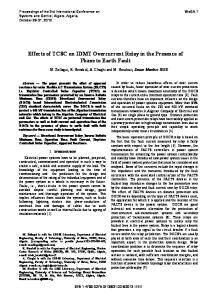
Operating Principles Mho Distance The SEL-321 uses mho characteristics for phase and ground distance protection. Figure 1 illustrates the impedance characteristics of the phase and ground distance elements. X Axis
Positive-Seq. Line Angle
Zone 4
All mho elements use positive-sequence polarization that expand in proportion to the source impedance, and provide positive, secure operation for close-in faults. Figure 2 shows the forward-reaching mho characteristic for a forward phase-to-phase fault. The mho circle expands to the source impedance ZS, but never more than the set relay reach, ZR. Positive-sequence memory polarization provides added security during the open-pole period when used in single-pole trip applications.
Zone 2 X Axis
Zone 1
ZR Memory No Memory R Axis Zone 3 (Shown Reversed) R Axis ZS 2 ZS
Figure 1 Phase and Ground Mho Distance Characteristics
Schweitzer Engineering Laboratories, Inc.
Negative-Seq. Directional Element
Figure 2 Phase-to-Phase Element Response for a Forward Phase-to-Phase Fault
SEL-321 Data Sheet
4
Quadrilateral Distance
Overcurrent Elements
The relay also provides ground quadrilateral characteristics. The top line of the quadrilateral characteristic compensates for load flow to avoid under- and overreaching. The ground mho and quadrilateral distance elements may be used individually or concurrently.
Phase, negative-sequence, and residual overcurrent elements provide primary or backup protection. Phase and ground distance elements can supervise the overcurrent elements for greater selectivity.
Negative-Sequence Directional Element
X-Axis
Zone 4
The relay uses a unique negative-sequence directional element, which calculates the negative-sequence impedance at the relaying point. Thresholds are set that declare the fault in the forward or reverse direction. Figure 4 illustrates the negative-sequence directional measurement technique.
Zone 2 Zone 1
R-Axis
Zone 3 (Reversed)
Figure 3
Negative-Sequence Directional Element
Quadrilateral Ground Distance Characteristics Source S Relay Source S
Source R ZS
ZR
ZL
RF
RF
Reverse Fault Z2 Measured
Forward Fault Z2 Measured
Z2 Impedance Plane
+X2 Z2R + Z2L
Non-Compensated Descision Line
Reverse
X2 = 0
Forward Z2S
Figure 4
Negative-Sequence Directional Element Measurement
SEL-321 Data Sheet
Schweitzer Engineering Laboratories, Inc.
5
Load Encroachment
Time-Overcurrent Elements
A load-encroachment feature prevents operation of the phase elements under high load conditions. This unique feature permits load to enter a predefined are of the phase distance characteristic without causing a tripout. Figure 5 shows the load-encroachment characteristic.
There are three independent time-overcurrent elements: phase for backup phase fault protection, negativesequence for sensitive phase-to-phase fault detection or ground fault detection, and residual for ground fault detection.
Torque Control M4P
Shaded Region Shows Area Where 3-Phase Mho Elements Are Blocked
M3P M2P
PLAR
M1P
PLAF
ZLR
NLAF ZLF
NLAR
Figure 5
The phase overcurrent element may be torque-controlled by the Zone 2 phase distance elements. The negativesequence and residual overcurrent elements may be torque-controlled by the Zone 2 ground distance or negative-sequence directional elements.
Load-Encroachment Characteristic
Scheme Selection With a simple setting, any of the four zones of phase and ground distance protection may be set in the forward or reverse direction. The number of phase or ground distance zones is selectable. Select mho and/or quadrilateral characteristic for ground distance. Mho elements give speed; quadrilateral elements give sensitivity. Each of the eight ground elements has its own reach setting.
Ground Distance Elements The ground distance elements include two zero-sequence compensation factors (k01, k0). This allows compensation for remote faults when there are intermediate sources of zero-sequence current; such as lines with tapped transformer banks with a grounded-wye configuration.
Negative-Sequence/Residual Overcurrent There are four levels of instantaneous/definite time negative-sequence and residual overcurrent protection. Each level provides backup protection. The instantaneous output of each level finds use in the communications scheme and control logic.
Communications-Based Schemes The relay supports the following communications-based protection schemes: ➤ Permissive Overreaching Transfer Trip (POTT) ➤ Permissive Underreaching Transfer Trip (PUTT) ➤ Directional Comparison Unblocking (DCUB) ➤ Directional Comparison Blocking (DCB) ➤ Direct Underreaching Transfer Trip (DUTT) ➤ Direct Transfer Trip (DTT) Current reversal logic provides for POTT, DCUM, and DCB scheme applications. To preserve the security of the parallel healthy line, the relay uses reverse Zone 3 elements, timers, and associated logic to block permissive tripping in POTT and DCUB schemes. In DCB schemes, the block trip signal transmission time is extended to allow time for the remote Zone 2 elements to drop out.
Additional Features Front-Panel Display The LCD display, Figure 6, gives detailed information pertaining to a fault detected by the relay, by displaying meter information, relay self-test status information, and settings parameters. Sixteen LEDs on the front panel give targeting information, fault type, and type of tripping.
Schweitzer Engineering Laboratories, Inc.
LCD Indicator LED Indicators
Control Pushbuttons
Figure 6
SEL-321 Front-Panel Layout
SEL-321 Data Sheet
6
Serial Communications Ports The relay has three serial communications ports for local or remote access to relay settings, meter, and fault data. Two serial ports are on the rear panel, and a local interface port is provided on the relay front panel. Remote communications allow operators to retrieve relay fault and meter information from a central control station. A multi-level password security scheme impedes unauthorized access to the relay. A lower level password allows examination of relay settings, meter data, and event records. Setting changes are available only from the upper password level. Line breaker control functions are also protected with a third level of password protection. The relay does not require special communications software. Dumb terminals, printing terminals, or a computer supplied with terminal emulation and a serial communications port is all that is required.
Event Reporting and Oscillography The relay generates an 11-cycle event report following each system disturbance detected by the relay or upon command. The report provides four cycles of prefault data and seven cycles of postfault data. The data in each report includes voltages, currents, relay element status, and relay inputs and outputs. The report also includes the calculated fault location, date, and time of the event. This information simplifies postfault analysis and improves understanding of simple and complex protective scheme operation. This relay stores the last twelve event reports for local or remote retrieval.
SEL-321 Data Sheet
Two formats of event reports are available. The default event report allows you to quickly review a routine relay operation. This event report displays the important voltage, current, protective element status, input and output contact status in quarter-cycle increments for the full eleven cycles. The ASCII Hex data is also used for oscillography with the SEL-5601 program.
SELOGIC Control Equations SELOGIC control equations put relay logic in the hands of the relay application engineer. Assign the relay inputs to suit your application, logically combine selected relay elements for various control functions, and assign output relays to your logic functions. Programming SELOGIC control equations consist of ANDing, ORing, or inverting the individual Relay Word elements. Any element in the Relay Word can be used in the SELOGIC control equations. Configure the contact outputs to operate when any of the protective elements and logic outputs assert. Implement complete protective schemes using a minimum of wiring and panel space. Programmable contact closure simplifies testing by indicating pickup and dropout of only those elements under test.
Contact Inputs and Outputs The SEL-321 relay series provides 8 contact inputs and 16 contact outputs in the one I/O board version. A two I/O board version is available with 16 contact inputs and 32 contact outputs. The contact inputs are assigned for control functions, monitoring logic, and general indication. Except for a dedicated alarm output, each contact output is independently programmable using SELOGIC control equations. All relay output contacts are rated for trip duty.
Schweitzer Engineering Laboratories, Inc.
7
Wiring Diagrams Main Bus A B C
a b c n
118 119 120 121
IA IA IB IB IC IC
VA VB VC N
101 102 103 104 105 106
SEL-321 (Partial) 52
Forward Trip Direction
Protected Line Figure 7
SEL-321 Relay External AC Current and Voltage Connections
+ SEL-321 (Partial) 201
203
205
207
209
211
213
218
215
239
221
OUT4 IN1
IN2
202
204
IN3
206
IN4
208
IN5
210
IN6
212
IN7
214
OUT1 (Trip)
IN8
216
217
52T1
OUT2 (Trip) 219
52T2
OUT3 (Close) 220
122
OUT15 ALARM
222
238
240
PS
124
123
52C Annunciator
52a
52a
52a
52b
– NOTE: All inputs and outputs are assignable.
Figure 8
SEL-321 Relay External DC Connection Diagram (Typical—One I/O Board Version Shown)
Schweitzer Engineering Laboratories, Inc.
SEL-321 Data Sheet
8
Front- and Rear-Panel Diagrams
Figure 9
SEL-321 Front Panel Diagrams
SEL-321 Data Sheet
Schweitzer Engineering Laboratories, Inc.
9
Figure 10
SEL-321 Rear Panel Diagrams
Schweitzer Engineering Laboratories, Inc.
SEL-321 Data Sheet
10
Relay Dimensions
Figure 11
SEL-321 Dimensions for Rack- and Panel-Mount Models
SEL-321 Data Sheet
Schweitzer Engineering Laboratories, Inc.
11
Specifications Fast High-Current Interrupting Option
General Voltage Inputs:
67 VL-N, three-phase four-wire connections. 150 VL-N continuous (connect any voltage from 0 to 150 Vac) 365 Vac for 10 seconds
Burden:
0.13 VA at 67 V 0.45 VA at 120 V
Current Inputs: 5 A nominal:
15 A continuous, 500A for 1 second, linear to 100 A symmetrical 1250 A for 1 cycle
Burden:
0.27 VA at 5 A 1.31 VA at 15 A
1 A nominal:
3 A continuous, 100A for 1 second, linear to 20 A symmetrical 250 A for 1 cycle
Burden:
0.13 VA at 1 A 1.31 VA at 3 A
Make:
30 A
Carry:
6 A continuous carry
MOV Protection:
330 Vdc for differential surge protection
Pickup Time: