SPAJ 141 C Overcurrent and earth-fault relay User´s manual and Technical description
3I > I
2 I n = 1A 5A (I ) I n = 0.2A 1A (I o )
f n = 50 / 60 Hz
I
5
L1
I
L2
I
L3
I o IRF
SPAJ 141 C 80...265V – ~ 18...80V –
I >/I n
U aux
RESET STEP
t > [ s] k
SPCJ 4D24
I >> / I n
REGISTERS
0
1 2 3 4 5 6 7 8 9
0
0
0
/I n I L2 / I n I L3 / I n I
L1
I max (15min) /I n
t (I > )[ % ] t (I >>)[ % ] I o[ %I n] t (I o > )[ % ] t (I o >>)[ % ]
OPER.IND.
t >> [s]
0
1 2 3 4 5 6 7 8 9
I o >[ %I n ]
I >START I >TRIP
t o > [s ]
I >> START I >> TRIP
I o >> [ % I n ]
I o >START
t o >>[s] PROGRAM
I o >TRIP
SGF
I o >>START I o >>TRIP CBFP
SGB SGR
RS 611
Ser.No.
0085A
0084A
TRIP
SPCJ 4D24
1MRS 750872-MUM EN Issued 1997-10-13 Modified 2002-04-22 Version B (replaces 34 SPAJ 17 EN1) Checked MK Approved OL
SPAJ 141 C Combined overcurrent and earth-fault relay
Data subject to change without notice
Contents
Characteristics ................................................................................................................ 2 Application ..................................................................................................................... 2 Description of operation ................................................................................................. 3 Connection diagram ....................................................................................................... 4 Connections ................................................................................................................... 6 Control signals between the modules .............................................................................. 7 Signal abbreviations used ................................................................................................ 7 Operation indicators ....................................................................................................... 8 Power supply and output relay module ........................................................................... 9 Technical data (modified 2002-04) ................................................................................ 10 Maintenance and repairs ............................................................................................... 13 Spare parts .................................................................................................................... 13 Dimensions and instructions for mounting .................................................................. 14 Ordering information ................................................................................................... 15 The complete manual for the relay SPAJ 141 C contains the following partial manuals: General relay description General characteristics of D-type relay modules Combined overcurrent and earth-fault module SPCJ 4D24
Characteristics
Three-phase low-set overcurrent unit with definite time or inverse definite minimum time (IDMT) characteristic. Three-phase high-set overcurrent unit with instantaneous or definite time function. Low-set sensitive, non-directional earth-fault protection with definite time characteristic. High-set non-directional earth-fault protection with instantaneous or definite time function. Built-in breaker failure protection scheme.
Application
2
The combined overcurrent and earth-fault relay SPAJ 141 C is intended to be used for the selective short-circuit and earth-fault protection of radial feeders in resistance earthed or impedance earthed power systems. The integrated protective relay comprises both an overcurrent unit and an earth-fault unit with highly flexible tripping
1MRS 750872-MUM EN 1MRS 750066-MUM EN 1MRS 750121-MUM EN
Fully field-selectable output relay configuration. Extensive data communication capabilities over built-in serial port. Outstanding design flexibility for easy selection of appropriate operation schemes for various applications. Numerical display of setting values, current measured values, memorized fault values etc. Continuous self-supervision with auto-diagnosis of internal faults. and signalling facilities. The feeder protection can be used in applications requiring a single-, twoor three-phase overcurrent protection and a nondirectional earth-fault protection. The overcurrent and earth-fault relay also comprises a circuit breaker failure protection.
Description of operation
The combined overcurrent and earth-fault relay is a secondary relay device to be connected to the current transformers of the feeder to be protected. The three-phase overcurrent unit and the non-directional earth-fault unit continuously measure the phase currents and the neutral current of the protected feeder. In fault situations these units initiate external auto-reclose functions or trip the circuit-breaker, depending on the selected protective scheme. When a phase current exceeds the starting value of the low-set overcurrent unit, the unit starts, simultaneously starting the corresponding timing circuit. When the set operating time has elapsed, a circuit-breaker tripping command is delivered. Correspondingly, the high-set stage of the overcurrent unit starts when its starting value is exceeded, starting its timing circuit and performing a tripping when the set time has elapsed. The low-set stage of the non-directional earthfault unit operates in the same way. Depending on the protective scheme it either signals, performs a tripping or initiates a function of an external auto-reclose relay. The input circuit comprises a low-pass filter, which reduces the amount of harmonics in the neutral current before the signal is measured.
IL1
The low-set stage of the overcurrent unit may be given definite time or inverse definite minimum time (IDMT) characteristics. When the IDMT characteristic is to be chosen six curve types are available in the relay. Four of the curves types comply with BS 142 and IEC 60255 and are named normal inverse, very inverse, extremely inverse and long-time inverse. The two additional curves are named the RI curve and the RXIDG curve. The low-set stage of the earth-fault unit is operating on a definite time basis. By appropriate programming of the tripping relay matrix, the starting signals of the overcurrent and non-directional earth-fault modules are received as contact functions. This contact information is used e.g. for the blocking of cooperating protective relays located upstreams. The relay comprises one external logic control input, which is actuated by a control signal of the auxiliary voltage level. The influence on the relay by the control input is determined by programming switches in the measuring module. The control input can be used either for blocking one or more of the protective stages, for resetting a latched output relay in the manual reset mode or for selecting a new group of relay settings by remote control.
Trip
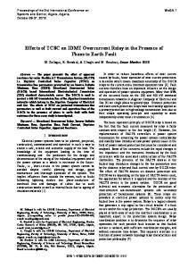
Three phase definite time or dependent time low-set overcurrent protection
51
Three phase instantaneous or dependent time high-set overcurrent protection
50
Signal 1
IL2 Definite time low-set earth-fault protection
51 N
Instantaneous or definite time high-set earth-fault protection
50 N
Signal 2
IL3
Io
Blocking or reset
Start 1
Remote reset, remote setting control or blocking input for the different current stages
Start 2
Circuit breaker failure protection
IRF
51BF
Serial I/O Serial communication port
Fig. 1. Protective functions of the overcurrent and earth-fault relay SPAJ 141 C. 3
Connection diagram
1
7 5A 1A
1A 0.2 A
70
- (~)
L1 L2 L3
74
75
START 1
U aux
SGR3/1
+ (~)
72
SGR3/2
IRF 71
+
I
0
-
0
I
-
TRIP
+
SIGNAL 2
+
SIGNAL 1
65 66
+
START 2
68 69
+
80 81
+
77 78
B
A
SGR2/8
62 61
C
1
+
SGR1/8
D
LATCHING SGB/6 SGB/7
SGR1/2 SGR1/4
TS2
SGR2/4
SS3
SGR2/2
E
SGR1/1
EXTERNAL CONTROL 10
+
SGR2/7
SS2
SGR2/3
11
+
SGR3/3
8 9 25 27 28
F
SGR3/8
SS1
SGR3/7
TS1
1
SGR1/6
1
SGR2/6
1
T1 T3 T5
T7
SGR2/1 0.1...1s
SGR2/5
1
SGF/4
SGR1/7
5 6
IRF
T9
SGR1/3
~ + -
3I>
I/O
SGR3/6
23 4
U2
U1
3I>> Io> Io>> RC SETTINGS RESET
SGR1/5
63
U3
SGB/1
SGB/2
SGB/3
SGB/4 SGB/5 SGB/8
SPA-ZC_
R
Rx
Tx
TRIP
SERIAL PORT
T4
T2
T6 T8
U1
4
SGR3/5
5A 1A
SPAJ 141 C
SGR3/4
5A 1A
Fig. 2. Connection diagram for the combined overcurrent and earth-fault relay SPAJ 141 C with all the relay matrix switchgroups shown.
Uaux A, B, C, D, E, F IRF SGR SGB TRIP SIGNAL 1 SIGNAL 2 START 1 START 2 U1 U3 U2
SPA
Serial Port
T1…T8 SERIAL PORT SPA-ZC_ Rx/Tx
Auxiliary voltage Output relays Self-supervision Switchgroups for the configuration of trippings and signallings Switchgroup for the configuration of the blocking or control signal Trip output relay Signal on overcurrent trip Signal on earth-fault trip Starting or auxiliary trip signal as selected with switchgroup SGR3 Starting of overcurrent low-set stage I> Three-phase overcurrent and non-directional earth-fault module SPCJ 4D24 Input module SPTE 4E2 Power supply and output relay module SPTU 240 R1 or SPTU 48 R1 Starting and tripping indications Serial communication interface Bus connection module Receiver bus terminal (Rx) and transmitter bus terminal (Tx) of the bus connection module
1
61
2
62
69
3
63
77
4
65
5
66
6
74
7
75
8
70
9
71
68
78 80
Made in Finland
81
= 63
25 72 27 10 28 11
Fig. 3. Rear view of relay SPAJ 141 C.
5
Connections
The three phase-currents of the overcurrent protection are connected to terminals 1-2, 4-5 and 7-8, when the rated current of the secondary circuits is In = 5 A. When using current transformers with a rated current of 1 A, terminals 1-3, 4-6 and 7-9 are used. The overcurrent protection may also be used in single-phase or twophase applications, in which case inputs not to be used are left unconnected. In single-phase applications, however, wiring the phase current through two current inputs in series may increase the operating speed of the relay, particularly for instantaneous operations. The neutral current of the earth-fault protection is connected to terminals 25-27 when the rated current is 1 A and to terminals 25-28 when the rated current is 0.2 A. The control input 10-11 can be used in three different ways, as the control input of an external blocking signal for the measuring modules, as the control input for unlatching the trip relay, or as the control input for the remote control of settings. The function is selected by means of switches 1...8 of switchgroup SGB in the main menu of the measuring relay module. The auxiliary supply voltage of the relay is connected to the terminals 61-62. At d.c. auxiliary supply voltage the positive lead is connected to terminal 61. The level of the voltage to be applied to the terminals is determined by the type of power supply and output relay module inserted in the protection. For further details see the description of the power supply module. The auxiliary voltage range of the relay has been marked on the front panel. Output relay A provides the CB tripping commands so that the CB operates once the operating time of the low-set or high-set stage of the overcurrent or non-directional earth-fault module has elapsed. The stages to perform a tripping are selected with switches 2,4,6 and 8 of switchgroup SGR1. On delivery from factory all stages are selected to perform tripping. A latching function of the output relay A can be selected by means of switches SGB 6 and 7 for overcurrent and earth-fault trippings. The trip alarm signals from the measuring modules are obtained through output relays B and C. The signals to be forwarded to the output relays B and C are selected with switches1...8 of switchgroup SGR2 of the measuring module. The switch matrixes for configuration of
6
the control signals of the output relays B and C identical. Normally the output relays B and C are given such a configuration that low-set and high-set overcurrent trip alarm signal is obtained over relay C and the corresponding alarm signal for the earth-fault trips via output relay B. This is also the default setting on delivery. The starting signals from the protective stages of the relay are received through output relay D. The signals to be forwarded to the output relay D are selected by means of switches 1, 3, 5 and 7 of switchgroup SGR1 which is found in the main menu of the measuring module. The starting signals of the low-set and high-set stage of the overcurrent unit are selected with switches 1 and 3, whereas switches 5 and 7 convey the corresponding signals of the non-directional earth-fault unit. Output relay E, terminals 74-75, is a heavy duty output relay capable of controlling a circuit breaker, like the main trip relay A. Relay E is used mainly for bringing out any starting or time delayed signal for starting of auto-reclosures, for signalling or counting purposes or for auxiliary trip. Output relay E is also used as a tripping output for the circuit breaker failure protection, CBFP when the CBFP function is used. In this case the trip signal can be used either to control a circuit breaker upstreams or to control a second trip coil on the main circuit breaker to give a higher redundancy to the breaker operation. Output relay F, terminals 70-71-72, operates as the output relay of the self-supervision system of the relay. The relay operates on the closedcircuit principle so that in normal service conditions the contact gap 70-72 is closed. If a fault is detected by the self-supervision system, or if there is a failure in the auxiliary supply, the output relay drops off providing an alarm signal by closing the NO contact 71-72. The relay is interfaced with a data transmission bus through a 9-pole, D-type subminiature connector located at the rear panel of the relay. By means of bus connection modules SPA-ZC 17 or SPA-ZC 21, the overcurrent and earth-fault relay can be linked to the fibre-optic bus. The terminals of the fibre-optic cables are connected to the counter terminals Rx and Tx of the bus connection module. The fibre-optic cables are linked from one protection to another and to the substation level communication unit, for instance type SRIO 1000M.
Control signals between the modules
The figure below schematically illustrates how the starting, tripping, control and blocking sig-
IL1
I>
t>, k
IL2
nals can be programmed to obtain the required function of the protection.
SGR3 / 1 SGR1 / 1 SGR3 / 2 SGR2 / 1 SGR2 / 2 SGR1 / 2
IRF
SGR3 / 3
IL3
SGB / 1
I>>
t>>
SGR1 / 3 SGF2 / 7 SGR3 / 4 SGR2 / 3 SGR2 / 4 SGR1 / 4
SGB / 6
TS1
1
RESET+ PROGRAM
SS1
SGF2 / 8
Io SGB / 3
Io>>
to>>
D
SIGNAL 1
C
SIGNAL 2
B
TRIP
A
(AR3)
SGR3 / 5 SGR1 / 5 SGR3 / 6 SGR2 / 5 SGR2 / 6 SGR1 / 6
SGR3 / 7 SGR1 / 7 SGR3 / 8 SGR2 / 7 SGR2 / 8 SGR1 / 8
START 2
0.1...1s
SS2
to>
E
(AR2)
SGF1 / 4
1
Io>
START 1
F
1
SGB / 2
BS
IRF
SS3 (AR1)
SGB / 7
RESET+ PROGRAM
TS2
1
1 TRIP RESET
SGB / 4 SGB / 5 SGB / 8
REMOTE SETTINGS RELAY RESET
SPCJ 4D24
SPTU ___R1
Fig. 4. Control signals between the modules of the overcurrent and earth-fault relay SPAJ 141 C. The functions of the blocking and starting signals are selected with the switches of switchgroups SGF, SGB and SGR. The checksums of the switchgroups, are found in the setting menu
Signal abbreviations used
IL1, IL2, IL3 I0 BS SS1 SS2 SS3 TS1 TS2 BS AR1...3 IRF SGF SGB SGR IRF Rx/Tx
of the measuring relay module. The functions of the different switches are explained in the user´s manual of the measuring module SPCJ 4D24.
Phase currents to be measured Neutral current Blocking or control Signal Starting Signal 1 Starting Signal 2 Starting Signal 3 Tripping Signal 1 Tripping Signal 2 Blocking Signal Auto-Reclose starting signals (not in use in SPAJ 141 C) Internal Relay Fault signal Switch Group for Functions Switch Group for Blockings Switch Group for Relay configuration Internal Relay Fault Receiver/Transmitter channel
7
Operation indicators
3I > I
2 I n = 1A 5A (I ) I n = 0.2A 1A (I o )
f n = 50 / 60 Hz
I
5
L1
I
L2
I
L3
I o IRF
SPAJ 141 C 80...265V – ~ 18...80V –
I >/I n
U aux
RESET STEP
t > [ s] k
SPCJ 4D24
I >> / I n
REGISTERS
0
1 2 3 4 5 6 7 8 9
0
0
OPER.IND.
/I n /I n I L3 / I n I
L1
I
L2
I max (15min) /I n
t (I > )[ % ] t (I >>)[ % ] I o[ %I n] t (I o > )[ % ] t (I o >>)[ % ]
t >> [s]
0
0
1 2 3 4 5 6 7 8 9
I o >[ %I n ]
I >START
t o > [s ]
I >TRIP I >> START I >> TRIP
I o >> [ % I n ]
I o >START
t o >>[s] PROGRAM
I o >TRIP
SGF
I o >>START I o >>TRIP CBFP
SGB SGR
Ser.No.
Indication
Explanation
1 2 3 4 5 6 7 8 9
I> START I> TRIP I>> START I>> TRIP I0> START I0> TRIP I0>> START I0>> TRIP CBFP
0085A
0084A
TRIP
RS 611
SPCJ 4D24
B) If the display is dark when one of the protective stages I>, I>>, I0> or I0>> call for a tripping, the faulty phase or the neutral path is indicated with a yellow LED. If, for instance, the TRIP indicator glows red, and the indicators IL1 and IL2 at the same time are illuminated, overcurrent has occurred on phase L1 and L2. C) Besides being a code number at data presentation, the leftmost red digit or the display serves as a visual opetarion indicator. An operation indicator is recognized by the fact that the red digit alone is switched on. The following table named OPERATION IND. on the relay front panel is a key to the function code numbers used.
= The low-set stage I> of the overcurrent unit has started = The low-set stage I> of the overcurrent unit has tripped = The high-set stage I>> of the overcurrent unit has started = The high-set stage I>> of the overcurrent unit has tripped = The low-set stage I0> of the earth-fault unit has started = The low-set stage I0> of the earth-fault unit has tripped = The high-set stage I0>> of the earth-fault unit has started = The high-set stage I0>> of the earth-fault unit has tripped = Circuit Breaker Failure Protection has operated
D) The TRIP indications persist when the protective stage returns to normal. The indicator is reset by pushing the RESET/STEP push-button. Further, the indicators may be reset via the external control input 10-11 by applying a control voltage to the input, provided that the switch SGB/8 is in position 1. The basic protective relay functions are not depending on the state of the operation indicators, reset or non-reset. The relay is permanently operative. If a protective stage starts, but no tripping occurs because the energizing quantity goes below the starting level before the delay circuit times out, the starting indicators are normally automatically switched off. However, by means of the switches SGF2/1…4 the starting indications may be made persistant which means that they are to be reset by pushing the RESET/ STEP push-button.
8
A) The indicator TRIP is lit when one of the protective stages operate. When the protective stage resets, the red indicator remains lit.
The persistent indications are obtained through the following programming. Switch SGF2/1 = 1 Starting indication on I> persistent Switch SGF2/2 = 1 Starting indication on I>> persistent Switch SGF2/3 = 1 Starting indication on I0> persistent Switch SGF2/4 = 1 Starting indication on I0>> persistent On delivery from the factory the switches SGF2/ 1…4 have the preset configuration 0. E) Shortly after the internal self-supervision system has detected a permanent relay fault the red IRF indicator is switched on and the output relay of the self-supervision system operates. Further, in most fault situations a autodiagnostic fault code is shown in the display. The fault code is composed of a red figure 1 and a green code number which indicates what may be the fault type. The fault code persists until the STEP/ RESET button is pressed. When a fault code appears on the display, the code number should be recorded and stated when service is ordered.
Power supply and output relay module
To be able to operate the relay needs a secured auxiliary voltage supply. The power supply module forms the voltages required by the measuring relay module and the auxiliary relays. The withdrawable power supply and output relay module is located behind the system front panel, which is fixed by means of form cross-slotted screws. The power supply and output relay module contains the power supply unit, all output relays, the control circuits of the output relays and the electronic circuitry of the external control inputs. The power supply and output relay module can be withdrawn after removing the system front
panel. The primary side of the power supply module is protected with a fuse, F1, located on the PCB of the module. The fuse size is 1 A (slow). The power supply unit is a transformer connected, i.e. galvanically isolated primary and secondary side, flyback-type dc/dc converter. It forms the dc secondary voltages required by the measuring relay module; that is +24 V, ±12 V and +8 V. The output voltages ±12 V and +24 V are stabilized in the power supply module, while the +5 V logic voltage required by the measuring relay module is formed by the stabilizer of the relay module.
+8V
1 A slow Uaux
Unstabilized logics voltage
+12V
80...265 V ac & dc 18...80 V dc
-12V +24V
Operation amplifier voltage Output relay coil voltage
Fig. 5.Voltage levels of the power supply module. A green LED indicator Uaux on the system front panel is illuminated when the power supply module is in operation. The supervision of the voltages supplying the electronics is placed in the measuring module. If a secondary voltage deviates from its rated value by more than 25 %, a selfsupervision alarm will be established. An alarm is also received when the power supply module is withdrawn from the relay case, or when the auxiliary power supply to the relay is interrupted. There are two versions of power supply and output relay modules available. For both types, the secondary sides and the relay configurations are identical, but the input voltage ranges differ.
Insulation test voltage between the primary and secondary side and the protective earth 2 kV, 50 Hz, 1 min Rated power Pn
5W
Voltage ranges of the power supply modules: - SPTU 240 R1 Uaux = 80...265 V dc/ac - SPTU 48 R1 Uaux = 18...80 V dc (on request ) The SPTU 240 R1 module can be used with both ac and dc voltages. SPTU 48 R1 is designed for dc supply only. The system front panel of the relay indicates the auxiliary voltage range of the power supply module of the relay assembly.
9
Technical data (modified 2002-04)
Energizing inputs Rated current In Overcurrent unit Earth-fault unit Thermal withstand capability - continuously - for 1 s Dynamic current withstand, half-wave value Input impedance Rated frequency fn Rated frequency on request
Output contact ratings Tripping contacts Terminals - Rated voltage - Carry continuously - Make and carry for 0.5 s - Make and carry for 3.0 s - Breaking capacity for dc, when the control circuit time-constant L/R < 40 ms, at 48 / 110 / 220 V dc
0.2 A 2A 50 A 100 A > Setting range Operating time t>>
0.5...5.0 x In 0.05...300 s Extremely inverse Very inverse Normal inverse Long-time inverse RI-type inverse RXIDG-type inverse 0.05...1.0 0.5...40 x In and ∞ 0.04...300 s
Note! If the setting is higher than 2.5 x In, the maximum continuous carry (4 x In) and the levelling out of the IDMT-curves at high current levels must be noted. Note! The high-current end of any inverse time characteristic is determined by the high-set stage which, when started, inhibits the low-set stage operation. The trip time is thus equal to the set t>> for any current higher than I>>. In order to get a trip signal, the stage I>> must also of course be linked to a trip output relay. Earth-fault unit of SPCJ 4D24 Low-set neutral overcurrent stage I0> Setting range Selectable modes of operation - definite time operation - operating time t0>
1.0...25.0 % In
High-set neutral overcurrent stage I0>> Setting range Operating time t0>>
2...200 % In and ∞ 0.05... 300 s
Data transmission Transmission mode Data code Selectable data transfer rates
Fibre optic serial bus ASCII 4800 or 9600 Bd
Fibre optic bus connection modules with integral power unit - for plastic core cables - for glass fibre cables Fibre optic bus connection modules which are powered from the host relay - for plastic core cables - for glass fibre cables
0.05...300 s
SPA-ZC 17 BB SPA-ZC 17 MM SPA-ZC 21 BB SPA-ZC 21 MM
11
Insulation Tests *) Dielectric test IEC 60255-5 Impulse voltage test IEC 60255-5 Insulation resistance measurement IEC 60255-5 Electromagnetic Compatibility Tests *) High-frequency (1 MHz) burst disturbance test IEC 60255-22-1 - common mode - differential mode Electrostatic discharge test IEC 60255-22-2 and IEC 61000-4-2 - contact discharge - air discharge Fast transient disturbance test IEC 60255-22-4 and IEC 61000-4-4 - power supply - I/O ports Environmental conditions Specified ambient service temperature range Long term damp heat withstand according to IEC 60068-2-3 Transport and storage temperature range Degree of protection by enclosure of the relay case as per IEC 60529 when panel mounted Mass of the relay, when flush mounted
2 kV, 50 Hz, 1 min 5 kV, 1.2/50 µs, 0.5 J >100 MΩ, 500 Vdc
2.5 kV 1.0 kV 6 kV 8 kV 4 kV 2 kV
-10...+55°C < 95 % at 40°C for 56 d -40...+70°C IP 54 3.5 kg
*) The tests do not apply to the serial port, which is used exclusively for the bus connection module.
12
Maintenance and repair
When the protective relay is operating under the conditions specified in the section "Technical data", the relay is practically maintenancefree. The relay modules include no parts or components subject to an abnormal physical or electrical wear under normal operating conditions. If the environmental conditions at the relay operating site differ from those specified, as to temperature, humidity, or if the atmosphere around the relay contains chemically active gases or dust, the relay ought to be visually inspected in association with the relay secondary test or whenever the relay modules are withdrawn from the case. At the visual inspection the following things should be noted: - Signs of mechanical damage on relay modules, contacts and relay case - Accumulation of dust inside the relay cover or case; remove by blowing air carefully - Rust spots or signs of erugo on terminals, case or inside the relay
Spare parts
On request, the relay can be given a special treatment for the protection of the printed circuit boards against stress on materials, caused by abnormal environmental conditions. If the relay fails in operation or if the operating values remarkably differ from those of the relay specifications, the relay should be given a proper overhaul. Minor measures can be taken by personnel from the instrument work-shop of the customer's company, e.g. replacement of auxiliary relay modules. All major measures involving overhaul of the electronics are to be taken by the manufacturer. Please contact the manufacturer or his nearest representative for further information about checking, overhaul and recalibration of the relay. Note! Static protective relays are measuring instruments and should be handled with care and protected against moisture and mechanical stress, especially during transport.
Three-phase overcurrent and earth-fault module
SPCJ 4D24
Power supply and output relay module Uaux = 80...265 V ac/dc Uaux = 18...80 V dc
SPTU 240 R1 SPTU 48 R1
Input module
SPTE 4E2
Bus connection module
SPA-ZC 17__ or SPA-ZC 21__
13
Dimensions for mounting
The relay is housed in a normally flush-mounted case. The relay can also be arranged for semiflush mounting with the use of a 40 mm, 80 mm or 120 mm raising frame, which reduces the depth behind the panel by the same dimension. The type designations of the raising frames are SPA-ZX 111 for the 40 mm frame, SPA-ZX 112 for the 80 mm frame and SPA-ZX 113 for the 120 mm frame. A surface mounting case SPAZX 110 is also available. The relay case is made of profile aluminium and finished in beige. A cast aluminium alloy mounting frame with a rubber gasket provides a degree of protection by enclosure to IP 54 between the relay case and the panel surface when the relay is panel mounted.
The relay case is complete with a hinged gasketed, clear, UV-stabilized polycarbonate cover with a sealable fastening screw. The degree of protection by enclosure of the cover is also IP 54. A terminal strip and two multipole connectors are mounted on the back of the relay case to facilitate all input and output connections. To each heavy duty terminal, i.e. measuring input, power supply or trip output, one 6 mm2, one 4 mm2 or one or two 2.5 mm2 wires can be connected. No terminal lugs are needed. The signalling outputs are available on a six pole detachable connector and the serial bus connection is using a 9-pin D-type connector.
142
162 139 ±1
129 ±1
a
b
Panel cut-out
Raising frame SPA-ZX 111 SPA-ZX 112 SPA-ZX 113
14
34
136
30
250 216 186
a
b
176 136 96
74 114 154
Ordering information
When ordering, please, state: 1. Type designation 2. Rated frequency 3. Auxiliary supply 4. Ordering number 5. Accessories - Bus connection module - Fibre-optic cable - Fibre-optic cable
Example SPAJ 141 C fn = 50 Hz Uaux = 110 V dc RS 611 007 - AA SPA-ZC 21 BB SPA-ZF AA5, 2 pces SPA-ZF AA20, 5 pces
Ordering numbers for SPAJ 141 C Type designation
Name
Order number
SPAJ 141 C
Combined overcurrent and earth-fault relay
RS 611 007 - AA, -CA, -DA, -FA
SPAJ 141 C + RTXP 18
Combined overcurrent and earth-fault relay including a test socket RTXP 18 mounted on bars and prewired to the relay
RS 611 207 - AA, -CA, -DA, -FA
The two last letters of the ordering number designate the rated frequency fn and the range of the auxiliary voltage Uaux of the relay as follows: AA equals fn = 50 Hz and Uaux = 80…265 V ac/dc CA equals fn = 50 Hz and Uaux = 18…80 V dc DA equals fn = 60 Hz and Uaux = 80…265 V ac/dc FA equals fn = 60 Hz and Uaux = 18…80 V dc
15
General characteristics of D-type relay modules User´s manual and Technical description
3I >
Fastening screw
I I
Indicators for measured quantities
L1
I
L2
I
L3
I o IRF
Relay symbol Self-supervision alarm indicator (Internal Relay Fault) Display, 1 + 3 digits
I >/I n
RESET STEP
t > [s]
Reset / Step push-button
k
I >> / I n
t >> [s]
Indicators for setting parameters
I o >/ I n
t o > [s] ko I o >> /I n
t o >>[s] PROGRAM
SGF
Indicators for switchgroups SGF, SGB and SGR
Programming push-button
SGB SGR
Fastening screw
879B
TRIP
SPCJ 4D29
Trip indicator Module type designation
1MRS 750066-MUM EN Issued 95-04-12 Version A (replaces 34 SPC 3 EN1) Checked JH Approved TK
General characteristics of D type relay modules
Data subject to change without notice
Contents
2
Front panel lay-out ......................................................................................................... 1 Control push buttons ..................................................................................................... 3 Display ........................................................................................................................... 3 Display main menu ................................................................................................... 3 Display submenus ..................................................................................................... 3 Selector switchgroups SGF, SGB, SGR .......................................................................... 4 Settings ........................................................................................................................... 4 Setting mode ............................................................................................................. 4 Example 1: Setting of relay operation values .............................................................. 7 Example 2: Setting of relay switchgroups................................................................... 9 Recorded information ................................................................................................... 11 Trip test function ......................................................................................................... 12 Example 3: Forced activation of outputs ................................................................. 13 Operation indicators ..................................................................................................... 15 Fault codes.................................................................................................................... 15
Control push-buttons
The front panel of the relay module contains two push buttons. The RESET / STEP push button is used for resetting operation indicators and for stepping forward or backward in the display main menu or submenus. The PROGRAM push button is used for moving from a
certain position in the main menu to the corresponding submenu, for entering the setting mode of a certain parameter and together with the STEP push button for storing the set values. The different operations are described in the subsequent paragraphs in this manual.
Display
The measured and set values and the recorded data are shown on the display of the protection relay module. The display consists of four digits. The three green digits to the right show the measured, set or recorded value and the leftmost red digit shows the code number of the register. The measured or set value displayed is indicated by the adjacent yellow LED indicator on the front panel. When a recorded fault value is being displayed the red digit shows the number of the corresponding register. When the display functions as an operation indicator the red digit alone is shown.
When the auxiliary voltage of a protection relay module is switched on the module initially tests the display by stepping through all the segments of the display for about 15 seconds. At first the corresponding segments of all digits are lit one by one clockwise, including the decimal points. Then the center segment of each digit is lit one by one. The complete sequence is carried out twice. When the test is finished the display turns dark. The testing can be interrupted by pressing the STEP push button. The protection functions of the relay module are alerted throughout the testing.
Display main menu
Any data required during normal operation are accessible in the main menu i.e. present measured values, present setting values and recorded parameter values.
From a dark display only forward movement is possible. When the STEP push button is pushed constantly, the display continuously moves forward stopping for a while in the dark position.
The data to be shown in the main menu are sequentially called up for display by means of the STEP push button. When the STEP push button is pressed for about one second, the display moves forward in the display sequence. When the push button is pressed for about 0.5 seconds, the display moves backward in the display sequence.
Unless the display is switched off by stepping to the dark point, it remains lit for about 5 minutes from the moment the STEP push button was last pushed. After the 5 minutes' time-out the dispaly is switched off.
Less important values and values not very often set are displayed in the submenus. The number of submenus varies with different relay module types. The submenus are presented in the description of the concerned protection relay module.
the display moves forward when the STEP push button is pushed for one second and backward when it is pushed for 0.5 seconds. The main menu has been re-entered when the red display turns dark.
Display submenus
A submenu is entered from the main menu by pressing the PROGRAM push button for about one second. When the push button is released, the red digit of the display starts flashing, indicating that a submenu has been entered. Going from one submenu to another or back to the main menu follows the same principle as when moving from the main menu display to another;
When a submenu is entered from a main menu of a measured or set value indicated by a LED indicator, the indicator remains lit and the address window of the display starts flashing. A submenu position is indicated by a flashing red address number alone on the dispaly without any lit set value LED indicator on the front panel.
3
Selector switchgroups SGF, SGB and SGR
Part of the settings and the selections of the operation characteristic of the relay modules in various applications are made with the selector switchgroups SG_ . The switchgroups are software based and thus not physically to be found in the hardware of the relay module. The indicator of the switchgroup is lit when the checksum of the switchgroup is shown on the display. Starting from the displayed checksum and by entering the setting mode, the switches can be set one by one as if they were real physical switches. At the end of the setting procedure, a checksum for the whole switchgroup is shown. The checksum can be used for verifying that the switches have been properly set. Fig. 2 shows an example of a manual checksum calculation. When the checksum calculated according to the example equals the checksum indicated on the display of the relay module, the switches in the concerned switchgroup are properly set.
Settings
Most of the start values and operate times are set by means of the display and the push buttons on the front panel of the relay modules. Each setting has its related indicator which is lit when the concerned setting value is shown on the display. In addition to the main stack of setting values most D type relay modules allow a second stack of settings. Switching between the main settings
Setting mode
Generally, when a large number of settings is to be altered, e.g. during commissioning of relay systems, it is recommended that the relay settings are entered with the keyboard of a personal computer provided with the necessary software. When no computer nor software is available or when only a few setting values need to be altered the procedure described below is used. The registers of the main menu and the submenus contain all parameters that can be set. The settings are made in the so called setting mode, which is accessible from the main menu or a submenu by pressing the PROGRAM push button, until the whole display starts flashing. This position indicates the value of the parameter before it has been altered. By pressing the PROGRAM push button the programming sequence moves forward one step. First the rightmost digit starts flashing while the rest of the display is steady. The flashing digit is set by means of the STEP push button. The flashing
4
Switch No
Pos.
1 2 3 4 5 6 7 8
1 0 1 1 1 0 1 0
Weigth
Value
x x x x x x x x
1 2 4 8 16 32 64 128
= = = = = = = =
1 0 4 8 16 0 64 0
Checksum
∑
=
93
Fig. 2. Example of calculating the checksum of a selector switchgroup SG_. The functions of the selector switches of the different protection relay modules are described in detail in the manuals of the different relay modules. and the second settings can be done in three different ways: 1) By command V150 over the serial communication bus 2) By an external control signal BS1, BS2 or RRES (BS3) 3) Via the push-buttons of the relay module, see submenu 4 of register A.
cursor is moved on from digit to digit by pressing the PROGRAM push button and in each stop the setting is performed with the STEP push button. After the parameter values have been set, the decimal point is put in place. At the end the position with the whole display flashing is reached again and the data is ready to be stored. A set value is recorded in the memory by pressing the push buttons STEP and PROGRAM simultaneously. Until the new value has been recorded a return from the setting mode will have no effect on the setting and the former value will still be valid. Furthermore any attempt to make a setting outside the permitted limits for a particular parameter will cause the new value to be disqualified and the former value will be maintained. Return from the setting mode to the main menu or a submenu is possible by pressing the PROGRAM push button until the green digits on the display stop flashing.
NOTE! During any local man-machine communication over the push buttons and the display on the front panel a five minute time-out function is active. Thus, if no push button has been pressed during the last five minutes, the relay returns to its normal state automatically. This means that the display turns dark, the relay escapes from a display mode, a programming routine or any routine going on, when the relay is left untouched. This is a convenient way out of any situation when the user does not know what to do. Before a relay module is inserted into the relay case, one must assure that the module has been given the correct settings. If there however is
MAIN MENU
any doubt about the settings of the module to be inserted, the setting values should be read using a spare relay unit or with the relay trip circuits disconnected. If this cannot be done the relay can be sett into a non-tripping mode by pressing the PROGRAM push button and powering up the relay module simultaneously. The display will show three dashes "- - -" to indicate the nontripping mode. The serial communication is operative and all main and submenues are accessible. In the non-tripping mode unnecessary trippings are avoided and the settings can be checked. The normal protection relay mode is entered automatically after a timeout of five minutes or ten seconds after the dark display position of the main menu has been entered.
SUBMENU
SETTING MODE
REV. STEP 0,5 s FWD.STEP 1 s
STEP 0,5 s
PROGRAM 1 s
PROGRAM 5 s
PROGRAM 5 s
Normal status, display off
First measuring value
REV. STEP 0,5 s INCREASE VALUE STEP 0,5 s
Last measuring value
FWD.STEP 1 s
Actual setting value 1
1
Main setting value for stage 1
Actual setting value 2
2
Second setting value for stage 1
Memorized values etc.
1
0
0
0
MOVE FIGURE OR DECIMAL POINT CURSOR WITH BUTTON PROGRAM 1 s
STORE NEW SETTING BY PRESSING STEP AND PROGRAM SIMULTANEOUSLY WHEN THE VALUE IS READY AND THE WHOLE DISPLAY IS BLINKING
NOTE! IN MOST MENU CHARTS THE SUBMENUS HAVE BEEN DRAWN IN A HORIZONTAL DIRECTION IN ORDER TO GET ALL MAIN AND SUBMENU POSITIONS SHOWN IN THE SAME CHART.
Fig.3. Basic principles of entering the main menus and submenus of a relay module.
5
MAIN MENU
SUBMENUS STEP 0.5 s
PROGRAM 1 s
Normal status, display off Current on phase L1
Current on phase L2
Current on phase L3 REV. STEP 0.5 s
Neutral current Io
Actual start value I>
1
Main setting value for I>
2
Second setting value for I>
Actual operate time t> or multiplier k for stage I>
1
Main setting value for t> or k
2
Second setting value for t> or k
Actual start value I>>
1
Main setting value for I>>
2
Second setting value for I>>
Actual operate time t>> of stage I>>
1
Main setting value for t>>
2
Second setting value for t>>
Actual start value Io>
1
Main setting value for Io>
2
Second setting value for Io>
Actual operate time to> or multiplier ko
1
Main setting value for to> or ko
2
Second setting value for to> or ko
M A I N
Actual start value Io>>
1
Main setting value for Io>>
2
Second setting value for Io>>
Actual operate time to>>
1
Main setting value for to>>
2
Second setting value for to>>
M E N U
Actual setting of functional switchgroup SGF1
1 Main setting of SGF1 checksum
2
Main setting of SGF2 checksum
Actual setting of blocking switchgroup SGB
1
Main setting of SGB checksum
2
Second setting of SGB checksum
Actual setting of relay switchgroup SGR1
1
Main setting of SGR1 checksum
2
Main setting of SGR2 checksum
1
Latest memorized, event (n) value of phase L1
1 Event (n-1) value of phase L1
2 Event (n-2) value of phase L1
2
Latest memorized, event (n) value of phase L2
1 Event (n-1) value of phase L2
2
Event (n-2) value of phase L2
3
Latest memorized, event (n) value of phase L3
1 Event (n-1) value of phase L3
2
Event (n-2) value of phase L3
4
Maximum demand current value for 15 minutes
1 Highest maximum demand value found
R E V. S T E P .5 s
F W D. S T E P
FWD. STEP 1 s SUBMENUS
1 s
Fig. 4.Example of part of the main and submenus for the settings of the overcurrent and earth-fault relay module SPCJ 4D29. The settings currently in use are in the main manu and they are displayed by pressing the STEP push button. The main menu also includes the measured current values, the registers 1...9, 0 and A. The main and second setting values are located in the submenus and are called up on the display with the PROGRAM push button.
6
Example 1
Operation in the setting mode. Manual setting of the main setting of the start current value I> of an overcurrent relay module. The initial value a) Press push button STEP repeatedly until the LED close to the I> symbol is lit and the current start value appears on the display. b) Enter the submenu to get the main setting value by pressing the PROGRAM push button more than one second and then releasing it. The red display digit now shows a flashing number 1, indicating the first submenu position and the green digits show the set value. c) Enter the setting mode by pressing the PROGRAM push button for five seconds until the display starts flashing.
d) Press the PROGRAM push button once again for one second to get the rightmost digit flashing.
e) Now the flashing digit can be altered. Use the STEP push button to set the digit to the desired value.
f) Press the PROGRAM push button to make the middle one of the green digits flash.
g) Set the middle digit with of the STEP push button.
for the main setting is 0.80 x In and for the second setting 1.00 x In. The desired main start value is 1.05 x In. RESET STEP
5x1s
0. 8 0
PROGRAM
1s
1 0. 8 0 PROGRAM
5s
1 0. 8 0
1s
1 0. 8 0
5x
1 0. 8 5
PROGRAM
RESET STEP
PROGRAM
1s
1 0. 8 5
RESET STEP
2x
1 0. 0 5 h) Press the PROGRAM push button to make the leftmost green digit flash.
PROGRAM
1s
1 0. 0 5 7
i) Set the digit with the STEP push button.
j) Press the PROGRAM push button to make the decimal point flash.
k) If needed, move the decimal point with the STEP push button.
l) Press the PROGRAM push button to make the whole display flash. In this position, corresponding to position c) above, one can see the new value before it is recorded. If the value needs changing, use the PROGRAM push button to alter the value. m) When the new value has been corrected, record it in the memory of the relay module by pressing the PROGRAM and STEP push buttons simultaneously. At the moment the information enters the memory, the green dashes flash once in the display, i.e. 1 - - -.
n) Recording of the new value automatically initiates a return from the setting mode to the normal submenu. Without recording one can leave the setting mode any time by pressing the PROGRAM push button for about five seconds, until the green display digits stop flashing. o) If the second setting is to be altered, enter submenu position 2 of the setting I> by pressing the STEP push button for approx. one second. The flashing position indicator 1 will then be replaced by a flashing number 2 which indicates that the setting shown on the display is the second setting for I>. Enter the setting mode as in step c) and proceed in the same way. After recording of the requested values return to the main menu is obtained by pressing the STEP push button 8
RESET STEP
0x
1 1. 0 5
PROGRAM
1s
1 1. 0 5
RESET STEP
0x
1 1. 0 5
PROGRAM
1s
1 1. 0 5 RESET STEP
1 - - PROGRAM
PROGRAM
5s
RESET STEP
1s
1 1. 0 5
2 1. 0 0
until the first digit is switched off. The LED still shows that one is in the I> position and the display shows the new setting value currently in use by the relay module.
Example 2
Operation in the setting mode. Manual setting of the main setting of the checksum for the switchgroup SGF1 of a relay module. The initial value for the checksum is 000 and the switches a) Press push button STEP until the LED close to the SGF symbol is lit and the checksum appears on the display. b) Enter the submenu to get the main checksum of SGF1 by pressing the PROGRAM push button for more than one second and then releasing it. The red display now shows a flashing number 1 indicating the first submenu position and the green digits show the checksum. c) Enter the setting mode by pressing the PROGRAM push button for five seconds until the display starts flashing.
d) Press the PROGRAM push button once again to get the first switch position. The first digit of the display now shows the switch number. The position of the switch is shown by the rightmost digit. e) The switch position can now be toggled between 1 and 0 by means of the STEP push button and it is left in the requested position 1.
f) When switch number 1 is in the requested position, switch number 2 is called up by pressing the PROGRAM push button for one second. As in step e), the switch position can be altered by using the STEP push button. As the desired setting for SGF1/2 is 0 the switch is left in the 0 position. g) Switch SGF1/3 is called up as in step f) by pressing the PROGRAM push button for about one second.
SGF1/1and SGF1/3 are to be set in position 1. This means that a checksum of 005 should be the final result.
RESET STEP
nx1s
PROGRAM
0 0 0
1s
1 0 0 0 PROGRAM
PROGRAM
5s
1 0 0 0
1x
1 1
0
1x
1 1
1
1s
1 2
0
1s
1 3
0
RESET STEP
PROGRAM
PROGRAM
9
h) The switch position is altered to the desired position 1 by pressing the STEP push button once.
i) Using the same procedure the switches SGF 1/ 4...8 are called up and, according to the example, left in position 0.
RESET STEP
1x
l) Recording the new value automatically initiates a return from the setting mode to the normal menu. Without recording one can leave the setting mode any time by pressing the PROGRAM push button for about five seconds, until the green display digits stop flashing. m) After recording the desired values return to the main menu is obtained by pressing the STEP push button until the first digit is turned off. The LED indicator SGF still shows that one is in the SGF position and that the display shows the new checksum for SGF1 currently in use by the relay module.
10
1
PROGRAM
5x1s
j) In the final setting mode position, corresponding to step c), the checksum based on the set switch positions is shown. k) If the correct checksum has been obtained, it is recorded in the memory by pressing the push buttons PROGRAM and STEP simultaneously. At the moment the information enters the memory, the green dashes flash in the display, i.e.1 - - -. If the checksum is incorrect, the setting of the separate switches is repeated using the PROGRAM and STEP push buttons starting from step d).
1 3
1 0 0 5 RESET STEP
1 - - PROGRAM
PROGRAM
RESET STEP
5s
nx1s
1 0 0 5
0 0 5
Recorded information
The parameter values measured at the moment when a fault occurs or at the trip instant are recorded in the registers. The recorded data, except for some parameters, are set to zero by pressing the push buttons STEP and PROGRAM simultaneously. The data in normal registers are erased if the auxiliary voltage supply to the relay is interrupted, only the set values and certain other essential parameters are maintained in non-volatile registers during a voltage failure. The number of registers varies with different relay module types. The functions of the registers are illustrated in the descriptions of the different relay modules. Additionally, the system front panel of the relay contains a simplified list of the data recorded by the various relay modules of the protection relay. All D type relay modules are provided with two general registers: register 0 and register A. Register 0 contains, in coded form, the information about e.g. external blocking signals, status information and other signals. The codes are explained in the manuals of the different relay modules. Register A contains the address code of the relay modul which is reqiured by the serial communication system. Submenu 1 of register A contains the data transfer rate value, expressed in kilobaud, of the serial communication.
Submenu 2 of register A contains a bus communication monitor for the SPAbus. If the protection relay, which contains the relay module, is linked to a system including a contol data communicatoe, for instance SRIO 1000M and the data communication system is operating, the counter reading of the monitor will be zero. Otherwise the digits 1...255 are continuously scrolling in the monitor. Submenu 3 contains the password required for changing the remote settings. The address code, the data transfer rate of the serial communication and the password can be set manually or via the serial communication bus. For manual setting see example 1. The default value is 001 for the address code, 9.6 kilobaud for the data transfer rate and 001 for the password. In order to secure the setting values, all settings are recorded in two separate memory banks within the non-volatile memory. Each bank is complete with its own checksum test to verify the condition of the memory contents. If, for some reason, the contents of one bank is disturbed, all settings are taken from the other bank and the contents from here is transferred to the faulty memory region, all while the relay is in full operation condition. If both memory banks are simultaneously damaged the relay will be be set out of operation, and an alarm signal will be given over the serial port and the IRF output relay
11
Trip test function
Register 0 also provides access to a trip test function, which allows the output signals of the relay module to be activated one by one. If the auxiliary relay module of the protection assembly is in place, the auxiliary relays then will operate one by one during the testing. When pressing the PROGRAM push button for about five seconds, the green digits to the right start flashing indicating that the relay module is in the test position. The indicators of the settings indicate by flashing which output signal can be activated. The required output function is selected by pressing the PROGRAM push button for about one second. The indicators of the setting quantities refer to the following output signals: Setting I> Setting t> Setting I>> Setting t>> etc. No indication
The selected starting or tripping is activated by simultaneous pressing of the push buttons STEP and PROGRAM. The signal remains activated as long as the two push butttons are pressed. The effect on the output relays depends on the configuration of the output relay matrix switches. The self-supervision output is activated by pressing the STEP push button 1 second when no setting indicator is flashing. The IRF output is activated in about 1 second after pressing of the STEP push button. The signals are selected in the order illustrated in Fig. 4.
Starting of stage I> Tripping of stage I> Starting of stage I>> Tripping of stage I>> Self-supervision IRF
IRF
I> TRIP
I> START
I» START
I» TRIP
Io> TRIP
Io> START
Io»START
Io» TRIP
REGISTER 0 PROGRAM 5s
PROGRAM 1s
I>
PROGRAM 1s
t>
PROGRAM 1s
I»
PROGRAM 1s
t»
PROGRAM 1s
PROGRAM 1s
PROGRAM 1s
Io>
PROGRAM 1s
to>
PROGRAM 1s
Io» to»
STEP
STEP & PROGRAM
STEP & PROGRAM
STEP & PROGRAM
STEP & PROGRAM
STEP & PROGRAM
STEP & PROGRAM
STEP & PROGRAM
STEP & PROGRAM
Fig. 5.Sequence order for the selection of output signals in the Trip test mode If, for instance, the indicator of the setting t> is flashing, and the push buttons STEP and PROGRAM are being pressed, the trip signal from the low-set overcurrent stage is activated. Return to the main menu is possible at any stage of the trip test sequence scheme, by pressing the PROGRAM push button for about five seconds.
12
Note! The effect on the output relays then depends on the configuration of the output relay matrix switchgroups SGR 1...3.
Trip test function. Forced activation of the outputs. a) Step forward on the display to register 0. RESET STEP
nx1s
0 0 0 0 b) Press the PROGRAM push button for about five seconds until the three green digits to the right.
3I > I I
L1
I
L2 I
L3
I o IRF
0 0 0 0
PROGRAM I >/I n
5s
RESET STEP
t > [s] k
I >> / I n
t >> [s] I o >/ I n
t o > [s] ko I o >> /I n
t o >>[s] PROGRAM
SGF SGB SGR TRIP 879B
c) Hold down the STEP push button. After one second the red IRF indicator is lit and the IRF output is activated. When the step push button is released the IRF indicator is switched off and the IRF output resets. d) Press the PROGRAM push button for one second and the indicator of the topmost setting start flashing.
SPCJ 4D29
3I > I I
e) If a start of the first stage is required, now press the push-buttons PROGRAM and STEP simultaneously. The stage output will be activated and the output relays will operate according to the actual programming of the relay output switchgroups SGR.
L1
I
L2
I
L3
I >/I n
I o IRF
RESET STEP
0 0 0 0
t > [s] k
I >> / I n
t >> [s] I o >/ I n
t o > [s] ko I o >> /I n
t o >>[s] PROGRAM
SGF SGB
RESET STEP
SGR TRIP 879B
Example 3
SPCJ 4D29
PROGRAM
13
f) To proceed to the next position press the PROGRAM push button for about 1 second until the indicator of the second setting starts flashing. PROGRAM
3I > I I
L1
I
L2 I
L3
I o IRF
0 0 0 0 I >/I n
RESET STEP
t > [s]
1s
k
I >> / I n
t >> [s] I o >/ I n
t o > [s] ko I o >> /I n
t o >>[s] PROGRAM
SGF SGB SGR
879B
TRIP
g) Press the push buttons PROGRAM and STEP simultaneously to activate tripping of stage 1 (e.g. the I> stage of the overcurrent module SPCJ 4D29). The output relays will operate according to the actual programming of the relay switchgroups SGR. If the main trip relay is operated the trip indicator of the measuring module is lit.
SPCJ 4D29
3I > I I
L1
I
L2
I
L3
I o IRF
0 0 0 0 I >/I n
RESET STEP
t > [s] k
I >> / I n
t >> [s] I o >/ I n
RESET STEP
t o > [s] ko I o >> /I n
t o >>[s] PROGRAM
SGF SGB SGR
h) The starting and tripping of the remaining stages are activated in the same way as the first stage above. The indicator of the corresponding setting starts flashing to indicate that the concerned stage can be activated by pressing the STEP and PROGRAM buttons simultaneously. For any forced stage operation, the output relays will respond according to the setting of the relay output switchgroups SGR. Any time a certain stage is selected that is not wanted to operate, pressing the PROGRAM button once more will pass by this position and move to the next one without carrying out any operation of the selected stage.
14
879B
TRIP
PROGRAM
SPCJ 4D29
It is possible to leave the trip test mode at any step of the sequence scheme by pressing the PROGRAM push button for about five seconds until the three digits to the right stop flashing.
Operation indication
A relay module is provided with a multiple of separate operation stages, each with its own operation indicator shown on the display and a common trip indicator on the lower part of the front plate of the relay module. The starting of a relay stage is indicated with one number which changes to another number when the stage operates. The indicator remains glowing although the operation stage resets. The
Fault codes
In addition to the protection functions the relay module is provided with a self-supervision system which continuously supervises the function of the microprocessor, its program execution and the electronics. Shortly after the self-supervision system detects a permanent fault in the relay module, the red IRF indicator on the front panel is lit . At the same time the module puts forward a control signal to the output relay of the self-supervision system of the protection relay. In most fault situations a fault code, indicating the nature of the fault, appears on the display of
indicator is reset by means of the RESET push button of the relay module. An unreset operation indicator does not affect the function of the protection relay module. In certain cases the function of the operation indicators may deviate from the above principles. This is described in detail in the descriptions of the separate modules.
the module. The fault code, which consists of a red figure "1" and a three digit green code number, cannot be removed from the display by resetting. When a fault occurs, the fault code should be recorded and stated when service is ordered. When in a fault mode, the normal relay menus are operative, i.e. all setting values and measured values can be accessed although the relay operation is inhibited. The serial communication is also operative making it possible to access the relay information also from a remote site. The internal relay fault code shown on the display remains active until the internal fault possibly disappears and can also be remotely read out as variable V 169.
15
SPCJ 4D24 Combined overcurrent and earth-fault relay module User´s manual and Technical description
3I > I I
L1
I
L2
I
L3
I >/I n
I o IRF
RESET STEP
t > [ s] k
I >> / I n
t >> [s] I o >[ %I n ]
t o > [s ] I o >> [ % I n ]
t o >>[s] PROGRAM
SGF SGB SGR
0085A
TRIP
SPCJ 4D24
1MRS 750121-MUM EN Issued 1995-09-14 Modified 2002-05-15 Version B (replaces 34 SPCJ 9 EN1) Checked MK Approved OL Data subject to change without notice
SPCJ 4D24 Combined overcurrent and earth-fault relay module
Contents
Features .......................................................................................................................... 2 Description of function .................................................................................................. 3 Block diagram ................................................................................................................. 5 Front panel ..................................................................................................................... 6 Operation indicators ....................................................................................................... 7 Settings ........................................................................................................................... 8 Programming switches .................................................................................................... 9 Measured data............................................................................................................... 13 Recorded information ................................................................................................... 14 Main menus and submenus of settings and registers ..................................................... 16 Time/current characteristics (modified 2002-05) ........................................................... 18 Technical data ............................................................................................................... 26 Serial communication parameters ................................................................................. 27 Fault codes .................................................................................................................... 34
Features
A low-set overcurrent stage I> with a definite time and six inverse time modes of operation A high-set overcurrent stage I>> with a setting range of 0.5...40 x In. The operation of the highset overcurrent stage can be set out of function A low-set neutral overcurrent stage I0> with a setting range of 1.0...25.0 % In and definite time mode of operation A high-set neutral overcurrent stage I0>> with a setting range of 2.0...200 % In. The operation of the high-set neutral over current stage can be set out of function
2
Digital display of measured and set values and sets of data recorded at the moment when faults occur All settings may be keyed in using the pushbuttons of the front panel or they may be set using a personal computer Continuous self-supervision including both hardware and software. At a permanent fault the alarm output relay operates and the other outputs are blocked.
Description of function Overcurrent unit
The overcurrent unit of the combined overcurrent and earth-fault module SPCJ 4D24 is designed for single-phase, two-phase or threephase operation. It contains two overcurrent stages, i.e. a low-set overcurrent stage I> and a high-set overcurrent stage I>>. The low-set or high-set current stage starts if the current on one of the phases exceeds the setting value of the stage concerned. When starting, the concerned stage provides a starting signal SS1 or TS1 and simultaneously the digital display on the front panel indicates starting. If the overcurrent situation lasts long enough to exceed the set operating time, the stage that started calls for a C.B. tripping by providing a tripping signal TS2. At the same time the operation indicator goes on with red light. The red operation indicator remains on although the stage resets. The indicator is reset with the RESET push-button. By proper configuration of the output relay switchgroups an additional auxiliary trip signal TS1 can be generated. The maximum continuous current carrying capacity of the energizing inputs is 4 x In, which must be observed when relay settings are calculated. The operation of the low-set overcurrent stage I> or the high-set overcurrent stage I>> can be blocked by bringing a blocking signal BS to the unit. The blocking configuration is set by means of switchgroup SGB. The operation of the low-set overcurrent stage can be based on a definite time or an inverse time characteristic. The mode of operation is programmed with SGF1/1…3. At definite time mode of operation the operating time t> is directly set in seconds within the setting range, 0.05...300 s. When using inverse time mode of operation (I.D.M.T.) four internationally standardized and two special type time/current characteristics are available. The programming switches SGF1/1...3 are also used for selecting the desired operation characteristic. The operating time t>> of the high-set overcurrent stage is set separately within the range 0.04...300 s.
The operation of the two overcurrent stages is provided with a latching facility (switch SGB/6) keeping the tripping output energized, although the signal which caused the operation disappears. The stages are reset by simultaneous pressing of the push-buttons RESET and PROGRAM, see section "Programming switches". The setting value I>>/In of the high-set overcurrent stage may be subject to automatic doubling when connecting the protected object to the network, i.e. in a starting situation. Thus the setting value of the high-set overcurrent stage may be lower than the connection inrush current. The automatic doubling function is selected with switch SGF1/5. The starting situation is defined as a situation where the phase currents rise from a value below 0.12 x I> to a value exceeding 1.5 x I> in less than 60 ms. The starting situation comes to an end when the currents fall below 1.25 x I>. The setting range of the high-set overcurrent stage is 0.5...40 x In. When selecting a setting in the lower end of the range, the module will contain two almost identical operation stages. In this case the overcurrent unit of the SPCJ 4D24 module may be used for e.g. two-stage load shedding purposes. The operation of the high-set overcurrent stage may be set out of operation by means of switch SGF2/5. When the high-set unit is set out of operation the display shows a "- - -" readout, indicating that the operating value is infinite. Note! At inverse time characteristic the effective setting range of the low-set overcurrent stage is 0.5…2.5 x In, although start current settings within the range 2.5…5.0 x In can be set on the relay. At inverse time characteristic any start current setting above 2.5 x In of the low-set stage will be regarded as being equal to 2.5 x In. Note! The operation of the low-set stage based on inverse time characteristic will be blocked by starting of the high-set stage. Then the operate time of the overcurrent unit is determined by the set operate time of the high-set stage at heavy fault currents.
3
Earth-fault unit
The non-directional earth-fault unit of the module SPCJ 4D24 is a single-pole neutral current or residual current overcurrent unit. It contains two neutral overcurrent stages, i.e. a lowset overcurrent stage I0> and a high-set overcurrent stage I0>>. The low-set or high-set overcurrent stage starts if the current to be measured exceeds the setting value of the stage concerned. When starting, the stage provides a starting signal SS1 or TS1 and simultaneously the operation indicator on the front panel indicates starting. If the earth-fault situation lasts long enough to exceed the set operating time, the stage that started calls for a C.B. tripping by providing a tripping signal TS2. At the same time the red operation indicator of the tripping stage goes on. The operation indicator remains on although the stage resets. The indicator is reset with the RESET push-button. The neutral current measured by the earth-fault unit is filtered in a low-pass filter which effectively reduces the amount of harmonics in the measured signal. For example the third harmonics is reduced to about ten percent of its original value by the filter. Higher order harmonics are reduced even more. The operation of the low-set overcurrent stage I0> or the high-set stage I0>> can be blocked by applying a blocking signal BS onto the stage. The blockings are programmed by means of switchgroup SGB on the front of the plug-in module.
The operation of the low-set neutral current stage I0> is based on a definite time characteristic. The operating time t0> can be set within the setting range 0.05...300 s. The operating time t0>> of the high-set current stage is set separately within the range 0.05… 300 s. The operation of the two neutral overcurrent stages is provided with a latching facility (switch SGB/7) keeping the tripping output energized, although the signal which caused the operation disappears. The stages are reset by simultaneous pressing of the push-buttons RESET and PROGRAM, see section "Programming switches". The operation of the high-set earth-fault stage may be inhibited when connecting the protected object to the network, i.e. when the lowset stage of the overcurrent unit is started. Thus it is possible to avoid malfunction due to virtual earth-fault currents caused by current transformer anomalies in connection with the connection inrush current. The automatic inhibiting function is selected with switch SGF1/6. The operation of the high-set earth-fault stage I0>> may be totally blocked by means of switch SGF2/6. When the high-set stage is set out of operation, the display shows a "- - -" readout, indicating that the setting value is infinite.
Circuit breaker failure protection
The unit is also provided with a circuit breaker failure protection (CBFP), which gives a trip signal via TS1 within a set time 0.1…1 s after the normal trip signal TS2, if the fault has not been cleared within that time. The output contact of the circuit breaker failure protection is normally used for tripping an upstream circuit breaker. The CBFP can also be used to estab-
lish a redundant trip system by using dual trip coils on the circuit breaker and wiring one of them to TS2 and the other one to TS1. The circuit breaker failure protection is selected by means of switch SGF1/4. The setting of the time delay can be made using submenu position five in register A.
Remote settings
All the main setting values may be provided with alternative setting values that can be called up by remote control. The switching between main and remote settings is normally made by utilizing the serial communication link. If the serial
communication is not used, the control input signal BS can be programmed to perform the switching too. Finally manual switching between setting banks can be made using submenu position four in register A.
4
Block diagram SGR3 / 1 SGR1 / 1 50 ms
IL1
t>, k
IL2
SGR2 / 2 SGR1 / 2 SGR3 / 3
SGF1 / 1
IL3
SGR3 / 2 SGR2 / 1
I>
SGR1 / 3
SGF1 / 2 SGF1 / 3
SGB / 1
SGB / 6
1
RESET+ PROGRAM
TS1
SGF2 / 7 40 ms
I>>
SGR3 / 4
1
SGR2 / 3
t>>
SGR2 / 4 SGR1 / 4
SS1
SGB / 2
BS
SGF1 / 5 0.12 x I>
SGF1 / 4
1
2 x I>>
AR2
0.1...1s
SS2
60 ms
&
1.5 x I>
SGF2 / 8
AR3
1.25 x I>
SGR3 / 5 SGR1 / 5 60 ms
Io>
to>, ko
Io
SS3
SGR3 / 6 SGR2 / 5
AR1
SGR2 / 6 SGR1 / 6
SGB / 3
SGR3 / 7 SGR1 / 7 40 ms
Io>>
SGF1 / 6
to>>
SGB / 7
RESET+ PROGRAM
SGR3 / 8 SGR2 / 7 SGR2 / 8
1
TS2
1
SGR1 / 8 TRIP RESET
SGB / 4 SGB / 5 SGB / 8
REMOTE SETTINGS RELAY RESET
SPCJ 4D24
Fig. 1. Block diagram for overcurrent and earth-fault module SPCJ 4D24 IL1, IL2, IL3 I0 BS1 SGF SGB SGR1...3 TS1 SS1 SS2 SS3 TS2 AR1, AR2, AR3 TRIP
Measured phase currents Measured neutral current External blocking or resetting signal Programming switchgroup SGF on the front panel Programming switchgroup SGB on the front panel Programming switchgroups SGR on the front panel Starting signal1 or auxiliary tripping signal depending on programming of switchgroup SGR3 Start signal for stages selected with switchgroup SGR1 Trip signal 1 for stages selected with switchgroup SGR2 Trip signal 2 for stages selected with switchgroup SGR2 Tripping signal from stages selected with switchgroup SGR1 Starting signals to autoreclose unit Red indicator for tripping
Note! All input and output signals of the module are not necessarily wired to the terminals of every relay assembly using this module. The signals
wired to the terminals are shown in the diagram illustrating the flow of signals between the plugin modules of the relay assembly.
5
Front panel 3I > I I
Current measurement indicators for phases L1, L2, L3 and I0
Indicator for starting value setting of stage I> Indicator for setting ofoperating time t> or time multiplier k of stage I> Indicator for starting value setting of stage I>>
L1
I
L2
I
L3
I >/I n
I o IRF
RESET STEP
t > [ s] k
I >> / I n
Indicator for operating time setting of stage I>>
t >> [s]
Indicator for starting value setting of stage I0>
I o >[ %I n ]
Indicator for setting of operating time t0>
t o > [s ]
Indicator for starting value setting of stage I0>>
I o >> [ % I n ]
Indicator for operating time setting of stage I0>>
t o >>[s]
Indicator for switchgroup SGF1..2 checksum
SGF
Indicator for switchgroup SGB checksum
SGB
Indicator for switchgroup SGR1...3 checksum
SGR
PROGRAM
0085A
TRIP
3I > I I
L1
I
L2
I
L3
I o IRF
SPCJ 4D24
Simplified device symbol Self-supervision alarm indicator Display
I >/I n
RESET STEP
t > [ s]
Reset and display step push-button
k
I >> / I n
t >> [s] I o >[ %I n ]
t o > [s ] I o >> [ % I n ]
t o >>[s] PROGRAM
SGF
Programming push-button
SGB SGR
0085A
TRIP
SPCJ 4D24
Trip indicator Type designation of plug-in module
Fig. 2. Front panel of the combined overcurrent and earth-fault module SPCJ 4D24 6
Operation indications
Each overcurrent stage has its own starting indicator and operation indicator shown as a figure in the digital display. Further all stages share a common red LED indicator named "TRIP", which indicates that the module has delivered a tripping signal. The operation indicator in the display remains illuminated when the current stage resets, thus indicating which protection stage was operating. The operation indicator is reset with the Indication 1 2 3 4 5 6 7 8 9
RESET push-button. The function of the plugin module is not affected by an activated operation indicator. If a starting of a stage is short enough not to cause a trip, the starting indication is normally self-reset when the stage is reset. By means of switches SGF2/1…4 if needed, the starting indicators can be programmed for manual resetting. The following table shows the starting and tripping indicators and their meanings.
Explanation I> START I> TRIP I>> START I>> TRIP I0> START I0> TRIP I0>> START I0>> TRIP CBFP
= The low-set stage I> of the overcurrent unit has started = The low-set stage I> of the overcurrent unit has tripped = The high-set stage I>> of the overcurrent unit has started = The high-set stage I>> of the overcurrent unit has tripped = The low-set stage I0> of the earth-fault unit has started = The low-set stage I0> of the earth-fault unit has tripped = The high-set stage I0>> of the earth-fault unit has started = The high-set stage I0>> of the earth-fault unit has started = The circuit breaker failure protection has operated
When one of the protection stages of the module performs a tripping, the indicators for the measured values of the module indicate the faulty phase, i.e. in which phase(s) the current has exceeded the setting value of the stage (so called phase fault indication). If for instance, the operation indicator of the I> stage is switched goes on and the indicators IL1 and IL2 are illuminated, the operation was caused by overcurrent in phases L1 and L2. When pressing the push-button RESET, the phase fault indication disappears.
The self-supervision alarm indicator IRF indicates that the self-supervision system has detected a permanent fault. The indicator is lit with red light shortly after the fault has been detected. At the same time the plug-in module delivers a signal to the self-supervision system output relay of the protection assembly. Additionally, in most fault cases, a fault code showing the nature of the fault appears on the display of the module. The fault code, consisting of a red figure one and a green code number, persists until the STEP/RESET button is pressed. When a fault occurs, the fault code should be recorded and stated when ordering service.
7
Settings
The setting values are shown by the right-most three digits of the display. An indicator close to the setting value symbol shows when illumiI>/In
The operating current of the I> stage as a multiple of the rated current of the protection. Setting range 0.5...5.0 x In at definite time characteristic and 0.5…2.5 x In at inverse time characteristic.
t> k
The operating time of the I> stage, expressed in seconds, when in the definite time mode of operation (SGF1/1-2-3 = 0-0-0). The setting range is 0.05...300 s. At inverse definite minimum time mode of operation the time multiplier k setting range is 0.05...1.00.
I>>/In
The starting current of the I>> stage as a multiple of the rated current of the protection. Setting range 0.5...40.0 x In. Additionally, the setting "infinite" (displayed as n - - -) can be selected, with switch SGF2/5, which makes the stage I>> inoperative.
t>>
The operating time of the I>> stage, expressed in seconds. The setting range is 0.04...300 s
I0>/In
The starting current of the I0> stage as a per cent of the rated current of the protection. Setting range 1.0...25.0 % In.
t 0>
The operating time of the I0> stage, expressed in seconds. The setting range is 0.05...300 s
I0>>/In
The starting current of the I0>> stage as a percent of the rated current of the protection. Setting range 2.0...200% In. Additionally, the setting "infinite" set by switch SGF2/6 (displayed as n - - -) can be selected with switch SGF2/6 which makes the stage I0>> inoperative.
t0>>
The operating time of the I0>> stage, expressed in seconds. The setting range is 0.05...300 s
Further, the checksums of the programming switchgroups SGF1,SGB and SGR1 are indicated on the display when the indicators adjacent to the switchgroup symbols on the front panel are illuminated. The checksums for groups SGF2, SGR2 and SGR3 are found in
8
nated which setting value is indicated on the display.
the submenus of the corresponding first switchgroup. See further clause "Main menus and submenus of settings and registers". An example of calculating the checksum is given in the general description of the D-type SPC relay modules.
Programming switches
Functional switchgroup SGF1
Additional functions required by individual applications are selected by means of the switchgroups SGF, SGB and SGR indicated on the front panel. The numbering of the switches, 1...8, and the switch positions 0 and 1 are indi-
cated when setting the switchgroups. In normal service only the checksums are shown. The switchgroups SGF2, SGR2 and SGR3 are found in the submenus of the switchgroups SGF and SGR.
Switch
Function
SGF1/1 SGF1/2 SGF1/3
Switches SGF1/1...3 are used for selecting the operation characteristic of the lowset overcurrent stage I>, i.e. definite time mode of operation or inverse definite minimum time (I.D.M.T.) mode of operation. At inverse definite minimum time mode of operation the switches are, further, used for selecting the current/time characteristic of the module. SGF1/1 SGF1/2 SGF1/3 0 1 0 1 0 1 0 1
SGF1/4
0 0 1 1 0 0 1 1
0 0 0 0 1 1 1 1
Mode of operation
Characteristics
Definite time I.D.M.T " " " " " "
0.05...300 s Extremely inverse Very inverse Normal inverse Long-time inverse RI-characteristic RXIDG-characteristic Not in use (long-time inverse)
Selection of the circuit breaker failure protection. When SGF1/4 =1 the trip signal TS2 will start a timer which will produce a 0.1…1 s delayed trip signal via TS1, if the fault has not been cleared before. With switch SGF1/4 = 0 only the normal trip signal TS2 is activated.
SGF1/5
Selection of automatic doubling of the setting value of the high-set overcurrent stage when the protected object is energized. When SGF1/5 = 0, no doubling of the setting value I>> is obtained. When SGF1/5 = 1, the setting value of the I>> stage doubles automatically. This makes it possible to give the high-set current stage a setting value below the connection inrush current level.
SGF1/6
High-set stage of the earth-fault protection inhibited by starting of the low-set stage of the overcurrent unit When SGF1/6 = 0, the operation of the high-set earth-fault protection is operating under all phase current conditions When SGF1/6 =1, the earth-fault protection is inhibited if the low-set stage of the overcurrent unit has started
SGF1/7
Reserved for future use
SGF1/8
Reserved for future use
9
Functional switchgroup SGF2
Switch
Function
SGF2/1 SGF2/2 SGF2/3 SGF2/4
Switches SGF2/1...4 are used for selecting the mode of operation of the starting indicators of the different stages. When the switches are in position 0 the starting signals are all automatically reset when the fault is cleared. In order to get a hand reset starting indication for a stage, the corresponding switch is brought into position 1: SGF2/1 = 1 equals manual resetting of the starting indication of stage I> SGF2/2 = 1 equals manual resetting of the starting indication of stage I>> SGF2/3 = 1 equals manual resetting of the starting indication of stage I0> SGF2/4 = 1 equals manual resetting of the starting indication of stage I0>>
SGF2/5
The high-set instantaneous operation of the stage I>> can be set out of operation by means of this switch. When SGF2/5 = 0 the high-set stage I>> is operative When SGF2/5 = 1 the high-set stage I>> is blocked and the display shows "- - -"
SGF2/6
The high-set instantaneous operation of the stage I0>> can be completely set out of operation by means of this switch. When SGF2/6 = 0 the high-set stage I0>> is operative When SGF2/6 = 1 the high-set stage I0>> is blocked and the display shows "- - -"
SGF2/7
The starting signal of the high-set overcurrent stage I>> brought to the auto-reclose signal output AR1 When SGF2/7 = 1, the starting signal of I>> is controlling AR1. Note! The output is equal to SS3, which means that in this case an other signal must not be connected to same output! When SGF2/7 =0, the starting output of I>> is not affecting the output AR1 or SS3. Thus the signal output SS3 is available for other purposes.
SGF2/8
The starting signal from stage I0>- or stage I0>>- brought to auto-reclose signal output AR3 When SGF2/8 = 0 the starting signal from stage I0> is controlling AR3 When SGF2/8 = 1 the starting signal from stage I0>> is controlling AR3
10
Blocking or control input switchgroup SGB
Switch
Function
SGB/1...4
Switches SGB/1...4 are used when the external control signal BS is to be used for blocking one or more of the current stages of the module. When all the switches are in position 0 no stage is blocked. When SGB/1 = 1, the stage I> is blocked by the input signal BS When SGB/2 = 1, the stage I>> is blocked by the input signal BS When SGB/3 = 1, the stage I0> is blocked by the input signal BS When SGB/4 = 1, the stage I0>> is blocked by the input signal BS
SGB/5
This switch enables switching over from the main settings to the second settings and vice versa even without serial communication, using the external control input signal BS. When SGB/5 = 0, the settings are not to be remotely controlled or they are controlled via the serial communication only When SGB/5 = 1, the settings are remotely controlled or via the external input. Main values of the settings are used when there is no control voltage on the input and the second settings are enforced when a control voltage is connected to the control input. Note! Whenever main and second settings are used, care should be taken that the switch SGB/5 has the same position both in the main and second setting bank. Otherwise a conflict situation might occur when switching setting banks by contact or via serial communication.
SGB/6
Selection of a latching feature for the tripping signal TS2 for overcurrent faults. When SGB/6 = 0, the tripping signal returns to its initial state (= the output relay drops off ), when the measuring signal causing the operation falls below the starting level. When SGB/6 = 1, the tripping signal remains on (= the output relay operated), although the measuring signal falls below the starting level. Then the starting signals have to be reset by pressing the push-buttons RESET and PROGRAM simultaneously. 1)
SGB/7
Selection of a latching feature for the trip signal TS2 for earth faults. When SGB/7 = 0, the tripping signal returns to its initial state (= the output relay drops off ), when the measuring signal causing the operation falls below the starting level. When SGB/7 = 1, the tripping signal remains on (= the output relay operated), although the measuring signal falls below the starting level. Then the starting signals have to be reset by pressing the push-buttons RESET and PROGRAM simultaneously. 1)
SGB/8
Remote resetting of a latched output relay. When the output relay with SGB/6 or SGB/7 has been selected to be latching, a remote relay reset can be performed using the control input signal BS when SGB/8 =1. When delivered from factor all switches SGB are set at zero, i.e. the checksum SGB is 0.
1)
From the program version 042D and later versions an additional feature has been incorporated into the relay module SPCJ 4D24.
When the latching function is used the latched output can be reset by pushing the PROGRAM button alone, in which case the stored information of the module is not erased. 11
Output relay matrix switchgroups SGR1, SGR2 and SGR3
SGR1
The switches of switchgroup SGR1 are used to select the protective stages to be brought to the starting signal output SS1 and the tripping signal output TS2.
SGR2
The switches of switchgroup SGR2 are used for configuring the tripping signals of the different protective stages. There are two outputs, SS2 and SS3, to which the signals can be linked.
SGR3
The switches of switchgroup SGR3 are used for configurating the starting and tripping signals to the starting or auxiliary tripping output TS1. Note! If the circuit breaker failure protection has been selected in with switch SGF1/4, it will also utilize the TS1 output.
Switch
Function
SGR1/1
When SGR1/1 = 1, is linked to SS1 When SGR1/2 = 1, is linked to TS2 When SGR1/3 = 1, linked to SS1 When SGR1/4 = 1, linked to TS2 When SGR1/5 = 1, linked to SS1 When SGR1/6 = 1, linked to TS2 When SGR1/7 = 1, linked to SS1 When SGR1/8 = 1, linked to TS2
SGR1/2 SGR1/3 SGR1/4 SGR1/5 SGR1/6 SGR1/7 SGR1/8
Factory Checksum setting value the starting signal of stage I> 1
1
1
2
0
4
1
8
0
16
1
32
0
64
1
128
the tripping signal of stage I> the starting signal of stage I>> is the tripping signal of stage I>> is the starting signal of stage I0> is the tripping signal of stage I0> is the staring signal of stage I0>> is the tripping signal of stage I0>> is
Checksum for factory setting of SGR1 SGR2/1 SGR2/2 SGR2/3 SGR2/4 SGR2/5 SGR2/6 SGR2/7 SGR2/8
When SGR2/1 = 1, linked to SS2 When SGR2/2 = 1, linked to SS3 When SGR2/3 = 1, linked to SS2 When SGR2/4 = 1, linked to SS3 When SGR2/5 = 1, linked to SS2 When SGR2/6 = 1, linked to SS3 When SGR2/7 = 1, linked to SS2 When SGR2/8 = 1, linked to SS3
the tripping signal from stage I> is 1
1
0
2
1
4
0
8
0
16
1
32
0
64
1
128
the tripping signal from stage I> is the tripping signal from stage I>> is the tripping signal from stage I>> is the tripping signal from stage I0> is the tripping signal from stage I0> is the tripping signal from stage I0>> is the tripping signal from stage I0>> is
Checksum for factory setting of SGR2
12
171
165
Switch
Function
SGR3/1
When SGR3/1 = 1, linked to TS1 When SGR3/2 = 1, linked to TS1 When SGR3/3 = 1, linked to TS1 When SGR3/4 = 1, linked to TS1 When SGR3/5 = 1, linked to TS1 When SGR3/6 = 1, linked to TS1 When SGR3/7 = 1, linked to TS1 When SGR3/8 = 1, linked to TS1
SGR3/2 SGR3/3 SGR3/4 SGR3/5 SGR3/6 SGR3/7 SGR3/8
Factory Checksum setting value the starting signal of stage I> is 0
1
0
2
0
4
0
8
0
16
0
32
0
64
0
128
the tripping signal of stage I> is the starting signal of stage I>> is the tripping signal of stage I>> is the starting signal of stage I0> is the tripping signal of stage I0> is the starting signal of stage I0>> is the tripping signal of stage I0>> is
Checksum for factory setting of SGR3
Measured data
The measured values are displayed by the three right-most digits of the display. The currently Indicator
0
measured data are indicated by an illuminated LED indicator on the front panel.
Measured data
IL1
Line current on phase L1 as a multiple of the rated current In (0…63 x In)
IL2
Line current on phase L2 as a multiple of the rated current In (0…63 x In)
IL3
Line current on phase L3 as a multiple of the rated current In (0…63 x In)
I0
Neutral current as a per cent of the rated current In (0…210% In)
13
Recorded information
The left-most red digit displays the register address and the other three digits the recorded information. Register/ STEP
14
A symbol "//" in the text indicates that the following item is found in a submenu.
Recorded information
1
Phase current IL1 measured as a multiple of the rated current of the overcurrent protection. If the overcurrent stage starts or performs a tripping, the current value at the moment of tripping is stored in a memory stack. A new tripping moves the old value up one place in the stack and adds a new value to the stack. At a maximum five values are memorized - if a sixth starting occurs, the oldest value will be lost.
2
Phase current IL2 measured as a multiple of the rated current of the overcurrent protection. If the overcurrent stage starts or performs a tripping, the current value at the moment of tripping is stored in a memory stack. A new tripping moves the old value up one place in the stack and adds a new value to the stack. At a maximum five values are memorized - if a sixth starting occurs, the oldest value will be lost.
3
Phase current IL3 measured as a multiple of the rated current of the overcurrent protection. If the overcurrent stage starts or performs a tripping, the current value at the moment of tripping is stored in a memory stack. A new tripping moves the old value up one place in the stack and adds a new value to the stack. At a maximum five values are memorized - if a sixth starting occurs, the oldest value will be lost.
4
Maximum demand current value for a period of 15 minutes expressed in multiples of the relay rated current In and based on the highest phase current. // Highest maximum demand value found since latest full relay reset.
5
Duration of the latest starting situation of stage I> as a percentage of the set operating time t> or at I.D.M.T. mode of operation the calculated operation time. A new starting resets the counter, which then starts counting from zero and moves the old value up in the memory stack. At a maximum five values are memorized if a sixth starting occurs the oldest value will be lost. When the concerned stage has tripped, the counter reading is 100. // Number of startings of the low-set overcurrent stage I>, n (I>) = 0...255.
6
Duration of the latest starting situation of stage I>> as a percentage of the set operating time t>>. A new starting resets the counter, which then starts counting from zero and moves the old value up in the memory stack. At a maximum five values are memorized - if a sixth starting occurs, the oldest value will be lost. When the concerned stage has tripped, the counter reading is 100. // Number of startings of the high-set overcurrent stage I>>, n (I>>) = 0...255.
7
Neutral overcurrent I0 measured as a per cent of the rated current of the earth-fault protection. If the earth-fault stage starts or performs a tripping, the current value at the moment of tripping is stored in a memory stack. A new tripping moves the old value up one place in the stack and adds a new value to the stack. At a maximum five values are memorized - if a sixth starting occurs, the oldest value will be lost.
Register/ STEP
Recorded information
8
Duration of the latest starting situation of stage I0> as a percentage of the set operating time t0>. A new starting resets the counter, which then starts counting from zero and moves the old value up in the memory stack. At a maximum five values are memorized - if a sixth starting occurs the oldest value will be lost. When the concerned stage has tripped, the counter reading is 100. // Number of startings of the low-set neutral overcurrent stage I0>, n (I0>) = 0...255.
9
Duration of the latest starting situation of stage I0>> as a percentage of the set operating time t0>>. A new starting resets the counter, which then starts counting from zero and moves the old value up in the memory stack. At a maximum five values are memorized - if a sixth starting occurs, the oldest value will be lost. When the concerned stage has tripped, the counter reading is 100. // Number of startings of the high-set neutral overcurrent stage I0>>, n (I0>>) = 0...255.
0
Display of blocking signals and other external control signals. The right-most digit indicates the state of the blocking input of the unit. The following states may be indicated: 0 = no blocking signal 1 = the blocking or control signal BS is active. The effect of the signal on the unit is determined by the setting of switchgroup SGB From this register "0" it is possible to move on to the TEST mode, where the starting and tripping signals of the module are activated one by one. For further details see the description "General characteristics of D-type SPC relay units".
A
The address code of the measuring relay module, required by the serial communication system. The address code is set at zero unless the serial communication system is used. The submenus of this register comprise the selection of the data transfer rate of the serial communication, a bus traffic monitor indicating the operating state of the serial communication system, a password required for the remote control of the settings and a status information for the main/second setting bank, and finally the setting of time delay for the circuit breaker failure protection. If the module is connected to a system including a control data communicator and if the communication system is operating, the counter reading of the bus traffic monitor will be zero. Otherwise the numbers 0...255 are continuously rolling in the counter. The password given in the setting mode of the next submenu step must always be entered via the serial communication before settings can be remotely altered. With the setting selector status in the fourth submenu either the main setting bank or the second setting bank can be made active.
-
Display dark. By pressing the STEP push-button the beginning of the display sequence is re-entered.
The registers 1...9 are set to zero by pressing the push-buttons RESET and PROGRAM simultaneously. The registers are also cleared if the auxiliary power supply of the module is interrupted. The address code of the plug-in module, the data transfer rate of the serial commu-
nication, the password and the status of the main/second setting bank switch are not erased by a voltage failure. The instructions for setting the address and the data transfer rate are described in the "General characteristics of D-type SPC relay units".
15
Main menus and submenus of settings and registers MAIN MENU
SUBMENUS STEP 0.5 s
PROGRAM 1 s
Normal status, display off Current on phase L1
Current on phase L2
Current on phase L3 Neutral current Io
REV. STEP 0.5 s
Actual starting value I>
1
Main setting value for I>
2
Second setting value for I>
Actual operating time t> or multiplier k for stage I>
1
Main setting value for t> or k
2
Second setting value for t> or k
Actual starting value I»
1
Main setting value for I»
2
Second setting value for I»
Actual operating time t» of stage I»
1
Main setting value for t»
2
Second setting value for t»
Actual starting value Io>
1
Main setting value for Io>
2
Second setting value for Io>
Actual operating time to> or multiplier ko
1
Main setting value for to> or ko
2
Second setting value for to> or ko
M A I N
Actual starting value Io»
1
Main setting value for Io»
2
Second setting value for Io»
Actual operating time to»
1
Main setting value for to»
2
Second setting value for to»
M E N U
Actual setting of functional switchgroup SGF1
1 Main setting of SGF1checksum
2
Main setting of SGF2checksum
Actual setting of blocking switchgroup SGB
1
Main setting of SGB checksum
2
Second setting of SGB checksum
Actual setting of relay switchgroup SGR1
1
Main setting of SGR1checksum
2
Main setting of SGR2checksum
Latest memorized, event (n) value of phase L1
1 Event (n-1) value of phase L1
2 Event (n-2) value of phase L1
1
2
Latest memorized, event (n) value of phase L2
1 Event (n-1) value of phase L2
2
Event (n-2) value of phase L2
2
3
Latest memorized, event (n) value of phase L3
1 Event (n-1) value of phase L3
2
Event (n-2) value of phase L3
3
4
Maximum demand current value for 15 minutes
1 Highest maximum demand value found
5
Duration of event (n) starting of stage I>
1 Duration of event (n-1) starting of stage I>
2 Duration of event (n-2) starting of stage I>
5
6
Duration of event (n) starting of stage I»
1 Duration of event (n-1) starting of stage I»
2
Duration of event (n-2) starting of stage I»
7
Latest memorized, event (n) value of neutral current Io
1 Event (n-1) value of current Io
2
Event (n-2) value of current Io
8
Duration of event (n) starting of stage Io>
1 Duration of event (n-1) starting of stage Io>
2
Duration of event (n-2) starting of stage Io>
9
Duration of event (n) starting of stage Io»
1 Duration of event (n-1) starting of stage Io»
2 Duration of event (n-2) starting of stage Io»
0
Status of external relay blocking / control signal
0
A
Relay unit identification address for communication
1 Communication rate setting [Bd]
R E V. S T E P .5 s
F W D. S T E P
1
1 s
16
FWD. STEP 1 s
SUBMENUS
000
I>
I>&t>
I»
I»&t»
Io>
Io>&to>
Io»
6
7
8
9
Io»&to»
2 Loss of bus traffic time counter 0..255 s
A
The measures required for entering a submenu or a setting mode and how to perform the setting and use the TEST mode are described in
detail in the manual "General characteristics of the D-type relay modules". A short form guide to the operations is shown below.
Desired step or programming operation
Push-button
Action
Forward step in main or submenu
STEP
Press for more than 0.5 s
Rapid scan forward in main menu
STEP
Keep depressed
Reverse step in main or submenu
STEP
Press less than about 0.5 s
Entering to submenu from main menu
PROGRAM
Press for 1 s (Active on release)
Entering or leaving setting mode
PROGRAM
Press for 5 s
Increasing a value in setting mode
STEP
Moving the cursor in setting mode
PROGRAM
Press for about 1 s
Storing a value in setting mode
STEP&PROGRAM
Press simultaneously
Resetting of memorized values and latched output relays
STEP&PROGRAM
Resetting of latched output relays
PROGRAM
Note! Display must be off
Note! All parameters which can be set in a setting mode are indicated with the symbol
3
Second setting of SGF1 checksum
4
Second setting of SGF2 checksum
3
Main setting of SGR3checksum
4
Second setting of SGR1 checksum
3
Event (n-3) value of phase L1
4
Event (n-4) value of phase L1
3
Event (n-3) value of phase L2
4
Event (n-4) value of phase L2
3
Event (n-3) value of phase L3
4
Event (n-4) value of phase L3
3 Duration of event (n-3) starting of stage I>
4
Duration of event (n-4) starting of stage I>
5
5
3 Duration of event (n-3) starting of stage I»
4
6
Duration of event (n-4) starting of stage I»
5 Number of high-set I» starts since latest reset
Event (n-3) value of current Io
4
Event (n-4) value of current Io
1
2
3
3 7
Second setting of SGR2 checksum
5
6
.
Second setting of SGR3 checksum
Number of low-set I> starts since latest reset
3 Duration of event (n-3) starting of stage Io>
4 Duration of event (n-4) starting of stage Io>
5
8
Number of low-set earthfault starts since latest reset
3 Duration of event (n-3) starting of stage Io»
4 Duration of event (n-4) starting of stage Io»
5
9
Number of high-set earthfault starts since latest reset
A
3 Password for altering settings
4 Selection of main vs. second setting
5
Operating time for the CB-failure protection
17
Time/current characteristics (modified 2002-05)
The operation of the low-set overcurrent stage I> of the module is based on either definite time or inverse time characteristics. The mode of operation is selected with switches 1...3 of switchgroup SGF1 (see page 9). When selecting an IDMT mode of operation,
BS-type characteristics
There are four standard curves, extremely, very, normal and long- time inverse. The relationship between current and time complies with the standards BS 142.1966 and IEC 60255-3 and may generally be expressed as:
the operating time of the stage will be a function of the current; the higher the current, the shorter the operating time.The unit comprises of six different time/current characteristics - four according to the BS 142 standard and two special types called the RI and RXIDG characteristic.. The degree of inversity is determined by the values of the constants α and β
kxβ (I/I>)α -1
t [s]= where
t = operating time in seconds k = time multiplier I = current value I> = set current value
The unit includes four BS 142-specified characteristics with different degrees of inversity.
Degree of inversity of the characteristic
α
Normal inverse Very inverse Extremely inverse Long-time inverse
0.02 1.0 2.0 1.0
β 0.14 13.5 80.0 120.0
According to the standard BS 142.1966 the normal current range is defined as 2...20 times the setting current. Additionally the relay must start at the latest when the current exceeds a value of 1.3 times the setting, when the time/ current characteristic is normal inverse, very inverse or extremely inverse. When the characteristic is long-time inverse, the normal range in accordance with the standard is 2...7 times the setting and the relay is to start when the current exceeds 1.1 times the setting.
The following requirements with regard to operating time tolerances are specified in the standard (E denotes accuracy in per cent, - = not specified): I/I>
Normal inv.
Very inv.
Extremely inv.
Long-time inv.
2 5 7 10 20
2.22 E 1.13 E 1.01 E 1.00 E
2.34 E 1.26 E 1.01 E 1.00 E
2.44 E 1.48 E 1.02 E 1.00 E
2.34 E 1.26 E 1.00 E -
In the defined normal current ranges, the inverse-time stage of the overcurrent and earthfault unit SPCJ 4D24 complies with the tolerances of class 5 at all degrees of inversity. The time/current characteristics specified in the BS-standards are illustrated in Fig. 3, 4, 5 and 6.
18
Note. The actual operate time of the relay, presented in the graphs in Fig. 3…6, includes an additional filter and detection time plus the operate time of the trip output relay. When the operate time of the relay is calculated using the mathematical expression above, these additional times of about 30 ms in total have to be added to the time received.
RI-type characteristic
RXIDG-type characteristic
The RI-type characteristic is a special characteristic used mainly for time grading with existing mechanical relays. The characteristic is based on the following mathematical expression:
where
t [s] = k / (0.339 - 0.236 x I> / I)
The graph of the characteristic is shown in Fig.7.
The RXIDG-type characteristic is a special characteristic used mainly for earth-fault protection where a high degree of selectivity is needed also for high-resistance faults. With this characteristic, the protection need not to be directional and the scheme can operate without a pilot communication.
Note! If the setting is higher than 2.5 x In, the maximum continuous carry (3 x In) and the levelling out of the IDMT-curves at high current levels must be noted.
The time / current characteristic can be expressed as: t [s] = 5.8 - 1.35 x loge (I / (k x I>)) where
t = operating in seconds k = time multiplier I = phase current I> = set starting current
t = operating time in seconds k = time multiplier I = phase current I> = set starting current
Note! The high-current end of any inverse time characteristic is determined by the high-set stage which, when started, inhibits the low-set stage operation. The trip time is thus equal to the set t>> for any current higher than I>>. In order to get a trip signal, the stage I>> must of course be linked to a trip output relay.
The graph of the characteristic is shown in Fig.8.
19
t/s 70 60 50 40 30
20
10 9 8 7 6 5 4 3
2
1 0.9 0.8 0.7 0.6 0.5 0.4 0.3 k 1.0
0.2
0.8 0.6 0.1 0.09 0.08 0.07
0.4 0.3 0.2
0.06 0.05
0.1
0.04 0.05 0.03
0.02 1
2
3
4
5
6 7 8 9 10
20 I/I>
Fig. 3. Extremely inverse-time characteristics of the low-set overcurrent unit in relay module SPCJ 4D24
20
t/s 70 60 50 40 30
20
10 9 8 7 6 5 4 3
2
1 0.9 0.8 0.7
k 1.0 0.9 0.8 0.7
0.6 0.5
0.6
0.4
0.5 0.3
0.4 0.3
0.2 0.2
0.1 0.09 0.08 0.07
0.1
0.06
0.05
0.05 0.04 0.03
0.02
1
2
3
4
5
6 7 8 9 10
20 I/I>
Fig. 4. Very inverse-time characteristics of the low-set overcurrent unit in relay module SPCJ 4D24
21
t/s 70 60 50 40 30
20
10 9 8 7 6 5 4 3
k 1.0 0.9 0.8 0.7 0.6
2
0.5 1 0.9 0.8
0.4
0.7 0.6
0.3
0.5
0.2
0.4 0.3 0.1 0.2
0.05 0.1 0.09 0.08 0.07 0.06 0.05 0.04 0.03
0.02 1
2
3
4
5
6 7 8 9 10
20 I/I>
Fig. 5. Normal inverse-time characteristics of the low-set overcurrent unit in relay module SPCJ 4D24
22
t/s 700 600 500 400 300
200
100 90 80 70 60 50 40 30
20
10 9 8
k
7 6
1.0 0.9 0.8 0.7
5 4
0.6 0.5
3
0.4 2
0.3
0.2 1 0.9 0.8 0.7
0.1
0.6 0.5 0.4 0.05 0.3
0.2 1
2
3
4
5
6
7 8 9 10
20
I/I>
Fig. 6. Long-time inverse-time characteristics of the low-set overcurrent unit in relay module SPCJ 4D24
23
t/s 70 60 50 40 30
20
10 9 8 7 6 5 4
k
3
1.0 0.9 0.8 0.7
2
0.6 0.5 0.4 1 0.9 0.8 0.7
0.3
0.2
0.6 0.5 0.4
0.1
0.3
0.2 0.05
0.1 0.09 0.08 0.07 0.06 0.05 0.04 0.03
0.02
1
2
3
4
5
6 7 8 9 10
20 I/I>
Fig. 7. RI-type inverse-time characteristics of the low-set overcurrent unit in relay module SPCJ 4D24
24
t/s 70 60 50 40 30
20
10 9 8 7 6 5 4 3
2
k
1 0.9 0.8 0.7 0.6
1.0
0.5
0.8
0.9
0.4 0.7 0.3
0.2
0.6 0.1 0.09 0.08 0.07 0.06 0.05 0.04 0.1
0.05
0.2
0.3
0.4 0.5
0.03
0.02 1
2
3
4
5
6 7 8 9 10
20
30
40 I/I>
Fig. 8. RXIDG-type inverse-time characteristics of the low-set overcurrent unit in module SPCJ 4D24
25
Technical data
Low-set overcurrent stage I> Setting range - at definite time - at inverse time Starting time Operating time at definite time mode of operation Operating characteristics at IDMT mode of operation
Time multiplier k Resetting time Retardation time Drop-off/pick-up ratio, typically Operation time accuracy at definite time mode of operation Operation time accuracy class E at inverse time mode of operation Operation accuracy
26
0.5…5.0 x In 0.5…2.5 x In < 70 ms 0.05...300 s Extremely inverse Very inverse Normal inverse Long-time inverse RI-type inverse RXIDG-type inverse 0.05...1.00 < 80 ms 30 ms 0.96 ± 2 % of set value or ± 25 ms 5 ± 3 % of set value
High-set overcurrent stage I>> Setting range Starting time, typically Operating time Resetting time Retardation time Drop-off/pick-up ratio, typically Operation time accuracy Operation accuracy
0.5...40.0 x In or ∞, infinite 40 ms 0.04...300 s < 80 ms 30 ms 0.96 ± 2 % of set value or ± 25 ms ± 3 % of set value
Low-set neutral overcurrent stage I0> Setting range Starting time Operation time Resetting time Drop-off/pick-up ratio, typically Operation time accuracy Operation accuracy
1.0...25.0 % In < 70 ms 0.05...300 s < 80 ms 0.96 ± 2 % of set value or ± 25 ms ± 4 % of set value
High-set neutral overcurrent stage I0>> Setting range Starting time, typically Operation time Resetting time Drop-off/pick-up ratio, typically Operation time accuracy Operation accuracy
2.0...200 % In or ∞, infinite 50 ms 0.05...300 s < 80 ms 0.96 ± 2 % of set value or ± 25 ms ± 4 % of set value
Serial communication parameters Event codes
When the overcurrent and earth-fault relay module SPCJ 4D24 is linked to the control data communicator SACO 148 D4 over a SPA bus, the module will provide spontaneous event markings e.g. to a printer. The events are printed out in the format: time, text which the user may have programmed into SACO 148 D4 and event code. The codes E1...E16 and the events represented by these can be included in or excluded from the event reporting by writing an event mask V155 for the overcurrent events and V156 for earth-fault events to the module over the SPA bus. The event masks are binary numbers coded to decimal numbers. The event codes E1...E8 are represented by the numbers 1, 2, 4...128. An event mask is formed by multiplying the above numbers either by 0, event not included in reporting, or 1, event included in reporting and adding up the numbers received, compare the procedure used in calculation of a checksum. The event masks V155 and V156 may have a value within range 0...255. The default value of the overcurrent and earth-fault relay module SPCJ 4D24 is 85 both for overcurrent and earthfault events, which means that all startings and trippings are included in the reporting, but not the resetting. The output signals are monitored by codes E17...E26 and the events represented by these can be included in or excluded from the event reporting by writing an event mask V157 to the Code
Event
E1 E2 E3 E4 E5 E6 E7 E8
Starting of stage I> Starting of stage I> reset Tripping of stage I> Tripping of stage I> reset Starting of I>> stage Starting of I>> stage reset Tripping of stage I>> Tripping of stage I>> reset Default checksum for mask V155
module. The event mask is a binary number coded to a decimal number. The event codes E17...E26 are represented by the numbers 1, 2, 4...512. An event mask is formed by multiplying the above numbers either by 0, event not included in reporting or 1, event included in reporting and adding up the numbers received, compare the procedure used in calculation of a checksum. The event mask V157 may have a value within the range 0...1024. The default value of the overcurrent and earth-fault relay module SPCJ 4D24 is 768 which means that only the operations of the trip relay are included in the reporting. The codes E50...E54 and the events represented by these cannot be excluded from the reporting. An event buffer is capable of memorizing up to eight events. If more than eight events occure before the content of the buffer is sent to the communicator an overflow event "E51" is generated. This event has to be reset by writing a command "0" to parameter C over the SPAbus. More information about the serial communication over the SPA-bus can be found in the manual "SPA-BUS COMMUNICATION PROTOCOL", 34 SPACOM 2 EN1. Event codes of the combined overcurrent and earth-fault relay module SPCJ 4D24: Weight factor
Default value of the factor
1 2 4 8 16 32 64 128
1 0 1 0 1 0 1 0 85
27
Code
Event
E9 E10 E11 E12 E13 E14 E15 E16
Starting of stage I0> Starting of stage I0> reset Tripping of stage I0> Tripping of stage I0> reset Starting of I0>> stage Starting of I0>>stage reset Tripping of stage I0>> Tripping of stage I0>> reset
Weight factor
Default value of the factor
1 2 4 8 16 32 64 128
1 0 1 0 1 0 1 0
Default checksum for mask V156
E17 E18 E19 E20 E21 E22 E23 E24 E25 E26
Output signal TS1 activated Output signal TS1 reset Output signal SS1 activated Output signal SS1 reset Output signal SS2 activated Output signal SS2 reset Output signal SS3 activated Output signal SS3 reset Output signal TS2 activated Output signal TS2 reset
85
1 2 4 8 16 32 64 128 256 512
Default checksum for mask V157
E50 E51 E52 E53 E54 0 1 * -
Restarting Overflow of event register Temporary interruption in data communication No response from the module over the data communication The module responds again over the data communication
not included in the event reporting included in the event reporting no code number cannot be programmed
Note ! The event codes E52...E54 are only generated by the data communicator unit (SACO 100M, SRIO 1000M, etc.)
28
0 0 0 0 0 0 0 0 1 1 768
* * *
-
*
-
*
-
Data to be transferred over the serial bus
In addition to the spontaneous data transfer the SPA bus allows reading of all input data (I-data) of the module, setting values (S-values), information recorded in the memory (V-data), and some other data. Further, part of the data can be altered by commands given over the SPA bus. Data
All the data are available in channel 0. R = data to be read from the unit W = data to be written to the unit (P) = writing enabled by a password
Code
Data direction
Values
I1 I2 I3 I4 I5
R R R R R
0...63 x In 0...63 x In 0...63 x In 0...210 % In 0 = no blocking 1 = external blocking or control signal active
Starting of stage I>
O1
R
Tripping of stage I>
O2
R
Starting of stage I>>
O3
R
Tripping of stage I>>
O4
R
Starting of stage I0>
O5
R
Tripping of stage I0>
O6
R
Starting of stage I0>> started
O7
R
0 = I> stage not started 1 = I> stage started 0 = I> stage not tripped 1 = I> stage tripped 0 = I>> stage not started 1 = I>> stage started 0 = I>> stage not tripped 1 = I>> stage tripped 0 = I0> stage not started 1 = I0> stage started 0 = I0> stage not tripped 1 = I0> stage tripped 0 = I 0 >> stage not
Tripping of stage I0>> tripped
O8
R
1 = I0>> stage started 0 = I 0 >> stage not
Signal START1 TS1
O9
R, W (P)
Signal START2 SS1
O10
R, W (P)
Signal ALARM1 SS2
O11
R, W (P)
Signal ALARM2 SS3
O12
R, W (P)
Signal TRIP TS2
O13
R, W (P)
Operate output relays
O41
R, W (P)
INPUTS Measured current on phase L1 Measured current on phase L2 Measured current on phase L3 Measured neutral current Blocking or control signal
OUTPUTS
1 = I0>> stage tripped 0 = signal not active 1 = signal active 0 = signal not active 1 = signal active 0 = signal not active 1 = signal active 0 = signal not active 1 = signal active 0 = signal not active 1 = signal active 0 = not operated 1 = operated
29
Data
Code
Data direction
Values
Memorized I> start
O21
R
Memorized I> trip
O22
R
Memorized I>> start
O23
R
Memorized I>> trip
O24
R
Memorized I0> start
O25
R
Memorized I0> trip
O26
R
Memorized I0>> start
O27
R
Memorized I0>> trip
O28
R
Memorized output signal TS1
O29
R
Memorized output signal SS1
O30
R
Memorized output signal SS2
O31
R
Memorized output signal SS3
O32
R
Memorized output signal TS2
O33
R
0 = signal not active 1 = signal active 0 = signal not active 1 = signal active 0 = signal not active 1 = signal active 0 = signal not active 1 = signal active 0 = signal not active 1 = signal active 0 = signal not active 1 = signal active 0 = signal not active 1 = signal active 0 = signal not active 1 = signal active 0 = signal not active 1 = signal active 0 = signal not active 1 = signal active 0 = signal not active 1 = signal active 0 = signal not active 1 = signal active 0 = signal not active 1 = signal active
Present starting value for stage I> Present operating time for stage I> Present starting value for stage I>>
S1 S2 S3
R R R
Present operating time for stage I>> Present starting value for stage I0> Present operating time for stage I0> Present starting value for stage I0>>
S4 S5 S6 S7
R R R R
Present operating time for stage I0>>
S8
R
0.5...5.0 x In 0.05...300 s 0.5...40 x In 999 = not in use (∞) 0.04...300 s 1.0...25.0 % In 0.05...300 s 2...200 % In 999 = not in use (∞) 0.05...300 s
Present checksum of switchgroup SGF1 Present checksum of switchgroup SGF2 Present checksum of switchgroup SGB Present checksum of switchgroup SGR1 Present checksum of switchgroup SGR2 Present checksum of switchgroup SGR3
S9 S10 S11 S12 S13 S14
R R R R R R
0...255 0...255 0...255 0...255 0...255 0...255
PRESENT SETTING VALUES
30
Data
Code
Data direction
Values
S21
R, W (P)
0.5...5.0 x In
S22
R, W (P)
0.05...300 s
S23
R, W (P)
0.5...40.0 x In
S24
R, W (P)
0.04...300 s
S25
R, W (P)
1.0...25.0 % In
S26
R, W (P)
0.05...300 s
S27
R, W (P)
2...200 % In
S28
R, W (P)
0.05...300 s
S29 S30 S31 S32 S33 S34
R, W (P) R, W (P) R, W (P) R, W (P) R, W (P) R, W (P)
0...255 0...255 0...255 0...255 0...255 0...255
S41
R, W (P)
0.5...5.0 x In
S42
R, W (P)
0.05...300 s
S43
R, W (P)
0.5...40.0 x In
S44
R, W (P)
0.04...300 s
S45
R, W (P)
1.0...25.0 % In
S46
R, W (P)
0.05...300 s
S47
R, W (P)
2...200 % In
S48
R, W (P)
0.05...300 s
Checksum of group SGF1, second setting Checksum of group SGF2, second setting Checksum of group SGB, second setting Checksum of group SGR1, second setting Checksum of group SGR2, second setting Checksum of group SGR3, second setting
S49 S50 S51 S52 S53 S54
R, W (P) R, W (P) R, W (P) R, W (P) R, W (P) R, W (P)
0...255 0...255 0...255 0...255 0...255 0...255
Operation time for circuit breaker failure prot.
S61
R, W (P)
0.1...1.0 s
MAIN SETTING VALUES Starting value for I> stage, main setting Operating time for I> stage, main setting Starting value for I>> stage, main setting Operating time for I>> stage, main setting Starting value for I0> stage, main setting Operating time for I0> stage, main setting Starting value for I0>> stage, main setting Operating time for I0>> stage, main setting Checksum of group SGF1, main setting Checksum of group SGF2, main setting Checksum of group SGB, main setting Checksum of group SGR1, main setting Checksum of group SGR2, main setting Checksum of group SGR3, main setting SECOND SETTING VALUES Starting value for I> stage, second setting Operating time for I> stage, second setting Starting value for I>> stage, second setting Operating time for I>> stage, second setting Starting value for I0> stage, second setting Operating time for I0> stage, second setting Starting value for I0>> stage, second setting Operating time for I0>> stage, second setting
31
Data
Code
Data direction
Values
R R R R
0...63 x In 0...63 x In 0...63 x In 0...210 % In
RECORDED AND MEMORIZED PARAMETERS Current in phase L1 at starting or tripping Current in phase L2 at starting or tripping Current in phase L3 at starting or tripping Netral current Io at starting or tripping Duration of the latest starting situation of stage I> Duration of the latest starting situation of stage I>> Duration of the latest starting situation of stage I0> Duration of the latest starting situation of stage I0>>
V11...V51 V12...V52 V13...V53 V14...V54
V15...V55 R
0...100%
V16...V56 R
0...100%
V17...V57 R
0...100%
V18...V58 R
0...100%
Maximum demand current for 15 min. Number of startings of stage I> Number of startings of stage I>> Number of startings of stage I0> Number of startings of stage I0>> Phase conditions during trip
V1 V2 V3 V4 V5 V6
R R R R R R
Operation indicator Highest maximum demand current 15 minute value
V7
R
0...2.5 x In 0...255 0...255 0...255 0...255 1 = IL3>, 2 = IL2>, 4 = IL1>, 8 = I0> 16 = IL3>>, 32 = IL2>> 64 = IL1>>,128 = I0>> 0...9
V8
R
0…2.55 x In
Resetting of output relays at self-holding
V101
W
Resetting of output relays and recorded data
V102
W
1 = output relays and all information from the display are reset 1 = output relays and registers are reset
Remote control of settings
V150
R, W
0 = main settings activated 1 = second settings activated, see section "Description of function"
Event mask word for overcurrent events
V155
R, W
Event mask word for earth-fault events
V156
R, W
Event mask word for output signal events
V157
R, W
0...255, see section "Event codes" 0...255, see section "Event codes" 0...1023, see section "Event codes"
Opening of password for remote settings
V160
W
1...999
Changing or closing of password for remote settings
V161
W (P)
0...999
CONTROL PARAMETERS
32
Data
Code
Data direction
Values
Activating of self-supervision output
V165
W
1 = self-supervision output is activated and IRF LED turned on 0 = normal mode
EEPROM formatting
V167
W (P)
2 = formatted with a power reset for a fault code [53]
Internal error code
V 169
R
0...255
Data comm. address of the module Data transfer rate
V200 V201
R, W R, W
1...254 4,8 or 9,6 kBd (W) 4800 or 9600 Bd (R)
Programme version symbol
V205
R
042 _
Event register reading
L
R
Re-reading of event register
B
R
time, channel number and event code time, channel number and event code
Type designation of the module
F
R
SPCJ 4D24
Reading of module status data
C
R
Resetting of module state data
C
W
0 = normal state 1 = module been subject to automatic reset 2 = overflow of event regist. 3 = events 1 and 2 together 0 = resetting
Time reading and setting
T
R, W
00.000...59.999 s
The event register can be read by L-command only once. Should a fault occur e.g. in the data transfer, the contents of the event register may be re-read using the B-command. When required, the B-command can be repeated. Generally, the control data communicator SACO 100M reads the event data and forwards them to the output device continuously. Under normal conditions the event register of the module is empty. In the same way the data communicator resets abnormal status data, so this data is normally a zero.
The setting values S1...S14 are the setting values used by the protection functions. These values are set either as the main settings and switchgroup checksums S21...S34 or as the corresponding second settings S41...S54. All the settings can be read or written. A condition for writing is that remote set password has been opened. When changing settings, the relay unit will check that the variable values are within the ranges specified in the technical data of the module. If a value beyond the limits is given to the unit, either manually or by remote setting, the unit will not perform the store operation but will keep the previous setting.
33
Fault codes
A short time after the internal self-supervision system has detected a permanent relay fault the red IRF indicator is lit and the output relay of the self-supervision system operates. Further, in most fault situations, an auto-diagnostic fault code is shown on the display. This fault code consists of a red figure 1 and a green code Fault code 4 30 50 51 52 53 54 56 195 131 67 203 139 75 252 253
34
number which indicates the fault type. When a fault code appears on the display, the code number should be recorded and given to the authorized repair shop when overhaul is ordered. In the table below some fault codes that might appear on the display of the SPCJ 4D24 module are listed:
Type of error in module Faulty trip relay path or missing output relay card Faulty program memory (ROM) Faulty work memory (RAM) Parameter memory (EEPROM) block 1 faulty Parameter memory (EEPROM) block 2 faulty Parameter memory (EEPROM) block 1 and block 2 faulty Parameter memory (EEPROM) block 1 and block 2 faulty with different checksums Parameter memory (EEPROM) key faulty. Format by writing a "2" to variable V167 Too low value in reference channel with multiplier 1 Too low value in reference channel with multiplier 5 Too low value in reference channel with multiplier 25 Too high value in reference channel with multiplier 1 Too high value in reference channel with multiplier 5 Too high value in reference channel with multiplier 25 Faulty filter on Io channel No interruptions from the A/D-converter
1MRS 750872-MUM EN
ABB Oy Substation Automation P.O.Box 699 FIN-65101 VAASA Finland Tel. +358 (0)10 22 11 Fax.+358 (0)10 22 41094 www.abb.com/substationautomation