I RELÈ AMPEROMETRICO MONOFASE DI MASSIMA CORRENTE AC/DC GB SINGLE-PHASE AC/DC OVERCURRENT RELAY
I23 I GB E D 03 05
LOVATO ELECTRIC S.P.A. 24020 GORLE (BERGAMO) ITALIA VIA DON E. MAZZA, 12 TEL. 035 4282111 TELEFAX (Nazionale): 035 4282200 TELEFAX (International): +39 035 4282400 E-mail
[email protected] Web www.LovatoElectric.com
E RELÉ AMPERIMÉTRICO MONOFÁSICO DE MÁXIMA CORRIENTE AC/DC D
STROMWÄCHTER AC/DC EINPHASIG
DLA1
ATTENZIONE! Questi apparecchi devono essere installati da personale qualificato, nel rispetto delle vigenti normative impiantistiche, allo scopo di evitare danni a persone o cose. I prodotti descritti in questo documento sono suscettibili in qualsiasi momento di evoluzioni o modifiche. Le descrizioni ed i dati a catalogo non possono pertanto avere alcun valore contrattuale.
WARNING! This equipment must be installed by qualified personnel, complying with current standards, to avoid damages or safety hazards. Products illustrated herein are subject to alterations and changes without prior notice. Technical data and descriptions in the documentation are accurate to the best of our knowledge, but no liabilities for errors, omissions, or contingencies arising therefrom are accepted.
ATENCION! Este equipo debe ser instalado por personal cualificado de acuerdo con la normativa vigente, para evitar daños a personas o cosas. Los productos especificados a continuación pueden sufrir cambios y modificaciones sin previo aviso. Las descripciones y datos de este catálogo no tienen valor contractual.
ACHTUNG! Um Personen- und Sachschäden zu vermeiden, dürfen diese Geräte nur von fachkundigem Personal, unter Berücksichtigung der jeweils geltenden Vorschriften, installiert werden. Die in diesem Katalog gezeigten Produkte können jederzeit ohne Vorankündigung geändert werden. Technische Daten und Beschreibungen sind richtig und wurden nach bestem Wissen und Gewissen erstellt, sind aber nicht vertraglich bindend.
– Relè amperometrico monofase ad una soglia di massima per il controllo di corrente alternata o continua. – Alimentazione ausiliaria AC – 3 scale a scelta in morsettiera – Inserzione diretta o mediante T.A. o mediante shunt – Soglia e tempo d’intervento regolabili – Tempo d’inibizione all’accensione regolabile – Ripristino automatico con isteresi regolabile oppure ripristino manuale con apertura di un contatto NC – 1 contatto in scambio in uscita (relè normalmente diseccitato) – Isolamento galvanico tra i circuiti di alimentazione e di misura – Ingresso ripristino manuale isolato galvanicamente – Contenitore modulare 45mm, adatto per fissaggio su guida DIN IEC/EN60175 – LED : – presenza alimentazione ausiliaria – relè eccitato (intervento) – 4 versioni (fondo scala Ie=1/5/10A): 31 DLA1 10 24 alim.24VAC 31 DLA1 10 48 alim.48VAC 31 DLA1 10 110 alim.110÷127VAC 31 DLA1 10 220 alim.220÷240VAC
– Single-phase maximum current relay for AC/DC load monitoring – AC auxiliary supply – 3 selection ranges – Direct connection or through current transformer or through shunt – Trip level and trip time separately adjustable – Inhibition time at power on (adjustable) – Automatic reset with adjustable hysteresis or manual reset at opening of an external NC contact – 1 output changeover contact (normally de-energised) – Galvanic insulation between supply and measuring circuits – Input reset galvanically insulated – Modular housing 45mm, snap on 35mm DIN rail IEC/EN60175 – LED : – auxiliary supply ON – relay energised (trip) – 4 versions (end scale Ie=1/5/10A): 31 DLA1 10 24 supply 24VAC 31 DLA1 10 48 supply 48VAC 31 DLA1 10 110 supply 110-127VAC 31 DLA1 10 220 supply 220-240VAC
– Relé Amperimetrico monofásico a una salida para el control de corriente máxima alterna o continua – Alimentación auxiliar AC – 3 escalas a elegir. – Conexión directa, con TC o con shunt. – Valor de disparo o tiempo de intervención ajustables – Rearme automático con histéresis regulable o rearme manual con apertura de un contacto NC. – Salida con 1 contacto conmutado (normalmente des-excitado) – Aislamiento galvánico entre el circuito de alimentación y de medida. – Entrada para rearme manual aislado galvanicamente. – Contenedor modular 45 mm, adaptado para montaje en guía DIN IEC/EN60175. – LED : – alimentacion auxiliar ON – relé excitado (Disparo) – 4 versiones (fondo escala 1/5/10A): 31 DLA1 10 24 alimentación 24 VAC 31 DLA1 10 48 alimentación 48 VAC 31 DLA1 10 110 alimentación 110 VAC 31 DLA1 10 220 alimentación 220 VAC
– Stromwächter 1-phasig mit einer Schaltschwelle für die Überwachung von AC- oder DC-Stromkreisen – Hilfsspeisung AC – 3 einstellbare Strombereiche – Einschaltung direkt, mit Stromwandler oder Shunt. – Schaltschwelle und Ansprechzeit einstellbar – Anlaufüberbrückung einstellbar – Automatischer Reset mit einstellbarer Hysterese oder Hand-Reset durch Öffner – Ausgangsrelais mit 1 Wechsler (Normalzustand: Relais unerregt). – Mess- und Versorgungskreis sind galvanisch getrennt. – Eingang für Hand-Reset ist galvanisch getrennt. – Modulgehäuse, 45 mm, geeignet für Befestigung auf Schiene DIN EN50022 – LEDs: – Hilfsspeis. vorhanden – Ausgangsrelais erregt (TRIP) – 4 Typen (Skalenendwert Ie = 1/5/10A): 31 DLA1 10 24 Versorg.-Sp. 24VAC 31 DLA1 10 48 Vers.-Sp. 48VAC 31 DLA1 10 110 Vers.-Sp. 110÷127VAC 31 DLA1 10 220 Vers.-Sp. 220÷240VAC
FUNZIONAMENTO – Inibizione all’accensione dell’apparecchio Quando viene applicata la tensione di alimentazione ai morsetti A1-A2 (LED verde “ON”), l’unità resta inibita per un intervallo di tempo corrispondente al valore impostato con il potenziometro “Inhibition” (0,1÷10s).
OPERATING PRINCIPLE – Inhibition at unit feeding When the supply voltage is applied to terminals A1-A2 (green LED “ON”), the unit is disabled for the time set with the potentiometer “Inhibition” (0.1-10s).
FUNCIONAMIENTO – Inhibición al momento de la puesta en tensión. Cuando la tensión auxiliar se aplica a los terminales A1-A2 (Led verde ON), el aparato permanece deshabilitada por un intervalo de tiempo correspondiente al valor ajustado con el potenciómetro “Inhibition” (0,1-10s). – Condiciones normales Cuando el valor de la corriente es inferior al setpoint “Current”, el relé de salida esta des-energizado y el LED “Relay” esta OFF. – Disparo por máxima corriente Si la corriente a controlar supera el valor “Current” por un tiempo superior al valor ajustado con el potenciómetro “Delay”, el relé de salida se energiza y el LED rojo “Relay” se enciende. El rearme es automático cuando la corriente desciende a un valor inferior en el porcentaje ajustado por “Hysteresis” del valor “Current”, en esta condición el relé se des-energiza y el LED “Relay” se apaga. Conectando un contacto NC a los bornes A2-R es posible ejecutar el rearme manual a distancia (entrada opto-aislada). El disparo del relé en esta caso permanece memorizado, hasta que la apertura del contacto A2-R.
FUNKTION – Anlaufüberbrückung Wird die Versorgungsspannung an die Klemmen A1-A2 angelegt (grüne LED “ON”), so wird die Einschaltung des Geräts für ein Zeitintervall unterdrückt, das dem mit dem Potentiometer “Inhibition” eingestellten Wert entspricht (0,1÷10s). – Normalzustand Bei Strom unter der Schaltschwelle “Current” ist das Ausgangsrelais unerregt und die LED “Relay” erloschen. – Ansprechen bei max. Strom Überschreitet der zu überwachende Strom die Schaltschwelle “Current” länger, als über das Potentiometer “Delay” eingestellt, so wird das Ausgangsrelais erregt und die rote LED “Relay” leuchtet auf. Sinkt der Strom um einen mit dem Potentiometer “Hysteresis” eingestellten Prozentwert unter die Schaltschwelle “Current” ab, dann erfolgt automatisch ein Reset. Unter diesen Bedingungen fällt das Ausgangsrelais ab und die LED “Relay” erlischt. Wird an die Klemmen A2-R ein Öffner angeschlossen, ist ein Hand-Reset aus Entfernung möglich (optoisolierter Eingang). Das Ansprechen des Relais bleibt in diesem Fall gespeichert, bis der Kontakt AS-R geöffnet wird.
– Condizioni normali Quando la corrente ha un valore inferiore alla soglia “Current”, il relè di uscita è diseccitato e il LED “Relay” è spento. – Intervento per massima corrente Se la corrente da controllare supera la soglia “Current” per un tempo superiore al valore impostato con il potenziometro “Delay”, il relè di uscita si eccita e il LED rosso “Relay” si accende. Il ripristino è automatico quando la corrente si abbassa nuovamente sotto la soglia “Current” di un valore percentuale stabilito con il potenziometro “Hysteresis”. In queste condizioni il relè di uscita torna a diseccitarsi ed il LED “Relay” si spegne. Collegando un contatto normalmente chiuso ai morsetti A2-R è possibile il ripristino manuale a distanza (ingresso optoisolato). L’intervento del relè resta in questo caso memorizzato finchè il contatto A2-R non viene aperto.
– Normal conditions When the current is lower than the set-point “Current”, the output relay is de-energised and the LED “Relay” is off. – Maximum current trip If the current to be monitored exceeds the set-point “Current” and the overcurrent remains for more than time “Delay”, the output relay energises and the red LED “Relay” switches on. When the current returns to a value lower than “Current” - “Hysteresis”, the reset is automatic. The output relay de-energises and the LED “Relay” switches off. If A2-R terminals are connected through a NC external contact, manual remote resetting (opto-isolated input) is possible. Relay tripping is maintained unitil A2-R contact is opened.
1
SCHEMI DI COLLEGAMENTO
WIRING DIAGRAMS
ESQUEMAS DE CONEXION
Carico AC - Inserzione diretta AC load - Direct connection Carga AC - Conexión directa AC-Last - Einschaltung direkt
ANSCHLUSSPLÄNE
Carico AC - Inserzione mediante T.A. AC load - Connection through C.T. Carga AC - Conexión a través de TC AC-Last - Einschaltung durch Stromwandler
~
Uaux
Y1 Y2 15 16 18
Uaux
5A
Y1 Y2 15 16 18
10A
1A
A1 A2 R B1 B2 B3 C
10A
5A
C
Reset
1A
A1 A2 R B1 B2 B3
DLA1 10
Reset
I23 I GB E D 03 05
DLA1 10
~
AC LOAD
/5A
L1
L1
L2
L2
L3
L3
Carico DC - inserzione diretta DC load - direct connection Carga DC - Conexión directa DC-Last - Einschaltung direkt
AC LOAD
Carico DC - inserzione mediante shunt 100mV DC load - Connection through 100mV shunt Carga DC - Conexión mediante Shunt 100mV DC-Last - Einschaltung durch Shunt 100mV DLA1 10
DLA1 10
Rtot=0.1 OHM
~
Y1 Y2 15 16 18
1A
5A
10A
A1 A2 R B1 B2 B3 C
Uaux
Reset
Uaux
Y1 Y2 15 16 18
Reset
1A
A1 A2 R B1 B2 B3 C
~
DC LOAD
100mV
+(-)
DC LOAD
+(-)
-(+)
-(+)
Importante! Ponticellare Y1-Y2 Warning! Jump Y1-Y2 Importante: conectar Y1-Y2 Wichtig! Verbindungsbrücke Y1-Y2
Consigliato per carichi ≥100A dove l’errore garantito risulta ≤1% Recommended for load ≥100A where the error is ≤1% Recomendado para cargas ≥100A donde el error es ≤1% Geeignet für Ströme ≥100A mit Fehler ≤1% Importante! Ponticellare Y1-Y2 Warning! Jump Y1-Y2 Importante: conectar Y1-Y2 Wichtig! Verbindungsbrücke Y1-Y2
40
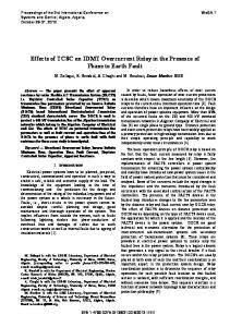
Fig. 1
DIAGRAMMA DI FUNZIONAMENTO
5
60
20
80
5
100
5
15
10
0.1
10
0.1
Fig. 2 INHIBITION [s]
CURRENT [%Ie] (AC/DC)
OPERATIONAL DIAGRAM
Fig. 3
DELAY [s]
DIAGRAMA DE FUNCIONAMIENTO
A2 R 18
15
Hysteresis 5-30%
16 I
Max Current 0.05-1 Ie
t Inhibition 0.1-10s
2
Delay 0.1-10s
Delay 0.1-10s
Manual Reset
30
FUNKTIONSDIAGRAMM
RELAY RESET
25
5
HYSTERESIS [%]
A1 A2
ON
20
10
I23 I GB E D 03 05
PREDISPOSIZIONE 1) (Fig. 1) Impostare la soglia d’intervento di massima corrente mediante il potenziometro “Current”. La scala e’espressa in % della corrente nominale (Ie) cioè del fondo scala scelto in morsettiera. Campo di regolazione 5÷100%. Esempio: tipo di relè: DLA1 10 fondo scala (Ie) : 5A (morsetti C-B2) soglia di massima desiderata : 3A potenziom. “Current” : 3/5*100 = 60% 2) (Fig. 2) Impostare i tempi d’inibizione e d’intervento rispettivamente mediante i potenziometri “Inhibition” e “Delay”. Campo di regolazione 0,1÷10s Nota: Il tempo d’inibizione all’accensione consente di ignorare le correnti di spunto quando il carico viene inserito, posto che il relè amperometrico e il carico vengano alimentati contemporaneamente (vedi esempio 1). Si tenga presente che durante il tempo d’inibizione, il tempo di ritardo all’intervento viene tenuto azzerato. 3) (Fig. 3) Impostare la soglia di isteresi al ripristino mediante il potenziometro “Hysteresis”. La scala è espressa in % della soglia “Current” impostata. Campo di regolazione 5÷30% . IMPORTANTE!! Prima di alimentare l’apparecchio ed inserire il carico a. verificare il collegamento dei morsetti; un errore puo’danneggiare gravemente l’apparecchio! b. in caso di inserzione diretta, controllare che la corrente presunta da rilevare non sia superiore al fondo scala (Ie) scelto e non ecceda in nessun caso i valori di sovraccaricabilità permanente riportati in tabella 1 c. in caso di inserzione mediante T.A., controllare che il rapporto di trasformazione del T.A. (/1/5A) coincida con il fondo scala (Ie) scelto e verificare che la sua corrente secondaria non superi in nessun caso i valori di sovraccaricabilità permanente riportati in tabella 1.
TABELLA 1 CARATTERISTICHE INGRESSI AMPEROMETRICI
SETTING UP 1) (Fig. 1) Set the maximum current threshold through the potentiometer “Current”. The % value is referred to the rated current (Ie) that is the selected end scale. Range 5-100%. Example: type: DLA1 10 end scale (Ie): 5A (terminals C-B2) max current threshold: 3A “Current” potentiometer: 3/5*100 = 60% 2) (Fig. 2) Set both trip time and inhibition time through the potentiometers “Inhibition” and “Delay” respectively. Range 0.1-10s. Notes: -The inhibition time avoids tripping at load inrush, assuming that the load and the unit are switched on contemporary (see example 1). The trip delay is enabled only after the inhibition time 3) (Fig. 3) Set the potentiometer “Hysteresis”. The % value is referred to the set-point “Current”. Range 5-30%. WARNING!! Before powering the unit and switching on the load: a. Check the connections: an error could seriously damage the unit! b. In case of direct connection, check that the current to be monitored is lower than selected rated value Ie (end scale) and check that it never exceeds the continuous overload capability (see table 1). c. In case of connection through C.T., check that the C.T. ratio (/1A or /5A) corresponds to the selected scale (Ie) and check that its secondary current never exceeds the continuous overload capability (see table 1).
TABLE 1 CURRENT INPUTS
PREDISPOSICIÓN 1) (Fig. 1) Ajustar el valor de sisparo de máxima corriente mediante el potenciómetro “Current”. La escala esta expresada en % de la corriente nominal (Ie) este es el fondo de escala escogido en la bornera. Rango 5-100% Ejemplo: tipo de relé: DLA1 10 Fondo escala (Ie): 5 A (bornes C-B2) Valor de disparo seleccionado: 3 A. Potenciómetro “Current”: 3/5*100= 60% 2) (Fig. 2) Ajustar el tiempo de inhibición y de disparo respectivamente mediante el potenciómetro “Inhibition” y “Delay”. Campo de regulación: 0,1-10 S. Nota: El tiempo de inhibición previene disparos por picos de corriente al momento de la conexión de las cargas, asumiendo que la carga y la alimentación auxiliar estan conectadas a la misma fuente de tensión (ver ejemplo 1). El tiempo de disparo esta disponible solamente después del tiempo de inhibición. 3) (Fig. 3) Ajustar el valor de histéresis al rearme mediante el potenciómetro “Hysteresis” La escala este expresada en % del valor “Current” ajustado. Rango: 5-30%. IMPORTANTE!! Antes de alimentar el aparato y conectar la carga. a. Verificar las conexiones; un error puede dañar seriamente el aparato. b. En caso de conexión directa, controlar que la corriente presunta es menos que el rango seleccionado a fondo de escala (Ie) y que no exceda el valor de sobrecarga permanente. (ver tabla 1). c. En caso de conexión mediante TC. Controlar que la relación de transformación (/1 A o /5 A) corresponda con la escala seleccionada, y comprobar que el valor secundario no supere el valor de sobrecarga permanente. (ver tabla 1).
TABLA 1 CARACTERÍSTICAS DE LAS ENTRADAS DE CORRIENTE
INBETRIEBNAHME 1) (Bild 1) Die Schaltschwelle für max. Strom durch Poti “Current” wählen. Der Wertebereich ist in % des Nennstroms (Ie) ausgedrückt, das heißt des an der Klemme gewählten Skalenendwerts. Einstellbereich: 5÷100%. Beispiel: relaistyp: DLA1 10 Skalenendwert Ie: 5A (Klemmen C-B2) Gewünschte Schaltschwelle: 3A Potent. “Current”: 3/5x100 = 60%. 2) (Bild 2) Einstellung der Anlaufüberbrückung und Ansprechzeiten durch Potis “Inhibition” bzw. “Delay”. Einstellbereich 0,1÷10s. Bemerkung: Dank der Anlaufüberbrückung werden bei der Lastzuschaltung Anlassspitzenströme vermieden, wenn der Stromwächter und die Last gleichzeitig versorgt werden (siehe Beispiel 1). Es ist zu beachten, dass die Verzögerungszeit während der Anlaufüberbrückung nicht aktiv ist. 3) (Bild 3) Einstellung durch Poti “Hysteresis” der Hystereseschwelle bei Reset. Der Wertebereich ist in % der eingestellten Schaltschwelle “Current” ausgedrückt. Einstellbereich 5÷30%. WICHTIG! Vor der Versorgung des Gerätes und der Lastzuschaltung: a. Anschluss der Klemmen überprüfen. Ein Fehler kann das Gerät schwer beschädigen. b. Bei direktem Anschluss ist sicherzustellen, dass der zu überwachende Strom unter dem gewählten Skalenendwert Ie liegt und keinesfalls die in der Tabelle 1 angegebenen Werte der Dauerüberlastbarkeit überschreitet. c. Bei Anschluss durch Stromwandler ist sicherzustellen, dass das Umwandlungsverhältnis des Stromwandlers (/1/5A) mit dem gewählten Skalenendwert Ie übereinstimmt und dass der Sekundärstrom keinesfalls die in der Tabelle 1 angegebenen Werte der Dauerüberlastbarkeit überschreitet. TABELLE 1 EIGENSCHAFTEN DER STROMEINGÄNGE
Tipo Type Tipo Typ
Fondo Scala [Ie] End scale [Ie] Fondo escala (Ie) Endskala-Wert (Ie)
Sovraccaricabilità permanente Continuous overload capability Capacidad de sobrecarga permanente Dauerüberlastbarkeit
Impedenza d’ingresso Input impedance Impedancia de entrada Eingangswiderstand
Campo di misura Measuring range Rango de Medición Messbereich
DLA1 10
1A 5A 10A
2A 10A 15A
0.1 ohm 0.02 ohm 0.01 ohm
0.05-1A 0.25-5A 0.5-10A
CODICE DI ORDINAZIONE Codici di ordinazione Order code Código de pedido Bestellcode A1
ORDER CODE
CODIGO DE PEDIDO
BESTELLCODE
31 DLA1 10 24
31 DLA1 10 48
31 DLA1 10 110
31 DLA1 10 220
A1-A2 = 24VAC
A1-A2 = 48VAC
A1-A2 = 110-127VAC
A1-A2 = 220-240VAC
A2
3
Esempio 1 : Schema di collegamento con inibizione del controllo amperometrico in fase di avviamento del motore
Example 1 : Wiring diagram for current monitoring inhibition at motor starting
Ejemplo 1: Esquema de conexión para control de corriente, inhibición al arranque del motor
L1 L2 L3
Beispiel 1: Anschlussplan mit Unterdrückung der Stromüberwachung in der Anlaufphase des Motors
Uaux
K1
I23 I GB E D 03 05
K1
A1 A2
C B.
DLA1
DIMENSIONI (mm) IDENTIFICAZIONE TERMINALI
DIMENSIONS (mm) TERMINALS IDENTIFICATION
DIMENSIONES (mm) IDENTIFICACIÓN DE TERMINALES
MASSE (mm) IDENTIFIZIERUNG DER KLEMMEN
99.5
78.8
A1 15 B1 B2 B3 C
DLA1 R Y1 Y2 16 18 A2
45
4
I
I23 I GB E D 03 05
DATI TECNICI CIRCUITO DI ALIMENTAZIONE
Tipo
Ue
Range
Massima tensione di commutazione
Tensione nominale (Ue) e limiti di funzionamento
31 DLA1 10 24
24VAC
(20÷27VAC)
Corrente nominale termica (Ith)
8A
31 DLA1 10 48
48VAC
(40÷53VAC)
B300
31 DLA1 10 110
110÷127VAC
(93÷140VAC)
Designazione secondo IEC/EN 60947-5-1
31 DLA1 10 220
220÷240VAC
(187÷264VAC)
Vita meccanica
30x106 cicli
50/60Hz ±5%
Vita elettrica (con carico nominale)
105 cicli
Potenza massima assorbita
1,8VA
ISOLAMENTO
Immunità alle microinterruzioni
30ms
Tensione nominale d’isolamento
500V
Prova impulsiva (1,2/50µs)
5kV
Frequenza nominale
INGRESSO AMPEROMETRICO Corrente nominale Ie (fondo scala)
31 DLA1 10 .. 1/5/10A (selez.)
Limite termico di breve durata
1A 24A per 1s 8 Ie per 3s 6 Ie per 5s 2,5 Ie per 20s 2A permanente
Altre caratteristiche
5A 100A per 1s 8 Ie per 3s 6 Ie per 5s 2,5 Ie per 20s 10A permanente
400VAC
Prova di tenuta a frequenza di esercizio 2,5kV (50Hz,60s) 10A 100A per 1s 8 Ie per 3s 6 Ie per 5s 2,5 Ie per 20s 15A permanente
SEGNALAZIONI
LED verde “ON” : presenza alimentazione LED rosso “Relay”: intervento per massima corrente
CONDIZIONI AMBIENTALI Temperatura d’impiego
-10...+60°C
Temperatura di stoccaggio
-30...+80°C
GRADO DI PROTEZIONE
vedere tabella 1
SOGLIE DI INTERVENTO/RIPRISTINO
Contenitore
IP40
Set-point “Current”
0,05÷1 Ie (regolabile)
Morsetti
IP20
Errore di ripetibilita’