Original Article Removing Distortion of Periapical Radiographs in Dental Digital Radiography Using Embedded Markers in an External frame Rahele Kafieh, Mahdi Shahamoradi1, Ehsan Hekmatian1, Mehrdad Foroohandeh1, Mostafa Emamidoost1 Departments of Biomedical Engineering, Medical Image and Signal Processing Research Center, 1Oral Radiology, Faculty of Dentistry, Isfahan University of Medical Sciences, Isfahan, Iran Submission: 19-09-2012
Accepted: 06-10-2012
Abstract To carry out in vivo and in vitro comparative pilot study to evaluate the preciseness of a newly proposed digital dental radiography setup. This setup was based on markers placed on an external frame to eliminate the measurement errors due to incorrect geometry in relative positioning of cone, teeth and the sensor. Five patients with previous panoramic images were selected to undergo the proposed periapical digital imaging for in vivo phase. For in vitro phase, 40 extracted teeth were replanted in dry mandibular sockets and periapical digital images were prepared. The standard reference for real scales of the teeth were obtained through extracted teeth measurements for in vitro application and were calculated through panoramic imaging for in vivo phases. The proposed image processing thechnique was applied on periapical digital images to distinguish the incorrect geometry. The recognized error was inversely applied on the image and the modified images were compared to the correct values. The measurement findings after the distortion removal were compared to our gold standards (results of panoramic imaging or measurements from extracted teeth) and showed the accuracy of 96.45% through in vivo examinations and 96.0% through in vitro tests. The proposed distortion removal method is perfectly able to identify the possible inaccurate geometry during image acquisition and is capable of applying the inverse transform to the distorted radiograph to obtain the correctly modified image. This can be really helpful in applications like root canal therapy, implant surgical procedures and digital subtraction radiography, which are essentially dependent on precise measurements.
Key words: Dental, image analysis, periapical, radiography
Introduction Nowadays, digital dental image analysis is widely employed in diagnosis, treatment planning, and prognosis by dentists.[1‑5] Digital imaging can be utilized in endodontic applications, evaluations after and before implant surgery, and dental processes needing multiple imaging. However, the distortions caused by incorrect angulations of radiographic cone toward the teeth and the sensor must be solved by additional image processing methods; otherwise, such a distortion may cause inevitable errors, likely to affect the measurements which are very important in procedures like root canal therapy, implant surgery and subtraction radiography. To eliminate this misrepresentation, we proposed a noninvasive method in radiographic imaging. This method
introduces a new arrangement in geometry of radiographic imaging in order to provide a condition to measure the changes appeared due to incorrect placement of cone toward the teeth and the sensor. Consequently, this method can remove these unwanted changes from the affected image by applying an inverse transform.
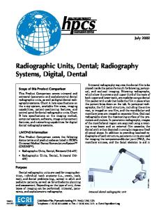
Materials and Methods In the first phase of the study, the in vitro phase, quantitative measurements were calculated on 40 extracted teeth which were then replanted in dry mandibular sockets to undergo periapical imaging [Figure 1]. In the second phase, the in vivo phase, digital panoramic radiographs of 5 volunteers, in Dental School of Isfahan University of medical sciences were used as standard references and the patients kindly accepted and signed consent forms which let us taking an extra periapical image in our proposed setup.
Address for correspondence: Mrs. Rahele Kafieh, Department of Biomedical Engineering, Medical Image and Signal Processing Research Center, Isfahan University of Medical Sciences, Isfahan, Iran. E‑mail:
[email protected]
Vol 2 | Issue 4 | Oct-Dec 2012
219 Journal of Medical Signals & Sensors
Kafieh, et al.: Dental distortion removal
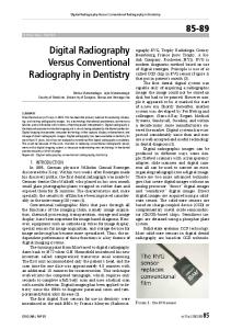
The measurements on real teeth were performed by a caliper. The widest part of the tooth was measured for horizontal measurement and the distance from end to end was evaluated to represent the vertical length. Knowing the resolution of imaging device, the measured values were calculated in pixels and were used as gold standards in error estimation. For the second phase of study, measurements on digital panoramic images were simply done by getting the cursor’s location through mouse clicks of the expert. In order to remove the image distortions, a new method based on embedded landmarks aligned by an external frame was applied. For this purpose, we designed a radiolucent frame covered with a rectangular network. The proposed width for comprising lines is 0.2 mm and the side length for parallelograms is suggested to be 2 mm. [Figure 2a] The most important shortness of our previous method[6] was the superimposition of the embedded square mesh with the region of interest (periapical zone), which could cause misdiagnosis [Figure 2b]. To solve this problem, a special frame with an empty area in lower part of the frame was designed to be used instead of a full cover of squares [Figure 2a]. Furthermore, we used smaller mesh compared with our first experiment to improve the accuracy of the method. The frame was mounted on the top of the radiographic cone without any intrusion on the patient [Figure 3]. The proposed imaging technique for periapical radiography is a combination of parallel and bisecting periapical image acquisition methods.[7] To clear up, the angle between tooth and sensor is similar to bisecting method, however, the angle between the cone and the tooth is like parallel imaging. In standard geometry (parallel frame with the sensor, and both parallel with the teeth), the squares on the frame would appear with a same size in the acquired image. However, if the parallelization is not provided, the squares would be distorted and skewed and would appear in a shape of rectangles or trapezoids. At this stage, by calculating the imposed distortion on squares, the overall image distortion can be estimated and corrected. In this method, after applying noise removal in preprocessing step, the proposed image processing algorithms are applied to find specific points (Landmarks) on each image[8] [Figure 4].
Figure 1: Extracted tooth replanted in a dry mandibular socket
a
b
Figure 2: (a) Intersecting vertical and horizontal radio‑opaque lines (square mesh) on the frame with smaller squares on the upper part of the frame. (b) Old frame with bigger squares on the whole area
Figure 3: The frame installed on the top of the radiographic cone
be used in this step). The basic formulas of a projective The locations of the detected points (depicted by green transform are like[9]: markers in Figure 5) were compared to corresponding positions in the case of standard geometry (depicted by [up v p w p ] = [ x y w] × Tinv red markers in Figure 5). The respective coordinates are then utilized to correct the distortion (magnification, Where: translation and rotation) by a projective transform, up vp which needs at least four points for estimation of the = u = v wp wp transform (four corners of one square are proposed to 220 Journal of Medical Signals & Sensors
Vol 2 | Issue 4 | Oct-Dec 2012
Kafieh, et al.: Dental distortion removal
Assuming: A D G Tinv = B E H C F I u=
Ax + By + C Gx + Hy + I
v=
Dx + Ey + F Gx + Hy + I
An example of the corrected image is demonstrated in Figure 6, where the incorrect magnification, translation and rotation are all removed and the squares are in the accurate size of squares in standard geometry. Therefore, we can expect the dental structures to have the right size, similar to what was expected in an ideal case of imaging (parallel frame with the sensor, both parallel with the teeth).
Figure 4: Some image processing algorithms applied in order to find specific points
Results The results of this research are categorized in two groups. In order to evaluate the results of the first group, the extracted teeth were replanted in dry mandibular sockets and the images were taken in vitro. The most important advantage of in vitro phase is that the real length and width of each tooth could be measured manually and exactly, therefore the calculation of errors could be more reliable. However, it is crucial to establish a real condition to examine the actual performance of the method. Therefore, the accuracy of the proposed method was checked in the second phase of the research that took place through in vivo radiographic examinations. For this purpose, the real length and width of each tooth cannot be measured manually (since the teeth is not extracted) and digital panoramic images of the same person can be used for the calculations. Table 1 shows the examined teeth in this step (20 incisors, 10 premolars and 10 canins).
Figure 5: A sample in vitro image. Green points indicate the detected points and the red Points are the ones which should be found in the case of standard geometry
In the first phase, quantitative results were calculated on 40 extracted tooth collected and replanted in dry mandibular sockets and the areas were imaged in 7 situations, one standard geometry, 3 incorrect geometries with 10, 20 and 30 degrees between sensor and the teeth [Figure 7a] and 3 incorrect geometries with 10, 20 and 30 radial degrees [Figure 7b] between sensor and parallel plane to the tooth. To calculate the efficiency of the method, we have: XX[mean horizontal error] =
of images ∑ inum X i − X ri =1
num of images
Vol 2 | Issue 4 | Oct-Dec 2012
Figure 6: The modified image
YY [mean vertical error] =
of images ∑ inum Yi − Yri =1
num of images 221 Journal of Medical Signals & Sensors
Kafieh, et al.: Dental distortion removal
Err [mean rational Error] =
X i − X ri Y − Yri ) + i X ri Yri 2 × num of images
of images ∑ inum ( =1
YY 2 [mean vertical error] =
of images ∑ inum Yi − Yri =1
num of images
TA[Total Accuracy] = {1 − Err} × 100 Where Yi is the length of each tooth and Xi is the related width [Figure 8], both calculated after imposing the proposed transform. Xri and Yri are real magnitudes which can be measured from the extracted teeth. TA (Total accuracy) in an ideal method should be equal to 100% (no difference between measured and calculated lengths). XX indicates the mean value of horizontal error in millimeters and similarly YY indicates the mean value of vertical error in millimeters. In order to have a better visualization of the performance, Err (mean rational error) is calculated to show the mean value of expected error in measurement of each millimeter. For example, Err = 0.02 means that the expected outcome in measuring one millimeter is between 0.98 to 1.02 mm. Table 2 and Figure 9 show the mentioned values for our proposed method. It also should be noted that the errors in standard geometry may be expected not to be zero due to magnification which is shown in Figure 7A. However, since we know the exact size of the squares on the frame, we finally rescale the whole image to give the correct size to the squares and consequently to remove the magnification error. In the second phase, Yri are magnitudes calculated from digital panoramic radiographs of 5 volunteers, who underwent the panoramic imaging in Dental School of Isfahan University of medical sciences and kindly accepted to be taken an extra periapical image in our proposed setup [Figure 10]. Since the horizontal measurements of panoramic imaging are not as accurate as vertical assessments, we just consider the vertical errors in our calculations. Table 1 shows the corresponding results for the proposed method.
a
b
c Figure 7: (a) Standard geometry; (b) Incorrect geometries with θ degrees between sensor and the teeth; (c) Incorrect geometries with θ radial degrees between sensor and the teeth
Figure 8: X and Y measurements
Table 1: Errors and accuracy of the proposed method through in vivo phase Incisor Incisor Canin Canin Premolar Premolar Total (up) (down) (up) (down) (up) (down) mean YY2 (mm) 0.311 Err2 0.03 TA2 97
0.341 0.032 96.8
0.482 0.042 95.8
0.458 0.041 95.9
0.347 0.033 96.7
0.348 0.035 96.5
0.381 0.035 96.4
Table 2: Errors and accuracy of the proposed method through in vitro phase XX (mm) YY (mm) Err TA%
θ=10
θ=20
θ=30
Total mean
0.343 0.64 0.035 96.5
0.39 0.773 0.041 95.9
0.46 0.871 0.043 95.7
0.39 0.76 0.039 96.0
222 Journal of Medical Signals & Sensors
Figure 9: Err (mean rational error) for our proposed method with different degrees of distortion
Vol 2 | Issue 4 | Oct-Dec 2012
Kafieh, et al.: Dental distortion removal
images. In order to achieve reliable results, the panoramic imaging parameters were set to 100% scale which is introduced to transform the images to have their real lengths. Another interesting point in this study is that the results of in vitro phase show lower accuracy than in vivo cases. This may be a result of applying very high distortions (30 degrees) during in vitro imaging, a value which is really rare to happen during in vivo imaging.
a
b Figure 10: Sample panoramic image and two periapical images
Err 2[mean ration Error] =
Yi − Yri ) Yri num of images
of images ( ∑ inum =1
TA2[Total Accuracy] = {1 − Err} × 100
Discussion The proposed distortion removal method is perfectly able to identify the possible inaccurate geometry during image acquisition and is capable of applying the inverse transform to the radiograph to obtain the modified image. This can be really helpful in applications like root canal therapy, implant surgical procedures and digital subtraction radiography, which are essentially dependent on precise measurements. However, it should be noted that the automatic discrimination of corner points of the rectangle in images with low quality (like Figure 10b) is cumbersome and in some cases it fails. To overcome this shortcoming, a user interface is designed to get the corner points interactively or accept any change to the results of the automatic corner detection by the expert. This semiautomatic method can even improve the results and simultaneously make the method applicable to images with very low quality. Furthermore, we should mention that the best standard for comparison of in vivo results is cone beam CT. However, the patients referred to experience cone beam CT imaging technique are usually suffering from severe illnesses and we could not find any volunteer to undergo our proposed setup of periapical imaging. Therefore, we had no choice except comparing our result with panoramic
Vol 2 | Issue 4 | Oct-Dec 2012
In conclusion, the proposed method can provide better digital dental radiographic images through removing foreshortening and elongation errors and can be used for the more accurate interpretation of dental radiographic images. Furthermore, by applying the differential methods, it makes treatment procedure more accurate and provides successful patient follow‑up.
References 1. Mol A, van der Stelt PF. Application of digital image analysis in dental radiography for the description of periapical bone lesions: a preliminary study. IEEE Trans Biomed Eng 1991;38:357-59. 2. Goebel P, Belbachir A, Truppe M. Background removal in dental panoramic x-ray images by the a-trous multiresolution transform. Proceedings of the European Conference on Circuit Theory and Design; vol. 1. 2005. p. 331-4.. 3. Yasuda Y, Yashiro K, Takada K. Digital mapping of the interocclusal distance during biting by image processing of occlusal registration. IEEE EMBS Asian-Pacific Conference on Biomedical Engineering; 2003. p. 272-3. 4. Leung C, Yiu K, Zee K, Tsui W. Image registration in intra-oral radiography. Engineering in Medicine and Biology Society, 2005, 27th Annual International Conference of the Engineering in Medicine and Biology Society, 2006. p. 3206-9. 5. Lu X. Design and implementation of cooperative distributed dental medical information system. Proceedings of the Ninth International Conference on Computer Supported Cooperative Work in Design; 2005. p. 799-803. 6. Kafieh R, Shahamoradi M, Lotfi Mahyari T, Hekmatian E, Foroohandeh M, Emamidoost M. A method for removing distortion of periapical images in dental digital radiography. 3rd Congress of Oral and Maxilofacial Radiology; 2011; Tehran, Iran; 2011. p. 132-36. 7. Bean L. Comparison of bisecting angle and paralleling methods of intraoral radiology. J Dent Edu 1969;441:33-45. 8. Jain AK. Fundamentals of digital image processing: Prentice hall: Englewood Cliffs, NJ; 1989. 9. Zisserman A. Notes on geometric invariance in vision. Tutorial, British Machine Vision Conference; 1992. How to cite this article: Kafieh R, Shahamoradi M, Hekmatian E, Foroohandeh M, Emamidoost M. Removing distortion of periapical radiographs in dental digital radiography using embedded markers in an external frame. J Med Sign Sens 2012;2:219-24. Source of Support: Nil, Conflict of Interest: None declared
223 Journal of Medical Signals & Sensors
Kafieh, et al.: Dental distortion removal
BiographIES Rahele Kafieh received the BS degree from Sahand University of Technology, Iran, in 2005 and the MS degree from the Isfahan University of Medical Sciences, Iran, in 2008, both in biomedical engineering. She is currently working toward the PhD degree in the Department of Biomedical Engineering at Isfahan University of Medical Sciences. Her research interests are in biomedical image processing, computer vision, graph algorithms, and sparse transforms. She is a student member of the IEEE and the IEEE Signal Processing Society. E-mail:
[email protected] Mahdi Shahmoradi received his DDS degree from Faculty of Dentistry, Isfahan University of Medical Sciences, Iran, in 2007. He is currently working toward the PhD degree in the Department of Dental Biomaterials, University of Sydney. His research interests are in biomimetics, biomaterials characterization and nanomechanics.
Ehsan Hekmatian is assistant professor of dentomaxillofacial radiology of Isfahan detistry school. His field is quality assurance radiology. E-mail:
[email protected] Mehrdad Foroohandeh is a dental student since 2007 at dental Department, Isfahan University of Medical Sciences. His research interests are in dental image process and oral cancer. E-mail:
[email protected] Mostafa Emamidoost is a dental student since 2007 at dental Department, Isfahan University of Medical Sciences. His research interests are in dental image process and oral cancer. E-mail:
[email protected]
E-mail:
[email protected]
224 Journal of Medical Signals & Sensors
Vol 2 | Issue 4 | Oct-Dec 2012