X International Conference on Antenna Theory and Techniques, 2015, Kharkiv, Ukraine
RECENT ADVANCES IN MILLIMETER-WAVE RADARS D. M. Vavriv, O. O. Bezvesilniy, V. A. Volkov, A. A. Kravtsov, and E. V. Bulakh Institute of Radio Astronomy of the National Academy of Sciences of Ukraine, Kharkov, Ukraine E-mail:
[email protected]
Abstract The usage of millimeter-wave radar systems is widened to a number of civil applications including: airborne radars for obstacle avoidance, altimetry and landing aids, automotive radars for collision avoidance, driving safety support, autonomous vehicle control, meteorological radars, radars for remote sensing applications, and radars for medical imaging and diagnostic. We review some of these developments supported by advances in millimeter-wave components and achievements in signal processing technique. A recently developed at the Institute of Radio Astronomy ground based millimeter-wave synthetic aperture radar (SAR) is described in more details as an example of the activity in the field. The hardware and software solutions introduced into the radar are described along with the results of the first radar tests. Keywords: Millimeter-wave radar, airborne radar, meteorological radar, signal processing, motion error compensation, radar applications, radar imaging, synthetic aperture radar.
1. INTRODUCTION Recent advances in the technology of millimeter-wave components have induced rapid development of reliable millimeter-wave radars for a variety of applications. In turn, the commercialization of some radar systems for wide civilian applications has triggered the development of rather sophisticated radar units (see, e. g., Fig. 1). Millimeter-wave radars are used as airborne radars for obstacle avoidance, altimetry and landing aids, and as automotive radars for collision avoidance, driving safety support, and autonomous vehicle control. Millimeter-wave radars are also widely used in remote sensing application, in particular as meteorological radars, airborne and spaceborne synthetic aperture radars (SAR), radars for medical imaging and diagnostic, and so on. The success of millimeter-wave radars comes from several important benefits of millimeter waves compared to microwaves. Millimeter-wave radars are more compact in size and lighter in weight. In particular, the antenna size and weight can be reduced significantly at millimeter waves while providing the same antenna beam width and antenna gain. The radar pulse frequency bandwidth can be very high (up to 1 GHz and higher) while being small compare to the carrier frequency. It means that it is much easier to achieve high range resolution at millimeter waves. The radar cross section (RCS) of terrain, natural objects and man-made targets demonstrates significant differences at millimeter waves as compared to
978-1-4799-8557-9/15/$31.00©2015 IEEE
longer microwaves that provides valuable information about the scene. Millimeter-wave radars are shown to be very useful in meteorological applications [1, 2] for observation of small water droplets and ice crystals (hydrometeors) in clouds and precipitations. Millimeter-wave meteorological radars typically operate at 35 GHz or 94 GHz carrier frequency. However, the exploitation of the higher frequencies of 140 GHz and 215 GHz that also correspond to the atmospheric windows of low attenuation are now considered as promising for dual-wavelengths 35-GHz/140-GHz or 35-GHz/215GHz measurements [3]. Ka-band and W-band millimeter-wave meteorological radars have been developed and produced at the Institute of Radio Astronomy of the NAS of Ukraine [4-10] (see Fig. 2). These systems form a significant export potential of the Institute. Dozens of such meteorological radars are operated in many countries around the world. Millimeter-wave synthetic aperture radars [11-14] also take advantages of compact size, light weight, high sensitivity and high range resolution. Additionally, the same cross-range resolution can be achieved with a shorter synthetic aperture at millimeter wavelengths. It is important for airborne SAR systems installed on light-weight aircrafts and UAVs operating at low altitudes (up to 2 km) since the shorter synthetic aperture makes the system more robust to the trajectory and orientation instabilities of the SAR platform. The shorter aperture is also especially important for ground-based SAR systems (GB-SAR), for which the length of the synthetic aperture is limited.
D. M. Vavriv, O. O. Bezvesilniy, V. A. Volkov, A. A. Kravtsov, and E. V. Bulakh
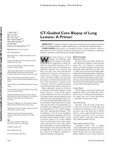
Fig. 1. The single-chip radar transceiver for an automotive radar (77 GHz) developed by the University of Melbourne [26].
toring in sea ports, for surveillance of runways in airports etc. [15-19]. Advanced radar techniques such as polarimetry and interferometry are also available and applied at millimeter waves. Polarimetric observations are widely used in radar meteorology [1, 2] to retrieve the shape and type of hydrometeors and to enhance the accuracy of quantitative measurements of precipitation rate and cloud water or ice content. Interferometric measurements are extensively used in synthetic aperture radars [20] for 3-D imaging and change detection. During the last two decades, the synthetic aperture radar technique has also been intensively advanced at the Institute of Radio Astronomy. In particular, this activity has resulted in the development of the Kuband and X-band airborne SAR systems [21-25]. In this paper, an experimental ground-based SAR system operating at Ka-band recently developed at the Institute is described. The system is designed to be operated from a top of a hill or from a roof of a building etc. for imaging of the underlying ground terrain. The radar hardware system, operating mode and original data processing techniques are described in the paper. Benefits of a high-duty-cycle long-LFM-pulse mode (quasi-continuous mode) over the common frequencymodulated continuous wave (FMCW) mode are discussed. An effective adaptive matched filtering for range compression has been introduced that provides high dynamic range and high coherency for the radar system. The achieved performance of the GB-SAR system is illustrated with experimental data.
2. GROUND-BASED SAR PRINCIPLES A ground-based synthetic aperture radar (GB-SAR) system operating at Ka-band has been developed and tested. The system is designed to be placed on a top of a hill or on a roof of a building for imaging of the underlying ground terrain. The GB-SAR antenna has a wide beam of 40° in the horizontal plane (in the azimuth) and a 10° beam in the vertical plane (in the elevation). Such beam illuminates a wide sector of the scene as shown in Fig. 3.
Fig. 2. Ka-band polarimetric Doppler meteorological scanning radar [10]. Airborne SAR system find their applications in monitoring of the environment, for mapping, for disaster area inspection and so on, operating day and night under various weather conditions, despite clouds, smoke and dust. The GB-SAR systems can be used for monitoring changes, for example, for observation of open-air mining sites, for ships safety moni-
Fig. 3. GB-SAR operating geometry. High range resolution is achieved by the compression of long pulses with linear frequency modulation (LFM). The range resolution is given by
ρ R = K R c /(2BLFM ) ,
X International Conference on Antenna Theory and Techniques, 2015, Kharkiv, Ukraine
(1)
Recent Advances in Millimeter-Wave Radars where BLFM is the LFM-pulse frequency bandwidth, K R is the broadening coefficient that comes from the weighting window applied to control the compression side lobes, c is the speed of light. High azimuth resolution is achieved due to the synthetic aperture technique. The radar is placed on a moving platform (a trolley on rails) that is translated in the direction perpendicular to the radar beam. The backscattered radar pulses are collected along the path and combined coherently to form the synthetic aperture. The platform path length is the length of the synthetic aperture. The aperture length is commonly limited to a few meters, thus limiting the azimuth resolution. It should be noted that the aperture length is constant for all ranges. As the result, the azimuth resolution of the GB-SAR system is range-dependent. The azimuth resolution is actually the angular resolution and it is determined as
θX =
ρX R
= KX
λ 2LS
,
(2)
where ρ X is the cross-range resolution in meters at range R , K X is the broadening coefficient of the weighting window applied in the azimuth direction, λ is the radar wavelength, and LS is the aperture length.
3. RADAR HARDWARE Main characteristics of the GB-SAR system are listed in Table 1. The block-scheme of the system is shown in Fig. 4. The transmitter is built by using a solid-state output amplifier and a direct digital frequency synthesizer (DDS) to produce the output signal waveform. There are two heterodynes in the radar. The 1st heterodyne is based on a dielectric resonator and generates the signal at the frequency of 8.5 GHz. The 2nd heterodyne uses a voltage-controlled oscillator (VCO) and generates the signal at the frequency of 1380 MHz. The signal with the linear frequency modulation (LFM) at the carrier frequency of 280 MHz is formed with the DDS. The synchronization is performed with a 100-MHz reference signal from a crystal oscillator. The signals from the DDS and the 2nd heterodyne come to a quadrature modulator that is used to form the LFM-signal at the carrier frequency of 1100 MHz. The obtained signal and the signal from the 1st heterodyne (multiplied by 4) come to a mixer and a power amplifier that finally forms the transmitter signal at the frequency of 35.1 GHz. The power of the transmitter signal that goes to the transmitting antenna is about 1 Watt. A small part of the transmitter signal (about –50 dB) is split here to the 2nd channel of the receiver. It is required for an adaptive pulse compression technique discussed later. The receiver has two identical channels. The 1st one is used to sample the backscattered pulses, and the 2nd one is required to sample the transmitted pulses. The received signals are amplified, filtered and transformed consequently to the 1st intermediate fre-
quency of 1100 MHz and then to the 2nd intermediate frequency of 280 MHz. The obtained signals are sampled with two 16-bits ADCs at the frequency of 160 MHz and, finally, come to a digital signal processing system for further processing, including the digital quadrature demodulation, range compression, etc. Table 1. Characteristics of the GB-SAR system. Radar frequency 35 GHz Transmitted power < 1 Watt Pulse repetition frequency 2.5 kHz Pulse duration 250 µs Duty cycle 62.5% 3-dB antenna beam width in hori40°/10° zontal / vertical plane LFM pulse bandwidth 48 MHz Range resolution 4m Length of the synthetic aperture ~1m Trolley motion time and speed ~ 5 s and 20 cm/s Synthetic beam width (angular 0.32° resolution) Azimuth (cross-range) resolution ~ 1 m at (it grows linearly with range) range 200m The system is equipped with two separate horn antennas for simultaneous transmission of the long LFM pulses and reception of the radar returns. The system has been set up on a trolley on rails. The received radar data was recorded on a hard disk drive on a common PC that also has been placed on the trolley.
4. ADAPTIVE RANGE COMPRESSION The GB-SAR system usually operates at ranges from tens of meters to a few kilometers. It means that the radar should transmit and receive signals simultaneously. In such mode, the receiver faces a problem of a strong input signal that is a sum of the transmitter signal leakage within the radar hardware and strong signals reflected from very close targets surrounding the radar. This undesired strong input signal limits the radar ability to detect useful weak signals from distant targets. It means that the receiver with a very high dynamic range is required. The usage of the separate antennas for transmission and reception allows to reduce the transmitter signal leakage to the level better than about –50 dB. However, this solution does not solve the problem of strong signal from nearby targets. The side lobes from close targets could be higher than the useful signal from distant targets. Thus, additional efforts are required to obtain very low pulse compression side lobes. In order to solve the above described problems, an effective adaptive matched filtering for range compression has been introduced to provide high dynamic range and high coherency for the radar system. A twochannel receiver has been used to record both the transmitted pulse and the backscattered pulse.
X International Conference on Antenna Theory and Techniques, 2015, Kharkiv, Ukraine
3
D. M. Vavriv, O. O. Bezvesilniy, V. A. Volkov, A. A. Kravtsov, and E. V. Bulakh
Fig. 4. Block-scheme of the GB-SAR system. The matched filter is adjusted to each transmitted pulse, compensating possible imperfections of transmitted LFM waveforms to obtain good pulse compression side lobes. Also, such approach improves the pulse-to-pulse radar coherency as a bonus. Apparently, this approach reduces the requirements to the radar hardware system, in particular, to the accuracy of the generated LFM waveforms. The adaptive range compression is performed as sRC ( n, τ ) =
1 2π
Bp / 2
∫ S Rx (n, f ) PA (n, f )e *
2πifτ
frequency-modulation continuous-wave (FMCW) mode. The achieved side lobe level is about –80 dB.
5.
EXPERIMENTAL RESULTS
In our experiments, the system was operated indoor overviewing the nearby terrain through the open window on the 4th floor of our Institute building. The Google Map image of the scene is shown in Fig. 5.
df . (3)
− Bp / 2
Here n is the pulse number, τ = 2R / c is the fast time, S Rx (n, f ) is the Fourier spectrum of the received signal, PA (n, f ) is the adaptive matched filter,
PA (n, f ) =
* PRx ref ( f )
PTx* (n, f )
Pref ( f ) ,
(4)
PTx ( n, f ) is the Fourier spectrum of the transmitted pulse, PRx ref ( f ) is the spectrum of the single refer-
ence backscattered radar pulse (without any amplitude or phase distortions), Pref ( f ) is the spectrum of the common reference LFM compression filter, p ref (τ ) = wref (τ ) exp[ iπγ LFM (τ − τ p / 2) 2 ] ,
(5)
wref (τ ) is the weighting window, γ LFM is the LFM rate, τ p is the pulse duration, Bp = γ LFMτ p is the
Fig. 5. Google Map image of the scene.
LFM-pulse frequency bandwidth. The adaptive matched filter approach poses the following restriction on the radar pulse operation mode. Two consequent transmitted pulses should not overlap in the backscattered signal. Therefore, a long-LFMpulse mode with a high duty cycle (a kind of quasicontinuous mode) was implemented instead of the
The scene is about 535 m to 535 m. The GB-SAR image is shown in Fig. 6. The combination of the two images is shown in Fig. 7 so that the GB-SAR echoes can be matched to the elements of the scene. For example, in the center of the image one can recognize the radar return from the aircraft Let L-410 Turbolet.
X International Conference on Antenna Theory and Techniques, 2015, Kharkiv, Ukraine
Recent Advances in Millimeter-Wave Radars
still mainly area of intensive studies and developments from the point of view of potential commercial radar applications.
ACKNOWLEDGMENT The authors would like to thank V. Vinogradov, O. Nechaev, V. Vasiliev, R. Kozhyn, Ie. Gorovyi, S. Sekretarov, A. Somov, and S. Sosnytskiy for their valuable contributions to this work and for fruitful discussions.
REFERENCES 1.
Fig. 6. GB-SAR image of the scene.
Fig. 7. Combined GB-SAR + Google Map image.
5. CONCLUSION The appearance on the market of a variety of millimeter-wave radar systems is because of both high demand for such systems and recent advances in the technology of the corresponding radar components. Besides, all principal radar techniques including Doppler processing, aperture synthesis, phase arraying, interferometry, and polarimetry have been successfully adopted for this wavelength band. The recent achievements in the digital technology and the signal processing technique have also essentially contributed to this field. It should be, however, noted that the above progress is mainly due to the advent of the systems operating at the frequencies around 35 GHz and 77 GHz. Essential part of the millimeter-wave spectrum, starting from about 95 GHz and higher, is
Mead J. B, Pazmany A. L., Sekelsky S. M., McIntosh R. E. 1994. “Millimeter-wave radars for remotely sensing clouds and precipitation”, Proceedings of the IEEE, 82, 12, 1891–1906. 2. Sauvageot H. 1992, ‘Radar Meteorology’. Boston; London: Artech House. 3. Battaglia A., Westbrook C. D., Kneifel S., Kollias P., Humpage N., Löhnert U., Tyynelä J., and Petty G. W. 2014. “G-band atmospheric radars: new frontiers in cloud physics”, Atmos. Meas. Tech., 7, 1527–1546. 4. Vavriv D. M., Volkov V. A., Bormotov V. N., Vinogradov V. V., Kozhin R. V., Trush B. V., Belikov A., and Semenuta V. Ye. 2002. “Millimeter-wave radars for environmental studies”, Radio Physics and Radio Astronomy, 7, 2, 121138. 5. Vavriv D. M., Volkov V. A., Vinogradov V. V., Kozhin R. V., and Schuenemann K. 2002. “95 GHz Doppler polarimetric cloud radar based on a magnetron transmitter”, Proc. of 32nd Microwave European Conference, September 23-27 (Milano, Italy). 6. Bezvesilniy O. O., Vavriv D. M. 2007. “Retrieving the median droplet diameter from Ka- and W-band dual-wavelength Doppler radar measurements”, International Journal of Remote Sensing, 28, 16, 3707–3712. 7. Vavriv D. M., Volkov V. A., and Bezvesilniy O. O. 2008. “Millimeter-Wavelength Meteorological radars”, Proc. of the German Microwave Conference, 392-396. 8. Volkov V. A. 2010. “Magnetron Based Radar Systems for Millimeter Wavelength Band – Modern Approaches and Prospects”, In: Microwave and Millimeter Wave Technologies: Modern UWB antennas and equipment, Ed.: I. Minkin, InTech, 459-488. 9. Sosnytskiy S. V. 2012. “Dealiasing Doppler Spectra in Meteorological Radars”, Radiofizika i Radioastronomia, 17, 1, 89-94. 10. Department of Microwave Electronics of the Institute of Radio Astronomy of the National Academy of Sciences of Ukraine http://radar.kharkov.com 11. Essen H., Brautigam M., Sommer R., Wahlen A., Johannes W., Wilcke J., Schlechtweg M., Tessmann A. 2009. “SUMATRA, a W-band SAR for
X International Conference on Antenna Theory and Techniques, 2015, Kharkiv, Ukraine
5
D. M. Vavriv, O. O. Bezvesilniy, V. A. Volkov, A. A. Kravtsov, and E. V. Bulakh
12.
13.
14.
15.
16.
17.
18.
19.
20.
21.
22.
UAV application”, International Radar Conference - Surveillance for a Safer World, 12-16 Oct. 2009 (Bordeaux), 1-4. Magnard C., Meier E., Ruegg M., Brehm T., Essen H. 2007. “High resolution millimeter wave SAR interferometry”, IEEE International Geoscience and Remote Sensing Symposium, 23-28 July 2007 (Barcelona), 5061-5064. Johannes W., Essen H., Stanko S., Sommer R., Wahlen A., Wilcke J., Wagner C., Schlechtweg M., Tessmann A. 2011. “Miniaturized high resolution Synthetic Aperture Radar at 94 GHz for microlite aircraft or UAV”, 2011 IEEE Sensors, 28-31 Oct. 2011 (Limerick), 2022-2025. Essen H., Hagelen M., Johannes W., Sommer R., Wahlen A., Schlechtweg M., Tessmann A. 2008. “High resolution millimetre wave measurement radars for ground based SAR and ISAR imaging”, IEEE Radar Conference, 26-30 May 2008 (Rome), 1-5. Noferini L., Pieraccini M., Mecatti D., Macaluso G., Luzi G., and Atzeni C. 2007. “DEM by Ground-Based SAR Interferometry”, IEEE Geoscience and Remote Sensing Letters, 4, 4, 659-663. Takahashi K., Mecatti D., Dei D., Matsumoto M., and Sato M. 2012. “Landslide observation by ground-based SAR interferometry”, Proc. of the 2012 IEEE International Geoscience and Remote Sensing Symposium, 22-27 July 2012 (Munich), 6887-6890. Luzi G., Pieraccini M., Mecatti D., Noferini L., Macaluso G., Tamburini A., and Atzeni C. 2007. “Monitoring of an Alpine Glacier by Means of Ground-Based SAR Interferometry”, IEEE Geoscience and Remote Sensing Letters, 4, 3, 495-499. Martinez-Vazquez A., Fortuny-Guasch J. 2008. “A GB-SAR Processor for Snow Avalanche Identification”, IEEE Transactions on Geoscience and Remote Sensing, 46, 11, 3948-3956. Pipia L., Fabregas X., Aguasca A., and LopezMartinez C. 2013. “Polarimetric Temporal Analysis of Urban Environments With a GroundBased SAR”, IEEE Transactions on Geoscience and Remote Sensing, 51, 4, 2343-2360. Rosen P. A., Hensley S., Joughin I. R., Fuk K. Li, Madsen S. N., Rodriguez E., Goldstein R. M. 2000. “Synthetic aperture radar interferometry”, Proceedings of the IEEE, 88, 3. Vavriv D. M., Vinogradov V. V., Volkov V. A., Kozhin R. V., Bezvesilniy O. O., Alekseenkov S. V., Shevchenko A. V., Belikov A., Vasilevsky M. P., and Zaikin D. I. 2006. “Cost-effective airborne SAR”, Radio Physics and Radio Astronomy, 11, 3. 276-297. Bezvesilniy O. O., Dukhopelnykova I. V., Vinogradov V. V., Vavriv D. M. 2007. “Retrieving 3D topography by using a single-antenna squintmode airborne SAR”, IEEE Transactions on
23.
24.
25.
26.
Geoscience and Remote Sensing, 45, 11, 35743582. Vavriv D. M., and Bezvesilniy O.O. 2011. “Developing SAR for small aircrafts in Ukraine”, Proc. 2011 IEEE MTT-S Int. Microwave Symp. IMS 2011 (Baltimore, USA), 1-4. Bezvesilniy O. O., Vavriv D. M. 2012. “Synthetic aperture radar systems for small aircrafts: Data processing approaches”, In: Recent Advances in Aircraft Technology, Edited by R.K. Agarwal, Published by InTech (Croatia), Chapter 20, 465498. Vavriv D. M., Bezvesilniy O. O., Kozhin R. V., Vinogradov V. V., Volkov V. A., Gorovyi I. M. and Sekretarov S. S. 2014. “X-Band SAR System for Light-Weight Aircrafts”, Proc. of the 15th International Radar Symposium (IRS 2014), June 16-18 (Gdansk, Poland), 501-505. Klaric Felic G., Evans R. J., Hoa Thai Duong, Hoang Viet Le, Li J., and Skafidas E. 2015. “Single-Chip Millimeter Wave Radar”, http://www.microwavejournal.com/articles/2364 0-single-chip-millimeter-wave-radar
X International Conference on Antenna Theory and Techniques, 2015, Kharkiv, Ukraine