Recent Advances in Electrical Engineering
Tuning Technique for Vector Controlled Permanent Magnet Synchronous Motor in Position Servo Drive System DMITRY V. LUKICHEV, GALINA L. DEMIDOVA Department of Electrical Engineering and Precision Electromechanical Systems ITMO University 197101, Saint-Petersburg, 49 Kronverkskiy av. RUSSIA
[email protected],
[email protected] http://www.ets.ifmo.ru Abstract: - This paper presents the methodology of tuning two position servo drive systems with Permanent Magnet Synchronous Motors (PMSM): Field Oriented Control (FOC) based on current model of motor and FOC based on voltage model of motor. These two strategies are Vector Control (VC) methods and provide a solution for high performance drives but the choice one of these algorithms determines the type of inverter and the structure of control scheme. The proposed method of tuning demonstrated can be used for the application of both strategies for position tracking systems with two-mass load. The paper presents a description and comparison of these algorithms and their use in the tracking servo drive system. Simulations results are presented to verify the proposed technique. Key-Words: - permanent magnet synchronous motor, vector control, field oriented control, position control, tracking system, two-mass load, high-performance drive. the outer and inner control loops, which essentially limits its performance. It is known that the PMSM Vector Control (VC) allows one to obtain a dynamical model similar to the DC machine. Vector control is a precise control method for both steady-state and transients. The first and most popular VC method is Field Oriented Control (FOC). This method is based on decoupling control of torque and flux [5],[6]. Therefore, this method allows for taking into account the nonlinear dynamics of the drive. Also, field-oriented control applies for high-performance motor applications, which can operate smoothly over the full speed range, can generate full torque at zero speed, and is capable of fast acceleration and deceleration. The vector control system with a pulse-width modulated (PWM) inverter uses FOC based on voltage model of motor. The vector control system with a Current-Regulated pulse-width modulated (CRPWM) inverter uses FOC based on the current model of motor. So the type of inverter determines the structure of control scheme. The aim of the paper is the methodology of controllers’ tuning for both FOC-strategies and their application in tracking systems. Research was conducted by mathematical modelling using an interactive environment for scientific and engineering calculations MATLAB/Simulink.
1 Introduction Due to their high efficiency and their simple design, permanent-magnet synchronous motors (PMSM) have been widely used in many industrial applications, particularly in the systems of precision movement and positioning of telescopes. These are two-mass systems that have low torsional resonant/anti-resonant frequencies because of low stiffness in the flexible shaft between a motor and load [1]. So it is necessary to take into account when tuning the controllers in these systems. In these systems PMSMs are often confronted with all kind of disturbances. These disturbances may arise by internal or external factors, for instance, friction force, working temperature and load disturbances. Additionally, the dynamic model of a PMSM is highly nonlinear [1]. All of which makes it difficult to control. There are some algorithms for control PMSM. In classical control methods PI controllers are used in the position, speed and currents control loops [2]. Many variations and improvements have been made based on this control strategy. One way is the addition of the adaptation loop with a reference model to the basic system control loops [3]. Another method is intelligent control that uses Fuzzycontroller in the position loop [4]. However, these methods don’t consider the cross-relation between
ISBN: 978-1-61804-299-6
26
Recent Advances in Electrical Engineering
2 PMSM model The mathematical model of the PMSM is [1]:
ds ; us i s Rs dt s Ls i s r ; Te 3 P mod s х i s 2
(1)
The model (1) necessary to add to mechanical equation, which is defined as:
J
d Te T B l dt
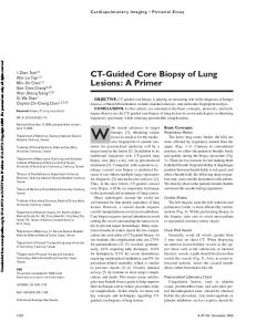
(2) Fig.1. Model of PMSM in a stationary frame
where J is the inertia of the motor and coupled load, Tl is the load torque, B is the friction coefficient and / P is the mechanical angular speed, ω is the electrical angular speed. The model of the PMSM in a stationary frame is discribed by following equations: dis us Rs is Ls dt P r sin e ; dis u R i L P r cos e ; (3) s s s s dt
3 Te 2 P r is sin e is cos e
The parameters shown in Table 1 correspond to a real motor RSM-36-550-25 that has been used in the simulation models. Table 1. Parameters of motor and load
where usα , usβ , isα and isβ are respectively the motor voltages and currents in α-β coordinates. Regarding the motor parameters ψs, ψr are respectively the flux of stator and the flux of the permanent magnet, P is the number of pole pairs, Rs is the stator resistance and Ls is the stator inductance. Te is the electromagnetic torque, e P , θ is angle of vector flux ψr and angle of rotor roration. The model of PMSM in a stationary frame is shown in Fig.1.
Output Power (Pn) Supply voltage (U) Number of pole pairs (P) Nominal Torque (Tn) Nominal Current (In) Stator resistance (Rs) Stator inductance (Ls) Permanent Magnet Flux (ψr)
5265W 540 V 48 345 N∙m 11,3 A 2.6 Ohm 26.2 mH 0,52 Wb
The inertia of motor (J1 ) Load torque (Tl)
5,31 kg∙m2 100 N∙m
The considered electric drive is constructed on the basis of a three-phase PMSM, controlled by transistors of the inverter using signals of position sensor. This optical encoder provides measurement of the angle of rotation and speed. The currents in motor windings are measured by current sensors. Generalized structure of PMSM with load shown in Fig.2 is used to calculation controllers’ coefficients.
Fig.2. Generalized structure scheme of PMSM with load
ISBN: 978-1-61804-299-6
27
Recent Advances in Electrical Engineering
3. Two-mass load
4. Field oriented control
Analysis of the position drives, robots, and other high-performance drive leads to the conclusion that they can with sufficient accuracy be described by a model of a two-mass system with elastic coupling, and, if necessary, with the nonlinear friction and backlash. In our case, the kinematic scheme of the mechanical part of the drive system can be represented as shown in Fig. 1.
The dynamic model of the PMSM presented in a rotating d-q frame fixed to the magnetic axis of the rotor is described by the following equations: Lsi r (4) sd sd sq Lsisq (5)
di Rs i Ls sd Lsisq (6) sd sd dt disq usq Rs isq Ls Lsi r (7) sd dt 3 Te P isq sqi (8) sd sd 2 where ψsd , ψsq , usd , usq , isd and isq are respectively the motor fluxes, voltages and currents in d-q coordinates. In order to understand the torque production, (8) can be rewritten to obtain an expression of the torque as a function of the stator flux and the PM flux: 3 Te P s r sin (9) 2 Ls It can be seen from (9) that the torque produced depends on the amplitude of the stator flux, the PM flux and the angle δ between both fluxes. It can also be concluded that maximum torque is produced when the angle between both fluxes is 90 degrees. The principle of FOC is using rotating vectors (or phasors) in a complex coordinate system. Similarly to the IM, in the PMSM a decoupled control of the torque and flux magnitudes can be achieved, emulating a DC motor, by means of the FOC strategy. The magnitude and the phase of the controlled current are changed [5]. This is done using the d-q transformation that separates the components d and q of the stator current responsible for flux and torque production respectively. Due to the presence of the constant flux of the permanent magnet, there is no need to generate flux by means of the isd current, and this current can be kept to a zero value isd =0, which in turns decreases the stator current and increases the efficiency of the drive. Fig. 5 describes the equations (6), (7) in the form of a vector diagram. u
Fig.3. Kinematic scheme of the engine load, where 1 – the input side of the motor shaft driven by electromagnetic torque, 2 - the output side with controlled plant, 3 - torsion spring with stiffness coefficient c12 and damper 4. Two-mass mechanical system comprises a lumped inertia of motor J1 and a load J2 coupled by a inertialess shaft with finite stiffness. The movement of both masses is described by angular speed 1 , 2 and angles 1 , 2 , respective. The drive system affect following torques (Fig.4.): - load torque which is called "dry friction torque" T T sign( ) , T T sign( ) . l2 L2 2 l1 L1 1
- torque of elastic coupling T12 - wind load torque Tw f w (t )
Fig.4. Block scheme of the two-mass load. For calculation of controllers’ coefficients, twomass load is replaced to one-mass load as shown in Fig.2. Here J =J1+J2.
ISBN: 978-1-61804-299-6
28
Recent Advances in Electrical Engineering
2 [isa sin(e ) isb sin e ] 3 3 2 isq [isa cos(e ) isb cos e ] 3 3 i sd
(11)
Block dq→abc performs the inverse transformation. The compensation block of cross-relation (BC) provides the following signals:
1
uc sd K
Ls isq
INV
1 usq Ls i r sd K INV
c
Fig.5. Vector diagram in rotating d-q frame The fact that the torque can be controlled by means of isq comes from the following simplification of (4),(8), valid for Surface Mounted (SM) PMSM: 3 Te P r isq (10) 2
(12)
a) Current loop (isd control) Fig. 7 shows the block diagram of the current control in closed loop.
5. Field oriented control based on voltage model of motor The control scheme of the FOC strategy based on voltage model of motor (6)-(7),(10) is shown in Fig. 6
Fig. 7. Current loop block diagram Current loop is tuned with help PI controller on magnitude optimum with the time constant T _id = TINV related with the delay of inverter according to the expressions: L / 2K INV K I TINV s K R / 2K INV K I TINV I _ id s
K
where K
inv
P _ id
(13)
- amplification factor of the inverter,
K I - feedback coefficient.
So system’s close loop transfer function: Fig. 6. The control scheme of the FOC strategy in the system with PWM inverter
Gid ( s)
For control of position servo drive system, it is proposed to use a four-loop cascade control structure with a position loop, speed loops and currents loop. Block abc→dq is used to transform real currents of windings iα, ib, ic to isd isq , which are dc quantities in the synchronous rotating frame:
1/ K I 1/ K I (14) 2TINV s 2TINV s 1 2TINV s 1 2
2
b) Current loop (isq control) In order to tune the PI current regulator in q axis, it can be followed the same procedure described, but in this case using compensation signal c usq
1 Ls i r . So isq current loop is sd K INV
tuned with help from the PI controller on magnitude
ISBN: 978-1-61804-299-6
29
Recent Advances in Electrical Engineering
optimum with the same values for KP_iq, KI_iq (see Equation 13). c) Internal and external speed loops Taking into account the Expression 10 and transfer function of inner current loop (14), one can obtain a block diagram of speed loops that is shown in Fig. 8
The result of simulation of four-loop FOC system of PMSM based on voltage model of motor is shown in Fig.12.
6. Field oriented control based on current model of motor The structure of the FOC strategy based on current model of motor (10) is shown in Fig. 9. This FOC strategy is realized with help CurrentRegulated pulse-width modulated (CRPWM) inverter.
Fig. 8. Current loop block diagram The magnitude optimization method is used for tuning internal and external speed loops. Internal speed loop is used P controller with coefficient K
P_s
where T
_s
( J1 J 2 ) K / (2T K ) I _s
(15)
1/ (2 ) is determined from the 0r
implementation of the bandwidth
0r
/ 4 3 . 0
C (J J ) 12 1 2 - mechanical resonant 0 J J 1 2 frequency of two-mass load and ( J J ) / J . 1 2 1
Fig.9. FOC with Current-Regulated pulse-width modulated (CRPWM) inverter
Here
The principle of operation of the CRPWM inverter and transient process in it are shown in Fig.10.
External speed loop is used I controller with coefficient: K
I _s
1 / (4T ) _s
(16)
d) Position loop Symmetric optimization method is used for position loop of control scheme with the PIcontroller. Coefficients of PI position controller are determined as: / (8T K ) _s . K K / (16T ) I _ P_ _s K
P_
K
(17) Fig.10a. The principle of operation of the CRPWM inverter
The transfer function of the closed loop position control in accordance with the configured controllers is: W
(4T 1) (18) * 3 3 (8T s 8T2 s 2 4T s 1) K
where T 4T _ s .
ISBN: 978-1-61804-299-6
30
Recent Advances in Electrical Engineering
Fig. 12. shows the closed-loop response in FOC PMSM system to the step reference signal and step load torque. Note that the process in the FOC with PWM inverter is slower than in the FOC with CRPWM inverter. Overshoot can be reduced by using a filter with transfer function
G filter ( s )
1 . 4T s 1
. Fig.10b. Transient process in the CRPWM inverter If the CRPWM inverter is ideal or has sufficiently large switching frequency that ia ia* , i i* , ic ic* and the structure shown in Fig. 9 is b b transformed to the structure in Fig. 11. In this Figure PMSM is presented by current model of motor which is a part of voltage model of motor in d-q coordinates with condition isd =0.
Fig.12. Transient processes in the FOC system with CRPWM inverter and in the FOC system with PWM inverter Fig.11. Equivalent structural scheme FOC with CRPWM inverter
Fig. 13 gives the result of the position regulation which illustrates tuned controllers can provide good control to realize the tracking to desired angle position in two-mass system.
Coefficients of PI position controller and P and I speed controllers are determined based on the structure of Figure 11 according to the expressions: - internal speed loop with P controller (exponential process with the smaller time constant T _ s ): K P1_ s 2 J / (3 P r KT _ s )
(19)
-external speed loop with I controller (magnitude optimum): (20) K 1 / (2T ) I 1_ s _s -position loop with PI controller optimum): K / (4T K ) P1_ _s . K K / (8T ) I 1_ P_ _s
(symmetric
K
Fig.13. Tracking mode in the two-mass FOC systems, where 1 – reference position signal, 2 – position signal in FOC system with currentregulated-PWM inverter, 3 - position signal in FOC system with PWM inverter
(21)
The transfer function of the closed loop position control is the same as Wϑ(s) in expression (18), but
T 2T _ s .
ISBN: 978-1-61804-299-6
31
Recent Advances in Electrical Engineering
[8] Yu.A. Bortsov, G.G. Sokolovskiy, Automatic Electric with elastic ties, Saint-Petersburg, Energoatomizdat, 1992.
7. Conclusion The paper presents a description and comparison two vector control strategies for PMSM drives: FOC in the system with current-regulated-PWM inverter and FOC in the system with PWM inverter and their use in the tracking servo drive system. A step by step method of controllers’ tuning is given. In position tracking PMSM servo drive system position loop and two speed loops are used. Internal speed loop is tuned to provide the bandwidth / 4 3 related with mechanical resonant 0r 0
frequency of two-mass load. The simulation results have been given based on the tuned controllers that show the good position regulation performance on tracking the desired position of PMSM. Using FOC with current-regulated-PWM inverter allows one to accelerate the transition process and also reduce the overshoots on reference following especially under the action of load torque. The Government of the Russian Federation, Grant 074-U01, financially supported this work
References: [1] C. Beards, Vibration analysis and control systemdynamics, Halsted Press, 1981. [2] R. Krishnan, Electronic Motor Drives: Modeling, Analysis and Control, Upper Saddle River, New Jersey, USA: Prentice Hall, Feb. 2001. [3] V.A. Tolmachev, Synthesis of the electric servo axes of positioned, Scientific and Technical Journal «Priborostroenie», vol. 51, no. 6, 2008, pp. 68-72. [4] G.L. Demidova, S.Yu Lovlin, M.Kh. Tsvetkova, Synthesis of Follow-up Electric Drive of telescope’s azimuth axis with reference model in position contour, Vestnik IGEU, no. 2, 2011, pp. 77–81. [5] G.L.Demidova, D.V.Lukichev, Fuzzy Control of the Position Servo Motor Drives with Elasticity and Friction, Proceedings of the 18th International Conference on Systems (part of CSCC '14) vol.1 pp. 157-160 [6] Blaschke F., The principle of field-orientation as applied to the transvector closed-loop control system for rotating-field machines, Siemens Rev., vol 34, pp. 217-220, 1972. [7] Bayer K.-H., Waldmann H., Weibezahl M. Die TRANSVEKTOR-Regelung für den feldorientierten Betrieb einer Synchronmaschine, SiemensZeitschrift, 45 (1971), S. 765–768.
ISBN: 978-1-61804-299-6
32