Recent Advances in Manufacturing Engineering
Effect of interactive normal and lateral Stiffness, damping and tip dimensions on the flexural and torsional vibration modes of rectangular AFM cantilevers MEHDI SHEKARZADEH, ABBAS RAHI Department of Mechanical Engineering Ahvaz Branch, Islamic Azad University Farhangshahr, Ahvaz IRAN
[email protected];
[email protected]
Abstract: - In this paper the effect of interactive normal and lateral stiffness, damping and tip dimensions on the flexural and torsional vibration modes of an AFM1 rectangular cantilever is analyzed. A clossed-form expression for the sensitivity of vibration modes is derived using the relationship between the resonant frequency and contact stiffness of cantilever and sample. Each mode has a different sensitivity to variations in surface stiffness. This sensitivity directly controls the image resolution. It is obtained an AFM cantilever is more sensitive when the contact stiffness is lower and the first mode is the most sensitive mode.
Key-Words: - Atomic Force Microscope (AFM), Vibration analysis, Flexuaral vibration, Torsional vibration, Cantilever al [1], the effects of damping on the vibration response of an AFM cantilever is significant and can not be disregarded. Also some of studies that considered the interactive damping, neglated the dimensions of the tip [5]. In this paper, we considered both of normal and torsional damping and also stiffness and damping in longitudinal direction and also the dimensions of the tip, then sensitivity and resonant frequency of the flexural and torsional vibration of an AFM cantilever were analyzed.
1 Introduction The atomic force microscope (AFM) extends the high resolution capabilities of the scanning tunnelling microscope, and is now widely used for imaging the surface topography of conductors and insulators on an atomic scale [1]. An atomic force microscope uses a cantilever beam (probe) with a sharp tip at the free end of it to place the tip close proximity to the surface of a sample. The deflection of the probe, due to the interaction between the tip and the specimen is measured and used to map the topography or other properties of the surface and specimen. When the tip scans across a sample surface, it induces a non-linear tip-sample interaction force, that its analysis can help to increase the resolution of surface images. For convenient analysis, in general, the interaction force is assumed to be a linear model. In the few last years, many researches have studied the vibration response of an AFM cantilever, but for convenience only considered the interactive stiffness between the cantilever and the sample surface and neglated the interactive damping [2-4], but as shown by Chang et
1
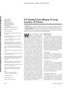
2 Analysis In this paper the atomic force microscope cantilever is considered as a rectangular elastic beam with uniform cross-section that has a length L , thickness b , and width a , as shown in Fig.1. It is fixed at x = 0 , while at x = L , has a conical tip. The tip has a length h , mass m and the distance between the lower edge of the cantilever and the centroid of the cross-section is hc . The tip interacts with the
Atomic Force Microscope
ISBN: 978-1-61804-031-2
57
Recent Advances in Manufacturing Engineering
sample by linear springs k n , kt , kl and dashpots
y(x,t) = (a1 coskx+ a2 sinkx+ a3 coshkx+ a4 sinhkx)eiωt (6)
c n , ct , cl . For normal interaction k n , c n and for lateral interaction kt , ct , kl and cl .
Where ai , i=1-4, are constants determined from the boundary conditions, ω is the angular frequency, k is the flexural wave number. From the above equations, the characteristic equation can be found:
mh 2 γ 3 C = γ 3 1 − c 3 (sinh γ cos γ + cosh γ sin γ ) + cos γ cosh γ ρ AL
1 mγ 4 2 − β n + ic n Lγ − ρ ρ EI A AL mhc 2γ 3 (1 − cosh γ cos γ ) − sin γ cosh γ + cos γ sinh γ = 0 3 ρAL
(7)
Fig.1: Schematic diagram of an AFM cantilever in contact with a sample
Where γ = kL is the normalized flexural wave
kn is the normal stiffness ratio EI L3
2.1 Flexural vibration analysis The linear differential equation of motion for the flexural vibration of the cantilever beam with uniform cross-section, as shown by Weaver et al is [6]:
between the normal contact stiffness and that of the cantilever. With substituting Eq.(6) into Eq.(1), we have:
EIy ′′′′( x, t ) + ρAɺyɺ( x, t ) = 0
EIk 4 − ρAω 2 = 0
number, β n =
(1)
Where the primes and dots represent the corresponding derivatives with respect to space, x and time, t , respectively. E is the module of elasticity, I is the area moment of inertia, ρ is the volume density and A is the rectangular crosssectional area of the cantilever. The corresponding boundary conditions are:
Therefore the relationship between frequency and wave number is given by:
f =
γ2 2πL2
EI ρA
(9)
The flexural sensitivity of the cantilever can be calculated from the frequency, which can be measured. The sensitivity of the mode of the cantilever changes significantly for small variations of stiffness as the cantilever crosses the sample. The relationship between frequency f and normal
y (0, t ) = 0
(2)
y ′(0, t ) = 0
(3)
2 EIy ′′( L, t ) = −mhc ɺyɺ′( L, t )
(4)
contact stiffness β n can be expressed as:
EIy ′′′( L, t ) = k n y ( L, t ) + cn yɺ ( L, t ) + mɺyɺ( L, t )
(5)
df df dγ = d β n d γ dβ n
A general solution of Eqs. (1)-(5) can be expressed as:
ISBN: 978-1-61804-031-2
(8)
(10)
Differentiation of Eq. (7) with respect to β n yields:
58
Recent Advances in Manufacturing Engineering
∂C ∂β n dγ =− ∂C ∂γ dβ n And also differentiation of Eq. (9) to β n yields:
df γ = 2 dγ πL
EI ρA
2.2
(11) with respect
Gξϕ ′′( x, t ) − ρJϕɺɺ( x, t ) = 0
× 3γ 2
(15)
Where the primes and dots represent the corresponding derivatives with respect to space, x and time, t , respectively. ϕ is the angle of torsion, G is the module of shear, J is the polar moment of area, ρ is the volume density, ξ is the torsional parameter for rectangular bar and is given by:
(12)
So with substituting Eq.(11) and Eq.(12) into Eq.(10), we have:
df 1 = 2 dβn 2πL
Torsional vibration analysis
The linear differential equation of motion for the torsional of the cantilever beam with uniform crosssection, as shown by Weaver et al is [6]:
mhc 2γ 3 1 − cosh cos ( ) γ γ EI 2γ ρAL3 ρA − sinγ coshγ + cosγ sinhγ
1 3
b a
ξ = b 3a1 − 0.63
(16)
The corresponding boundary conditions are:
mhc 2γ 3 (sinhγ cosγ − coshγ sinγ ) 1− 3 ρAL + cosγ coshγ
ϕ (0, t ) = 0
( )
(17)
Gξϕ ′( L, t ) = −k t h 2ϕ ( L, t ) − ct h 2ϕɺ ( L, t ) − I xϕɺɺ ( L, t ) (18)
1 4m 3 γ − 2ic nγL − EIρA ρAL
Where
b I x = I + m (hc + ) 2 2
mhc γ ( ) 1 − cosh γ cos γ − sin γ cosh γ + cos γ sinh γ 3 ρAL 1 mγ 4 − β n + ic n Lγ 2 − EIρA ρAL 2 3
(19)
A general solution of Eq. (15) can be expressed as:
ϕ ( x, t ) = (α sin px )e iωt
(20)
Where α is constant determined from the boundary conditions, ω is the angular frequency, p is torsional vibration wave number. From above equations, the characteristic equation can be found:
−1
3mhc 2 γ 2 − γ 2 coshγ cosγ 2 sin sinh − γ γ 3 ρAL − sinhγ cosγ + coshγ sinγ
(13)
I γ2 1 C = γ cosγ + β t + ict h 2γ − x sin γ = 0 GξρJ LρJ The sensitivity of flexural vibration can be written in normal form as:
Sn =
df dβ n 1 EI 2 2πL ρA
ISBN: 978-1-61804-031-2
(21)
Where γ = pL is the normalized torsional wave
(14)
2 number, β t = k t h is the torsional stiffness ratio Gξ L between the torsional contact stiffness and that of the cantilever. With the same calculation as part 2.1
59
Recent Advances in Manufacturing Engineering
the relationship between frequency f and torsional contact stiffness
βt
can be expressed
as:
γ sin γ − (1 + β ) cos γ − t df Gξ 1 1 = sin γ ic t h 2 (sin γ + γ cos γ ) dβ t 2πL ρJ GξρJ Ix 2γ sin γ + γ 2 cos γ + L ρJ (22)
(
-1
The lateral contact stiffness was assumed as k l = 0.9k n . The damping effect of an AFM cantilever on the flexural sensitivity of three modes is shown in fig.2.
)
The sensitivity of torsional vibration can be written in normal form as St =
df d β t 1 2π L
(23)
Gξ ρJ
3 Results and discussion
Fig.2: The effect of damping on the normalized flexural modal sensitivity as a function of normal contant stiffness for an AFM cantilever.
In this paper, the sensitivity of the vibration modes of an AFM cantilever has been analyzed. The main purpose of this paper is to study the effect of tip dimensions and normal and lateral stiffness and damping on the sensitivity and resonant frequency of the vibration modes of an AFM cantilever. In order to know these effects, the AFM cantilever is considered as an elastic beam with uniform rectangular cross-section with below geometric and material parameters:
This figure shows when the value of β n is low, the sensitivity of damped status is lower than undamped status in each mode. The more the value of β n , causes the smaller damping effect. The sensitivity of first mode is greater than second and third modes, at lower values of β n . However, the sensitivity of first mode rapidly decreased when the normal stiffness ratio, β n , increased. When the value of β n is about 30 and 67, the sensitivities of first mode are about 0.091 and 0.037 respectively. After the first point the sensitivity of second mode is greater than first mode, and after the second point the sensitivity of third mode is greater than first mode. Also when β n = 210.6 , the sensitivity of second mode is about 0.042.
Table 1: The geometric and material parameters of the cantilever and tip Parameter Unit Value E , Module of elasticity Gpa 170 G , Module of shear Gpa 66.4 ρ , Volume density 2330 kg / m 3 µm L , Length 300 µm a , Width 50 µ m b, Thickness 2 µm h, Tip length 10 m, Tip mass kg 2 × 10 −13
c n , Normal damping coefficient ct , cl Lateral damping coefficient
ISBN: 978-1-61804-031-2
ns/m
10 −6
ns/m
10 −5
Fig.3 shows the normalized sensitivity of mode 1 as function of the normal contact stiffness for an AFM cantilever at various damping coefficient values. When the value of β n is very small, the flexural sensitivity of mode 1 is lower with a higher damping coefficient. The higher damping
60
Recent Advances in Manufacturing Engineering
coefficient can influence the large range of β n
The normalized flexural sensitivities of mode 1 at various tip lengths, h, are shown in Fig.4. The effect of tip length is not very large, When β n has low
value. The more value of β n causes the smaller damping effect. The flexural sensitivity of AFM cantilever can be influence by boundary conditions. The tip length h and lateral cantact stiffness produce a moment M at the free end. The moment can change the sensitivity of the cantilever.
values, but as β n reached about 100, increasing the tip length increases the sensitivity. For torsional vibration, the same results were obtained. For example The damping effect of an AFM cantilever on the torsional sensitivity of three modes is shown in fig.5.
Fig.3: Comparison of the normalized flexural sensitivity of mode 1 as a function of normal contact stiffness for various normal damping coefficients. Fig.5: The effect of damping on the normalized torsional modal sensitivity as a function of torsional contact stiffness for an AFM cantilever.
4 Conclusion According to the analysis, it is obtained that, for an AFM cantilever, the first mode is the most sensitive mode of flexural and torsional vibration, while when the contact stiffness is greater, the high-order vibration modes are more sensitive than the first mode. The effects of the tip length on the sensitivity are significant and are not negligible when the contact stiffness is greater.
References: [1] W.J Chang, T. Fang and H. Chou, Effect of interactive damping on sensitivity of vibration modes of rectangular AFM cantilevers, Elsevier, Physics Letters, A 312, 2003, pp. 158165.
Fig.4: Normalized flexural sensitivity of mode 1 as function of the normal cantact stiffness for an AFM cantilever at various tip lengths.
ISBN: 978-1-61804-031-2
61
Recent Advances in Manufacturing Engineering
[2] H. Lee, W. Chang and Y. Yang, Flexural sensitivity of V-shaped cantilever of an atomic force microscope, Elsevier, Materials Chemistry and Physics, 92, 2005, pp. 438-442. [3] W.J Chang and S. chu, Analytical solution of flexural vibration responses on taped atomic force microscope cantilever, Elsevier, Physics Letters, A 309, 2003, pp. 133-137. [4] T.S Wu, W. Chang and J.Hsu, Effect of tip length on the flexural vibration responses of
ISBN: 978-1-61804-031-2
atomic force microscope cantilevers, Elsevier, Microelectronic Engineering, 71, 2004, pp. 15-20. [5] E. Rahman and A. Nayfeh, Contact force identification using the subharmonic response of a contact-mode atomic force microscopy, Insittute of Physics Publishing, Nanotechnology , 16, 2005, pp. 199-207. [6] Weaver W.J., Timoshinko S., Young D.H, Vibratuon problems in engineering, 5th edition, Wiley New Yourk, 1990.
62