The Nucleus 51, No. 2 (2014) 259-274
e Nucleus Th
The Nucleus A Quarterly Scientific Journal of Pakistan Atomic Energy Commission
NCLEAM, ISSN 0029-5698 Pa
ki sta n
REACTIVE POWER CONTROL OF WIND FARM USING FACTS DEVICES *
SARA ASHFAQ, A. ARIF, A. SHAKEEL and T. MAHMOOD
Department of Electrical Engineering, University of Engineering and Technology, Taxila, Pakistan (Received February 03, 2014 and accepted in revised form May 23, 2014) Wind energy is an attainable option to complement other types of pollution-free green generation Grid connections of renewable energy resources are vital if they are to be effectively exploited, but grid connection brings problems of voltage fluctuation and harmonic distortion. FACTs devices are one of the power electronics revolutions to improve voltage profile, system stability, and reactive power control and to reduce transmission losses. The studied system here is a variable speed wind generation system based on Induction Generator (IG) with integration of different FACTs controllers in the wind farm. To harness the wind power efficiently the most reliable and expensive system in the present era is grid connected doubly fed induction generator. Induction generator with FACTs devices is a suitable economical replacement. The suggested scheme is implemented in MATLAB Simulink with real time parameters of GHARO wind power plant in Sind, and corresponding results and output waveforms proves the potential strength of proposed methodology. Keywords: FACTs (Flexible AC transmission system), DFIG (Double Fed Induction Generator), PCC (Point of Common Coupling)
1.
Introduction
The AC transmission system has various limits classified as static limits and dynamic limits. These inherent power system limits restrict the power transaction, which lead to the under utilization of the existing transmission resources. Traditionally, fixed or mechanically switched shunt and series capacitors, reactors and synchronous generators were being used to solve much of the problem. However, there are restrictions as to the use of these conventional devices. Desired performance was not being able to achieve effectively. Wear and tear in the mechanical components and slow response were the heart of the problems. There was greater need for the alternative technology made of solid state devices with fast response characteristics. The need was further fuelled by worldwide restructuring of electric utilities, increasing environmental and efficiency regulations and difficulty in getting permit and right of way for the construction of overhead transmission lines. This, together with the invention of Thyristor switch (semiconductor device), opened the door for the development of power electronics devices known as Flexible AC Transmission Systems (FACTS) controllers [1]. The path from historical Thyristor based FACTS controllers to modern state-of-the-art voltage source converters based FACTS Controllers, was made possible due to rapid advances in high power semiconductors devices. FACTS controllers have been in use in utilities around the world since 1970s, when the first utility Corresponding author :
demonstration of first family of FACTS named as Static VAR Compensator (SVC) was accomplished. Since then the large effort was put in research and development of FACTS controllers. The history of development of these devices is presented alongwith the information regarding the first utility installation/ demonstration of FACTS devices [2]. A comprehensive collection of major FACTS installations around the world is then presented. The first FACTS installation was at the C. J. Slatt Substation in Northern Oregon. This is a 500 kV, 3-phase 60 Hz substation, and was developed by EPRI, the Bonneville Power Administration and General Electric Company [3]. There are some basic terms to describe wind electricity production. 1.1
Wind Efficiency
It refers to how much useful energy (electricity, in this case) we can get from an energy source. A 100 percent energy efficient machine would change all the energy put into it into useful energy. Wind machines are just as efficient as most other plants, such as coal plants. Wind machines convert 30-40 percent of the wind’s kinetic energy into electricity. The studied system has efficiency about 36.12%. 1.2
Wind Capacity Factor
It refers to the capability of a power plant to produce electricity. Wind plants depend on the availability of wind, as well as the speed of the wind. Therefore, wind machines cannot operate 24 hours a day, 365 days a year. A wind turbine at a typical wind farm operates 65-
[email protected]
Reactive power control of wind farm using FACTs devices
259
The Nucleus 51, No. 2 (2014)
80 percent of the time, but usually at less than full capacity, because the wind speed is not at optimum levels. Therefore, studied system has capacity factor of 30-35 percent. By capacity factor we mean its actual annual energy output divided by the theoretical maximum output, if the machine were running at its rated (maximum) power during all of the 8766 hours of the year.
1.4
Effect of Altitude on Wind Speed
The winds aloft generally have a higher velocity than the winds at ground level. In other words, at any given time and place, wind speed usually increases with altitude. The effect of altitude on wind speed involves two factors: The degree of turbulent mixing prevailing in the atmosphere at the given time and place, as characterized by the Pasqual stability class
Example: If a 600 kW turbine produces 1.5 million kWh in a year, its capacity factor is = 1500000: (365.25 * 24 * 600) = 1500000: 5259600 = 0.285 = 28.5 per cent.
The terrain's surface area roughness, which induces surface friction at the given place It has generally been agreed that the effect of altitude on wind speed is logarithmic and can be expressed as:
Capacity factors may theoretically vary from 0 to 100 per cent, but in practice they will usually range from 20 to 70 per cent, and mostly be around 25-30 per cent.
uz / ug = (hz / hg)a
1.3
where:
Wind Energy Production
Wind generated electric power output at Gharo has been estimated by using the 600kW wind turbine Bonus 600/40 MK IV type. The cut-in wind speed of turbine is 3m/s and cutout wind speed is 25m/s. Rotor diameter is 44 meters and hub height has been taken as 50 meter. The monthly and annual wind generated electric power output at Gharo-Sind along with capacity factor are given in Table and the month-wise hourly wind power output is given below. Table 1.
uz =wind velocity at height z ug = wind velocity at ground station height hz=height z hg=ground station height (usually 10 meters) a= a function of the Pasquill stability class and the terrain type (see tables below) Table 2.
Location
PMD Calculator (using 50M)
260
Value of a with respect to air humidity level.
Hypothetical wind generated electric energy output & capacity factor for a 600/44MK turbine.
Unstable air above open water surface
0.06
Neutral air above open water surface
0.10
Months
Capacity Factor
kWh per Month
January
13%
57745
Unstable air above flat open coast
0.11
February
16%
65384
Neutral air above flat open coast
0.16
March
16%
69869
Stable air above open water surface
0.27
April
30%
127689
Unstable air above human inhabited areas
0.27
May
60%
268240
Neutral air above human inhabited areas
0.34
June
45%
194703
Stable air above open coast
0.40
July
68%
305321
Stable air above human inhabited areas
0.60
August
35%
157142
September
43%
187858
October
12%
53867
November
10%
44324
December
13%
59327
Annual
28%
1495808
2.
System Model
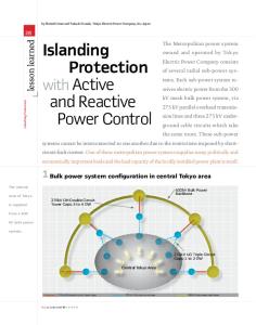
The models used in Matlab simulink are used for making model diagram. Different blocks are connected to get the complete block diagram. Some of these blocks are common in block diagrams of all FACTS devices like grid model, transformer model PI section, wind turbine induction generator model and grounding transformer. Their detailed description is as follows.
Sara Ashfaq et al.
The Nucleus 51, No. 2 (2014)
Grid 132KV
Mutual inductance
Transformer 132v/20kv
73 km Transmission line
Wind farm 18Mw
Grounding Transformer
FACTS Controller
Figure 1.
Figure 2.
3.
Model diagram for simulation.
Ideal shunt compensator.
“A power electronic-based system and other static equipment that provide control of one or more ac transmission system parameters.” Transmission systems are being pushed closer to their stability and thermal limits while the focus on the quality of power delivered is greater than ever [4-7]. The limitations of the transmission system can take many forms and may involve power transfer between areas or within a single area or region. 4.
4.3 Compound Compensator
FACTS Controller
Classification of FACTS
FACTS controllers can be broadly classified into these types: 4.1
Shunt Compensator
4.2
Series Compensator
Reactive power control of wind farm using FACTs devices
4.1
Shunt Compensator
A device that is connected in parallel with a transmission line is called a shunt compensator; these are referred to as compensators since they compensate for the reactive power in the ac system. We shall assume that the shunt compensator is always connected at the midpoint of transmission system, while the series compensator can be connected at any point in the line and it improves [8-9]. Voltage profile Power-angle characteristics Stability margin Damping to power oscillations
261
The Nucleus 51, No. 2 (2014)
The ideal shunt compensator is an ideal current source. We call this an ideal shunt compensator because we assume that it only supplies reactive power and no real power to the system. 4.2
Series Compensator
A device that is connected in series with the transmission line is called a series compensator.
controllable voltage source. Two inverters, namely shunt inverter and series inverter which operate via a common dc link with a dc storage capacitor, allow controller to independently control active and reactive power flows on the line as well as the bus voltage. Table 3.
Classification of FACTS.
Shunt Compensators
Impact of Series Compensator on Voltage Profile
STATCOM (Static Synchronous Compensator)
Improving Power-Angle Characteristics An Alternate Method of Voltage Injection
Series Compensators
Comparisons of the Two Modes of Operation In series compensation, the FACTS are connected in series with the power system. It works as a controllable voltage source. Series inductance exists in all AC transmission lines. On long lines, when a large current flows, this causes a large voltage drop. To compensate, series capacitors are connected, decreasing the effect of the inductance Series FACTS devices could be variable impedance, such as capacitor, reactor, etc., or power electronics based variable source of main frequency, sub synchronous and harmonic frequencies (or a combination) to serve the desired need. In principle, all series FACTS devices inject voltage in series with the transmission line [10-14]. It generates controllable voltage over an identical capacitive and inductive range independent of line current. It also provides real and reactive power injection to the line. Hense damping Oscillations and Voltage Stability is improved.
SSSC (Static Synchronous Series Compensator) TCSC Thyristor Controlled Series Compensator
Improving Stability Margin
Power Flow Control and Power Swing Damping
SVC (Static VAR Compensators)
TSSC Combination of Parallel and Series Compensators
UPFC (Unified Controller )
Power
Flow
IPFC ( Inter-phase Power Flow Controller) Other FACTS Controllers
TCPAR (Thyristor Control Phase Angle Regulators) TCVL (Thyristor Voltage Limiters)
Controlled
TSBR (Thyristor Breaking Resistors)
Switched
TCPST (Thyristor Controlled Phase Shifting Transformers)
In our system we have used following three controller SVC STATCOM UPFC 4.3.1
SVC (Static VAR Compensator)
“SVC is a shunt connected static VAR generator/load whose output is adjusted to exchange capacitive or inductive current so as to maintain or control specific power system variables.”
Figure 3.
4.3
Schematic Diagram of an Ideal Series Compensated System.
Compound Compensator
In compound compensation, the FACTS are connected in a combination of series and parallel connections with the power system. It works as a 262
The Static VAR Compensator (SVC) is a shunt device of the Flexible AC Transmission Systems (FACTS) family using power electronics to control power flow and improve transient stability on power grids [15]. The SVC regulates voltage at its terminals by controlling the amount of reactive power injected into or absorbed from the power system. When system voltage is low, the SVC generates reactive power (SVC capacitive). When system voltage is high, it absorbs reactive power (SVC inductive) [16]. The variation of reactive power is performed by switching three-phase capacitor banks and inductor banks connected on the secondary side of a coupling transformer. Each Sara Ashfaq et al.
The Nucleus 51, No. 2 (2014)
capacitor bank is switched on and off by three thyristor switches (Thyristor Switched Capacitor or TSC). Reactors are either switched on-off (Thyristor Switched Reactor or TSR) or phase-controlled (Thyristor Controlled Reactor or TCR). 4.3.2
STATCOM
“STATCOM is the voltage-source converter, which converts a DC input voltage into AC output voltage in order to compensate the active and reactive needed by the system.” With the advancement in the power electronic technology, the application of a gate turn off thyristor (GTO) to high power application became commercially feasible. With this the second generation shunt compensator device was conceptualized and constructed. These devices use synchronous voltage sources for generating or absorbing reactive power. A synchronous voltage source (SVS) is constructed using a voltage source converter (VSC). Such a shunt compensating device is called Static Compensator (STATCOM) [17]. If θ=Φ, then the direction of the flow of purely reactive current Iq will depend on the voltage magnitudes V1 and V2. If V1 > V2 then the current flows from the ac system to the SVS and the converter absorbs reactive (inductive) power. If V2 > V1 then the current flows from the SVS to the ac system and the converter generates reactive (capacitive) power for the ac system. However, pure reactive injection or absorption is neither possible nor desirable. Since the converter is supplied by a dc capacitor, the voltage across the capacitor will fall if the STATCOM is not lossless. The dc capacitor voltage can be regulated by replenishing the losses due to switching and in the coupling transformer circuit by drawing power from the ac system.
Therefore Φ must lag θ by a small amount such that the dc capacitor voltage is held constant. 4.3.3 UPFC (Unified Power Flow Controller) Two inverters, namely shunt inverter and series inverter which operate via a common dc link with a dc storage capacitor, allow UPFC to independently control active and reactive power flows on the line as well as the bus voltage. The UPFC has two voltage source inverters (VSI) sharing a common dc storage capacitor. It is connected to the system through two coupling transformers. The UPFC combines together the features of two FACTS devices: the Static Synchronous Compensator (STATCOM) and the Static Synchronous Series Compensator (SSSC) [18]. The DC terminals of the two underlying VSCs are now coupled, and this creates a path for active power exchange between the converters. Hence, the active power supplied to the line by the series converter, can now be supplied by the shunt converter. The UPFC can be used to control the flow of active and reactive power through the line and to control the amount of reactive power supplied to the line at the point of installation.
Figure 5.
Unified power flow controller.
While operating both inverters as a UPFC, the exchanged power at the terminals of each inverter can be imaginary as well as real.
Figure 4.
Working of STATCOM.
Reactive power control of wind farm using FACTs devices
The UPFC is a device which can control simultaneously all three parameters of line power flow (line impedance, voltage and phase angle).[19-20] The UPFC combines together the features of the Static Synchronous Compensator (STATCOM) and the Static Synchronous Series Compensator (SSSC). In practice, these two devices are two Voltage Source Inverters (VSI’s) connected respectively in shunt with the transmission line through a shunt transformer and in series with the transmission line through a series transformer, connected to each other by a common dc link including a storage capacitor. 263
The Nucleus 51, No. 2 (2014)
AC sourse 220V
2nd source (low Voltage)
Stepdown T/F
load
LCD Display
FACTs device
Figure 6.
Hardware block diagram.
Figure 7. SIMULINK environment.
5.
Hardware Implementation
A small scale model is developed to show the advantage of using FACTs device with the Wind farm induction generator. FACT device STATCOM is used in this scheme to implement the proposed strategy. In this model STATCOM is used for reactive power compensation at PCC. This model consists of following Components. 5.1
Generator
Since it can’t be possible to implement Generator that’s why for small scale implementation Generator is modeled as AC source of 220V. 5.2
So that it can be used like another generator giving less supply as that of an original Ac source. 5.3.
STATCOM
It is modeled as TRIAC with capacitor. TRIAC is bidirectional so current can flow through them in either direction .The impact of this device on steady state voltage and transient voltage stability is remarkable. 5.4
Inductive and Capacitive loads
Inductive and capacitive loads are used to check the performance of STATCOM in and out. In case of lagging voltage it provides reactive power and in case of leading voltage it absorbs it.
Wind Farm
Wind farm is modeled as another voltage source with Step down Transformer to reduce the voltage level.
264
Sara Ashfaq et al.
The Nucleus 51, No. 2 (2014)
5.5
Step Down Transformer
Step down transformer is used to step down the voltage level from AC source which represents the wind Farm. VCC VCC
10k
11 1
2
LCD 3
22pF 13
1k 14
12MHz
13 12 11
1
6
5
4
30 29 14
28 27
22pF VCC
21 20 19
7805
P1
1k
1k
16F877A
1000µF
1K
MOC 3026
BT136
104 10k AC1
P1
220
~ +
N
AC2
P2
10k
6KV ~
-
103
1000µF
0.22
2 10k
VCC
N
N
1k
3
~
-
Auto Transformer
1000µF
~ +
N
10µF 17 12
10k
C.T 204 1:90 LOAD
N
Figure 8.
5.6
Circuit diagram of hardware.
It is used for the automatic injection or removal of STATCOM. It works on the principle that when voltage is deviated from the certain limit it gives a signal to STATCOM into the circuit and to improve the voltage profile and voltage stability. 5.7
Capacitors
Microcontroller
Interfacing of Microcontrollers
Microcontroller is interfaced with the following components : LCD Voltage Regulator (7805) Opto Coupler (250/400 v) Bridge Current Transformer (1:90) TRIAC BT136 ( 4A) Auto Transformer LEDs Reactive power control of wind farm using FACTs devices
Resistors 5.8
Explanation
At first Ac source give a supply of 220V. The voltage and power factor will be displayed on LCD. The 220 v is step down to 6v Ac, which is converted to DC by the Bridge. The input from CT is also supplied to microcontroller through Bridge. The three inputs are given to microcontroller in the form of voltage at pin no 2, 3 and 17. Voltage, current and Phase angle is calculated. Then Step down transformer is used to reduce the voltage level from AC source which represents the IG wind Farm. Inductive load is used to consume some of its voltage, so there is voltage drop requiring the STATCOM to be in. So LCD displays “Applying STATCOM “. STATCOM is used for Reactive power compensation, when V is high it absorbs the Reactive power from the system and when V is low it supplies the reactive power to the system. 265
The Nucleus 51, No. 2 (2014)
Thus Stability is maintained in the System. LCD is used for voltage and power factor display. So Voltage
Figure 9.
6.
Wind Potential Area
Pakistan Meteorological Department has conducted a detailed Wind Power Potential Survey of Coastal Areas of Pakistan This study has enabled us to identify the potential areas where economically feasible wind farm can be established. Potential areas cover 9700 sq.km in Sind. The gross wind power potential of this area is 43000 MW and keeping in view the area utilization constrains etc. the exploitable electric power generation potential of this area is estimated to be about 11000MW. Feasibility study for the installation of 18 MW Model wind power project is prepared. Total cost of the project is estimated to be about Rs. 850 million and the payback period would be 7-8 years. The levelised cost of power generation is estimated as Rs. 2.9/kwh. 7.
Case Studies
Following case Studies have been performed on test case. 266
and power factor is improved Power factor approaches to almost 0.999.
Hardware Model.
7.1. Reactive power Investigations without Controller 7.2. Reactive power Investigations with STATCOM at 80 m altitude 7.3. Reactive power Investigations with STATCOM at 60 m altitude 7.4. Reactive power Investigations with SVC at 80m altitude 7.5. Reactive power Investigations with SVC at 60 m altitude 7.6. Reactive power Investigations with UPFC at 80 m altitude 7.7. Reactive power Investigations with UPFC at 60 m altitude 7.1
Without ontroller
The simulation results without any reactive power compensation device are given below: Sara Ashfaq et al.
The Nucleus 51, No. 2 (2014)
Figure 10.
Figure 11.
7.2
Simulation of Grid without Controller.
Simulation Result of Wind Turbine without Controller.
STATCOM Controller With STATCOM at 80 m
Figure 12.
Simulation Result of Grid with STATCOM at 80m Height.
Reactive power control of wind farm using FACTs devices
267
The Nucleus 51, No. 2 (2014)
Figure 13.
Simulation Result of Wind Turbine with STATCOM at 80m Height.
Figure 14.
7.3
With STATCOM at 60 m
Figure 15. 268
Simulation Result of STATCOM.
Simulation Result of Grid with STATCOM at 60m Height. Sara Ashfaq et al.
The Nucleus 51, No. 2 (2014)
Figure 16.
Simulation Result of Wind Turbine at 60m Height.
Figure 17. Simulation Result of STATCOM.
7.4
SVC Controller
With SVC at 80m Using svc in wind power plant doesn’t affect too much. The voltage and the reactive profile almost
Figure 18.
remains the same. There is a very small regulation through svc. So it is not recommended to use svc for voltage and reactive power regulation in wind power plant.
Simulation Result of Grid with SVC at 80m Height.
Reactive power control of wind farm using FACTs devices
269
The Nucleus 51, No. 2 (2014)
Figure 19.
Simulation Result of Wind Turbine with SVC at 80m Height.
Figure 20.
7.5
With SVC at 60m
Figure 21.
270
Simulation Result of SVC
Simulation Result of Grid with SVC at 60m Height.
Sara Ashfaq et al.
The Nucleus 51, No. 2 (2014)
Figure 22.
Simulation Result of Wind Turbine with SVC at 60m Height.
Figure 23.
7.6
Simulation Result of SVC.
UPFC Controller With UPFC at 80m
Figure 24.
Simulation Result of Grid with UPFC at 80m Height.
Reactive power control of wind farm using FACTs devices
271
The Nucleus 51, No. 2 (2014)
Figure 25.
Simulation Result of Wind Turbine with UPFC at 80m Height.
Figure 26.
7.7
With UPFC at height of 60m
Figure 27. 272
Simulation Result of UPFC.
Simulation Result of Grid with UPFC at 60m Height. Sara Ashfaq et al.
The Nucleus 51, No. 2 (2014)
Figure 28.
Simulation Result of Wind Turbine with UPFC at 60m Height.
Figure 29.
Simulation Result of UPFC.
The UPFC is versatile and multifunction power flow controller with capabilities of terminal voltage regulation, series line compensation and phase angle regulation. Besides the above mentioned functions, UPFC has additional features making it very popular among the available FACTS devices. But cost of FACTs devices varies proportionally with size, as size of UPFC is large in comparison to others. So it is expensive to use. 8.
Discussion
The use of STATCOM is to control the voltage by exchanging reactive power with the grid, but their capability to exchange active power is very limited due to the small energy that can be stored in a conventional DC capacitor attached with it. A STATCOM can give additional benefits, such as increased capability to damp electro-mechanical oscillations increased power quality and reliability of supply. The results have shown that Reactive power control of wind farm using FACTs devices
the STATCOM device has the ability to significantly reduce the power fluctuations generated by a wind farm comprising induction generators, and the voltage profile has been improved, while also keeping the voltage at the PCC in limit. In addition, the Wind Farm's fault ride through capability can be greatly improved by the STATCOM. This would allow a comparison between a wind farm using fixed speed induction generators combined with a STATCOM, and wind farms using DFIGs which inherently generate fewer flickers due to the smoothing effect of the rotor with variable speed. 9.
Conclusion
The basic operation of IG and FACTs controller has been discussed. A Wind Farm test case is simulated with integration of different FACTs controller namely SVC, STATCOM and UPFC at different wind altitudes.
273
The Nucleus 51, No. 2 (2014)
It has been observed that Using SVC in wind power plant doesn’t affect too much. The voltage and the reactive profile almost remains the same. So it is not recommended to use svc for voltage and reactive power regulation in wind power plant. The use of STATCOM is to control the voltage by exchanging reactive power with the grid. The results have shown that the STATCOM device has the ability to significantly reduce the power fluctuations generated by a wind farm comprising induction generators, and the voltage profile has been improved, while also keeping the voltage at the PCC in limit. The Unified Power Flow Controller (UPFC) is a second generation FACTS device, which enables independent control of active and reactive power besides improving reliability and quality of the supply. The UPFC is versatile and multifunction power flow controller with capabilities of terminal voltage regulation, series line compensation and phase angle regulation. But cost of FACTs devices varies proportionally with size, as size of UPFC is large in comparison to others. So use of STATCOM is recommended.
[10] S. Haddad, A. Haddouche, and H. Bouyeda International Journal of Computer and Electrical Engineering 1, No. 1 (2009) p.71.
9.
References
[1]
N. Hingorani, Flexible AC transmission Spectrum 30, No 4 (1993) p.40-45.
[14] Naruttam Kumar Roy, M. J. Hossain, Student Member, IEEE, and H. R. Pota .Voltage Profile Improvement for Distributed Wind Generation using D-STATCOM.IEEE Trans.2011.p.3-5
[2]
Y.H. Song and A.T. Johns, IEE Power and Energy Series, The Institute of Electrical Engineers (IEE) Press 30 (1999) p. 310-317
[3]
B.A. Renz, A. Keri, A.S. Mehraban, C. Schauder, E. Stacey, L. Kovalsky, L. Gyugyi and A. Edris, IEEE Trans. PD 14, No. 4 (1999) p.1374.
[4]
C.R. Fuerte-Esquivel, E. Acha, H. Ambriz-Pe´rez, IEEE Trans. Power Systems 15, No. 1 (2000) 58.
[5]
IEEE
R.M. Mathur and R.K. Varma, Thyristor, Based FACTS Controllers for Electrical Transmission Systems, John Wiley & Sons, Inc. and IEEE Press.
[6]
Electrical Machines, Drives and Power Systems, 6th Edition (2005) p. 820.
[7]
K. Venkateswararao and P.K. Agarwal, 16th National Power Systems Conference, Department of Electrical Engineering, Malaviya National Institute of Technology, Jaipur, India, 15th-17th December (2010).
[8]
W.H. Kersting, Distribution System Modeling and Analysis, Boca Raton, FL CRC (2002).p.145-163
[9]
K.M. Rogers, Student Member, IEEE, and T.J. Overbye, Fellow, IEEE , Smart-Grid -enabled load and distributed generation as a reactive resource, In proceeding of: Innovative Smart Grid Technologies (2010) p 7
274
[11] F.B Alhasawi, J.V. , Economic Viability of Application of FACTS Devices for Reducing Generating Costs, IEEE Power and Energy Society General Meeting (2010) p. 1-3. [12] F.B. Alhasawi, J.V. Milanović, Alabduljabbar, Correlation Between Uncertainties in System Model Parameters and Distribution of Critical Electromechanical Modes, Power Generation, Transmission, Distribution and Energy Conversion, 7th Mediterranean Conference and Exhibition (2010). [13] A. B.Bhattacharyya and B. S.K.Goswami, World Academy of Science, Engineering and Technology 5 (2011) 2. IEEE Transactions on Power Delivery, Proposed Terms and Definitions for Flexible AC Transmission System 12, No. 4 (1997) 1848.
[15] H.M.H. Tani, Dept. of Electrical and Electronics Eng. Meiji University, A Tabu Search Based Method for Optimal Allocation of D-FACTS in Distribution Systems. Proceedings of the 17th World Congress, The International Federation of Automatic Control Seoul, Korea, July 6-11 (2008) p. 14951-14954 [16] A. WA. Bose, USA New Smart Grid Applications for Power System Operations, IEEE Power and Energy Society General Meeting (2010) p.4. [17] X.P. Zhang, A Framework for Operation and Control of Smart Grids with Distributed Generation IEEE Power and Energy Society General Meeting - Conversion and Delivery of Electrical Energy in the 21st Century (2008) p.1-3. [18] X. Fang, G. Xue, Smart Grid – The New and Improved Power Grid: A Survey, Communications Surveys & Tutorials, IEEE 14, No. 4, p 950-956 [19] Rolf Grünbaum, Member, IEEE , FACTS for Grid Integration of Wind , Innovative Smart Grid Technologies Conference Europe (ISGT Europe), IEEE PES (2010) p. 3-8.
Sara Ashfaq et al.