NORPIE 2004 Trondheim, Norway
1
Voltage Regulator for Reactive Power Control on Synchronous Generators in Wind Energy Power Plants Balduino Rabelo 1) , Wilfried Hofmann, Member, IEEE Abstract—This paper presents a voltage regulator for the field circuit of a separately excited synchronous generator in wind power plants. A hydrodynamic variable speed planetary gear is used to maintain constant speed on the generator shaft. The generator is directly connected to the net without power electronics . This new concept promises better power quality and do not need bulky output filters. In order to fulfil new requirements on wind generation units the field voltage controller must present some features like reactive power and dynamical stability control. The used model and the design procedures, as well as some simulation results are shown
2)
, Martin Tilscher 3) , Andreas Basteck
4)
1. Support net voltage during fault conditions; 2. Control reactive power in a desired range; 3. Limit maximum generated power; 4. Limit start -up current transients.
Index Terms—Renewable energy systems, control of electrical drives, powerquality.
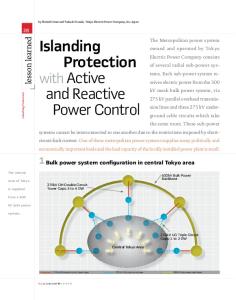
I. INTRODUCTION Recent studies have shown that the most used electrical generators in wind power plants are the doubly-fed induction generator, the gear-less synchronous generator and the squirrel-cage induction generator, respectively [1]. Although separately excited synchronous generators with small number of poles are not so popular in this field, a new horizon is opened for them when the shaft speed is maintained constant mechanically. This goal is achieved with a hydrodynamic controlled variable speed gear (Vorecon) from the Voith Company. The Vorecon keeps the output shaft speed to the generator constant while the input shaft speed from the turbine is variable. This enables the direct connection of the synchronous generator stator circuit to the mains supply without needing a power electronics converter to correct voltage and frequency. This improves the power quality and does not require the bulky output LC-filter, reducing losses and weight. Further advantage of this topology is the high efficiency of the system, since the Vorecon presents losses compared to a controlled electrical machine over the whole speed range. The system overview with the planetary gear and the hydraulic torque converter connecting the turbine and generator is shown in figure 1. In order to fulfil the new guidelines from the power companies throughout Europe for connection of wind energy conversion systems to the high-voltage net, depicted in [2], an induced voltage controller is designed and presented in this study, as well as some simulation results. For this new generation of wind power stations there are four basic requirements from the power company:
Fig.1 – System overview.
The first, second and fourth part of the 4. requirements must be fulfilled through the excitation controller. The first item is described in the norms as the voltage drop profile of figure 2 on the high- voltage net connection point (NCP). The generator must not be turned off if the voltage level is above it. This point has been discussed by wind mill operators and machine constructors. For a single generator support the voltage loss depicted in figure 2 the value of the required internal induced voltage would make the generator production costs impracticable. Furthermore the field circuit and exciter had to be over-dimensioned increasing the machine size.
Fig.2 – Voltage Drop Profile.
NORPIE 2004 Trondheim, Norway
2
Taking into account the short -circuit impedances of the transmission and distribution lines and of the transformer between the machine terminals and the faulty point the voltage level would increase by the voltage drop over the equivalent impedance. Normally more generating units are connected to the same NCP, so that supporting the voltage or feeding the fault would be shared through these plants. To accomplish this task the excitation regulators must be interconnected by a master monitoring system that coordinates the control actions of the sole generators. Controlling the reactive power and synchronising with the mains supply are normally built-in functions of the field exciter for commercial synchronous generators over a few hundred kilowatts. For wind generation applications one must have in mind that the prime mover is depending on the stochastic wind speed variations. The pitch control is too slow to avoid completely the torque disturbances caused by wind gusts. The guide vane actuates faster in a limited operating range. The combination of these two controllers enables a good operation of the wind station in an appropriate range. Nevertheless, the field controller must guarantee dynamical stability of the system under extreme conditions.
Fig.3 – Block diagram of the synchronous machine model.
The differential equation of the field circuit is given by the following expression
u f = Rf if +
d ψ . dt f
(2)
In order to consider the effects of the damping circuit the following flux equations in frequency domain are introduced.
ψ sd ( s ) = GL ( s )isd ( s ) + G f ( s )u f ( s ) ψ sq ( s ) = GLq ( s )isq( s ) d
A 2.5 MW separately excited synchronous generator connected to the wind turbine by a variable speed planetary gear was modelled and the voltage regulator was designed. These were then simulated under some normal condition operations, like synchronisation, input power step and reactive power step. Detailed explanation about the modelling and design of the machine and controller are given on the further topics.
where the equations of the transfer functions Gf (s) , GLd (s) , and G Lq (s) , as functions of the generator inductances and time constants, are derived in the literature [1,2] and shown by expressions (4), (5) and (6), respectively.
GLd ( s ) = Lsd
II. M ACHINE MODEL AND CONTROLLER A. Machine Modelling A classical model of a separately excited synchronous machine with damping circuit in a synchronous rotating dqcoordinate was utilised [3,4]. The basic stator equations in time domain are shown below.
d u sd = R sisd + dt ψ sd − ω rψ sq usq = R sisq + d ψ sq + ω rψ sd dt
generator shaft.
GLq ( s ) = Lsq
Gf ( s ) =
(1)
where ψ are the fluxes and ωr is the angular speed of the
(3)
s 2Td' Td'' + s (Td' + Td'' ) + 1 s 2Td' 0Td''0 + s (Td' 0 + Td''0 ) + 1
1 + sTq'' 1 + sTq''0
(4)
(5)
Lsd − L' sd Td' 0 L f 1+ sTd' 0
(6)
These expressions model all the interactions between the different circuits on a synchronous machine. The electromagnetic torque expression as a function of the stator currents and fluxes is done by (7).
Te =
(
3 Z p ψ sd isq − ψ sqi sd 2
)
(7)
where Zp is the number of pole pairs. Figure 3 shows the block diagram of the machine model.
NORPIE 2004 Trondheim, Norway
3
Further modifications have to be carried out in the model structure from figure 2 in order to represent a non-connected machine before synchronisation. This situation is described by the equations (8) and (9) where the machine with no currents and induced voltages at the terminals is modelled.
e = d ψ − ωψ r sq sd dt sd d esq = ψsq + ωrψsd dt
applied to the main generator field circuit. This is the preferred type for high-powered machines. The proposed controller structure can be applied to any generator type and do not present an inner current controller. This can be further implemented and improves the dynamical response of the system. The structure is depicted in figure 4.
(8)
e is the induced voltage. If the field flux is constant and different from zero and regarding equations (3) and (8) one can derive the following expression.
ψf = ψsd = cte. ⇒ ψ& sd = 0 esd = 0 ⇒ ψ = 0 ⇒ ψ& = 0 sq sq esq = ωrψf
Fig.4 – Reactive power and synchronisation controllers.
(9)
which depicts the real situation before synchronisation. The voltage at the machine terminals equals the internal induced voltage on the quadrature axis. Both non-connected and connected model were built in the same simulation block and interchanged at the synchronisation moment. B. Controller Design In order to accomplish the electrical requirements, like reactive power control for example, a control algorithm for regulating the field voltage and so the induced voltage on the stator windings was developed and simulated. This controller has to carry out the following tasks: regulate the induced voltage at the machine terminals during synchronisation while the prime mover controls the speed and position, control the power factor or the reactive power flow during normal operation and guarantee the dynamical stability of the machine during undesired transient conditions, like voltage drops and input or output power steps. Here some comments must be done about the field excitation circuit type. The basic configurations use slip-rings or are brushless types. The first one can be self-excited, where the terminal voltage supplies the field controller on the machine stator side. After rectification and signal processing the output excitation voltage is passed to the field circuit through the sliprings. Another variant posses a rotating rectifier bridge in the rotor feeding the field circuit directly after signal processing on the stator side. The brushless types carry out the control tasks on the stator side and the output current feeds the field circuit of an auxiliary machine mounted on the same shaft of the main generator. This exciter induces voltages in the rotating armature coils that are rectified by a diode bridge converter also mounted on the rotor side. The rectified voltage is then
This controller delivers the reference value of the excitation voltage of the field circuit Uf by controlling the induced voltage on the stator circuit UPol. The reference value for this latter is the mains voltage un before synchronisation. After the machine is connected, the power factor controller is activated and generates a ∆un value that is subtracted (or added) to the original reference supply voltage. This enables the generator to work under- or over-excited, controlling the reactive power flow. Under faulty conditions the controller is blocked and the excitation voltage chosen is proportional to the voltage drop and to the active and reactive powers flowing on the moment of the fault. A stability controller working in parallel with the original structure was implemented later and improved the performance of the machine during non-synchronous operation. Further computations of the static and dynamic stability under faulty conditions will give precise information for an optimal control. The induced voltage regulator was designed using linear control techniques and posses 2 different controllers for before and after synchronisation. The plant structure on the closedcontrol loop can be seen on figure 5.
Fig.5 – Induced voltage closed loop control.
The 2 regulators are projected based on optimal module (BO) and symmetrical optimum (SO) design techniques. The first one has the net voltage as reference value before synchronisation. The second regulator is put in operation after synchronisation and receives some variation of these reference value from the power factor controller, as seen before in fig. 4.
NORPIE 2004 Trondheim, Norway
4
The frequency response of the open and closed-loop control using both regulators is shown in figure 6.
00..55 00..44 II
aa bb cc
00..33
Bode Diagram
//II
nn
150 150
Magnitude (dB)
00..22
BO BO open open B BO O cclloosseedd SO SO open open S SO O cclloosseedd
100 100 5500
00..11 00
00
--00..11
--5500
--00..22
-100 -100 00
--00..33 --00..44
Phase (deg)
--4455 --00..55 11..22
--9900
11..2255
11..33
11..3355 tt (( ss ))
11..44
11..4455
Fig.7 – Start-up currents during synchronisation.
-135 -135 -180 -180 1100
--22
00
1100
22
1100
Frequency (Hz) 44
xx 1100 00
Fig.6 – Bode diagram of the open and closed loop induced voltage control.
--00..55 --11
The SO designed regulator was made faster in order to catch up stepwise changes of active and reactive power without losing synchronism. This is observed by the higher corner frequencies on the dashed and dotted-dashed curves. Furthermore, stability is guaranteed for both control loops, as shown on the open-loop phase margin curves. The power factor controller was calculate by the optimum damping criteria (DO) after linearizing the plant over the operation point. The power angle instead of the power factor was used as controlled variable as it presents a more linear characteristic over the desired range and provides the information of under- or over-excited operation by its sign.
--11..55 m m --22
aa
(( N Nm m ))
--22..55 --33 --33..55 m m --44
ee
(( N Nm m ))
--44..55 55
55..55
66
66..55 tt (( ss ))
77
77..55
88
Fig.8 – Input torque step
33
III. SIMULATION RESULTS Some simulation results of synchronisation, active and reactive power steps are shown. Connecting the machine to the mains with an angle error from less than 10 degrees gives the transient currents observed in figure 7. The peak values lie under 40 % of rated value and the transients vanish in less than one second. Further low frequency oscillations of the speed are also observed. Figures 8 and 9 show an input torque step from 0 to rated torque and the respective current overshoot due to the increase on the power input. Even with the extreme power step the generator is kept in synchronism and the currents reach the rated value after the transient period. Figures 10 and 11 bring an active power step input and the effect on the power factor control
II
22
//II aa bb cc
nn
11
00
-- 11
-- 22
-- 33 55
55..55
66
66..55
77
77..55
88
tt (( ss ))
Fig.9 –Phase currents overshoot during an input power step.
.
NORPIE 2004 Trondheim, Norway
5
44
--11..22
44
xx 1100
-0.8 -0.8
xx 1100
--11
--11..33
-1.2 -1.2
m m
ee
((N Nm m))
--11..44 m m
ee
(( N Nm m ))
-1.4 -1.4
--11..55
-1.6 -1.6
--11..66
-1.8 -1.8 m m
--11..77
aa
(( N Nm m ))
m m
aa
((N Nm m))
--22 -2.2 -2.2
--11..88 -2.4 -2.4 --11..99
-2.6 -2.6
--22
-2.8 -2.8
--22..11 2266
2277
2288
2299
3300
3311
3322
3333
tt (( ss ))
0.4 0.4 S Siinnuuss P Phhii 00..3355
C Cooss P Phhii 00..9922 iinndd 0.3 0.3
00..2255
0.2 0.2 C Cooss P Phhii 00..9988 iinndd
2277
2288
2299
3300
3311
3322
3333
t(s)
Fig.11 –Cross-coupling with the reactive power control.
Once again over-shoots on the electromechanical torque occur during the transient period. These could be better damped with a proper selection of the controller gains or with an active damping procedure. Of course a compromise must be met concerning the stability. The coupling with the reactive power control can be observed on the power factor in figure 11. The well-damped controller reduced the over-shoots and let the actual value reach the reference smoothly after some seconds. 0.4 0.4 S Siinnuuss P Phhii 0.3 0.3
Cos Cos Phi Phi 0.92 0.92 ind ind
0.2 0.2 0.1 0.1 00 -0.1 -0.1 -0.2 -0.2 -0.3 -0.3 -0.4 -0.4 3333
C Cooss P Phhii 00..9922 kkaapp 3333..55
3344 t(s)
3344..55
Fig.12 – Reactive power step.
3333..55
3344 tt((ss))
3344..55
3355
Fig.13 –Cross-coupling with the active power.
Fig.10 – Negative input torque step.
00..1155 2266
--33 3333
3355
Figures 12 and 13 show the effect of a reactive power step on the active power or electromagnetic torque. It is remarkable here that the coupling from the reactive power canal with the active power. The increase on the torque caused by the reference power factor step is less damped than the reaction caused again on the powe r factor. This extreme reactive power step must be avoided in the normal operation of the generator. Faulty conditions reproducing the voltage profile from figure 2 on the machine terminals were also simulated but not shown here. In order to keep the machine in stable operation without loss of synchronism the field circuit must over-excite the machine and so experience higher voltages and currents. With a non-saturated model the voltage on the field circuit had to be increased until six times the rated value, which would be impracticable. These results will point out in a further work the stability margin that could be reached by controlling the field voltage.
IV. CONCLUSIONS The machine classical model has to be adapted to simulate situations before synchronisation. A voltage regulator for the field excitation of a synchronous machine is proposed. This controller has to guarantee stable operation of the generator under various conditions including faults. Simulation results show the good performance of the controller. With the already existing controller the machine is kept stable during extreme conditions like torque steps and reactive power variations. Faulty conditions were also simulated. Further studies will investigate the effects of faulty conditions on the mechanical drive train caused by high electromechanical torque and its harmonics and of the distribution line and the transformer on the performance of the machine under voltage drops.
NORPIE 2004 Trondheim, Norway
A CKNOWLEDGMENT The authors would like to thank the Voith company, the Chemnitz University of Technology and the company AEM for the financial and technical support of this work. REFERENCES [1] Rabelo, B., and Hofmann, W. “Optimal Reactive Power Splitting with the Doubly Fed Induction Generators for Wind-Turbine”, Proceedings of DEWEK’2002, CD. Wilhemshaven, Germany, October 2002. [2] Rabelo, B., Hofmann, W. “Wind Generator Control in Compliance with New Norms”, Proceedings of ISIE’2003, CD. Rio de Janeiro, Brazil, July 2003. H. Poor, An Introduction to Signal Detection and Estimation. New York: Springer-Verlag, 1985, ch. 4. [3] Kovács, K.P., Rácz, I. “Transiente Vorgänge in Wechsltrommaschinen”, Verlag der Ung. Akademie der Wisss. Budapest, Hungary, 1959. [4] Müller, G., “Betriebsverhalten rotierender elektrischer Maschinen”, VEB Verlag Technik, Berlin, 1990. J. Wang, “Fundamentals of erbium-doped fiber amplifiers arrays (Periodical style—Submitted for publication),” IEEE J. Quantum Electron., submitted for publication.
1)
Dipl.-Ing. Balduino Rabelo is with the Chemnitz University of Technology, Dept. of Electrical Machines and Drives, 09127 Chemnitz, Germany (corresponding author to provide phone: +49371-531-3586; fax: +49371-531-3324; e-mail:
[email protected]). 2)
Prof. Dr.. Wilfried Hofmann is the chair of the Dept. of Electrical Machines and Drives at the Chemnitz University of Technology phone: +49371-531-3323; (e-mail:
[email protected]). 3)
Dr. Martin Tilscher is with the Voith Turbo Company, Controlled Drives Department, 74564 Crailsheim, Germany (email:
[email protected]). 4)
Dr.Andreas Basteck is with the Voith Turbo Company, Controlled Drives Department, 74564 Crailsheim, Germany (e mail:
[email protected])
6