Control of the Reactive Sputtering Process Using Two Reactive Gases W.D. Sproul, D.J. Christie, and D.C. Carter, Advanced Energy Industries, Inc., Fort Collins, CO; and S. Berg and T. Nyberg, Uppsala University, Uppsala, Sweden Key Words:
Sputter deposition Partial pressure control
Reactive deposition Vacuum system instrumentation and control
ABSTRACT Reactive sputtering when two reactive gases are used presents special problems. Both reactive gases affect the plasma conditions, which means that both affect common feedback control signals such as the cathode voltage and optical emission signals. Two reactive gases require that unique signals for each reactive gas be acquired and that control of each of the reactive gases is done separately. Modeling has confirmed that the way to control the process when two reactive gases are present is to produce two individual single-valued parameters. For this process, the single-valued parameters for the partial pressures of the reactive gases can be supplied from a mass spectrometer or from an optical emission spectrometer (looking at individual gas lines). The reactive sputtering of titanium in a combined oxygen/nitrogen atmosphere using partial pressure control of each reactive gas is shown. A combination where one of the gases is controlled in partial pressure mode and the other in a flow mode can lead to unstable operating conditions. To gain stability of the process when two reactive gases are used requires that the partial pressure of each gas be controlled individually.
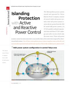
More recently, Berg et al. [13] have modeled two-gas reactive sputtering using combinations of flow and partial pressure control of each gas. Their work shows that there can be several processing points for a certain partial pressure when a combination of flow control is used for one of the gases and partial pressure control is used for the other gas as is shown in Figure 1. However when partial pressure control is used for each gas, there is only one processing point for each combination of the partial pressures as is shown in Figure 2.
INTRODUCTION Reactive sputtering is now commonly used to deposit compound materials formed from the reaction between the sputtered target material and a reactive gas. Closed-loop control of the reactive gas offers the advantage of high deposition rates and controlled compositions. Recently there has been interest in reactive sputtering using one target material and two reactive gases [1-5]. However, as has been shown by Berg and co-workers [6-8], reactive sputtering with two reactive gases is a more complex problem than sputtering with one reactive gas. They have shown that when mass flow control of the reactive gases is used, one gas may trap the target in the poisoned mode, and the only way to get out of this problem is to shut down both gases and start over. Martin and co-workers [9-12] have also studied two-gas reactive sputtering, and they have also observed the trapping effects that Berg and coworkers reported. Martin and Rousselot [9-10] also reported instability regions for two-gas reactive sputtering, and Martin and co-workers [11-12] have shown that pulsing of one of the gases provides the ability to deposit films with a wider range of compositions. 98
Figure 1: Results from the two-gas reactive sputtering Berg et al. model [13] showing a sudden change in the rate when one of the two reactive gases is controlled in the flow mode. In this paper, we experimentally verify that partial pressure control of each reactive gas is necessary to obtain process stability when two gases are used during reactive sputtering. Previously, work on two-gas reactive sputtering of AlNxOy was reported [2] in which it was shown that a combination of flow and partial pressure control can lead to trapping of the target in the poisoned mode. Partial pressure control of each gas avoided this problem. For studying two-gas reactive sputtering, there is an issue with AlNxOy. The AlOy system shows a distinct hysteresis curve, but AlNx does not. The partial pressure controlled hysteresis curve for AlNx is essentially a flat line, and it does not exhibit the characteristic Sshaped curve. For this study, the TiNxOy system was chosen because both components (TiNx and TiOy) have recognizable S-shaped hysteresis curves.
© 2003 Society of Vacuum Coaters 505/856-7188 46th Annual Technical Conference Proceedings (2003) ISSN 0737-5921
RESULTS AND DISCUSSION As a reference point, reactive sputtering hysteresis curves were generated for the titanium-nitrogen and titanium-oxygen systems. These two hysteresis curves are shown in Figure 3. The TiOx system takes a higher reactive gas flow than does the TiNx system before the start of the formation of the compound on the edges of the racetrack region of the target. The TiOx system also has a much larger change in flow from the metallic state to the fully poisoned target state of about 4 sccm compared to a change of about 0.5 sccm for the TiNx system.
Figure 2: Results from the two-gas reactive sputtering Berg et al. model [13] showing no sudden changes in the rate when the partial pressure of both gases is controlled.
EXPERIMENTAL CONDITIONS Two-gas reactive sputtering experiments were carried out in a medium-sized, open-volume, cylindrical vacuum chamber (0.75 m diameter x 0.45 m deep) using a 15-cm Kurt Lesker Torus 10 balanced-field magnetron. Prior to test depositions, the chamber was turbo-molecular pumped to base pressures below 1.33x10⁻⁴ Pa (< 1.0x10⁻⁶ Torr). The titanium target was sputtered using an Advanced Energy“ Pinnacle™ Plus pulsedDC power supply operating at a frequency of 100 kHz and a reverse time of 2.0 µsec (80% duty factor). The target power was 1.0 kW, and the argon sputtering pressure was 0.47 Pa (3.5 mTorr). The reactive gas partial pressure was controlled with an Advanced Energy® IRESS partial pressure control system utilizing a differentially pumped Inficon Transpector® 2 mass spectrometer for sensing the partial pressures of the reactive gases. Up to four gases can be monitored simultaneously during the reactive process and signals provided to indicate their level. Uniform distribution of reactive gases was achieved using simple diffusers. Individual hysteresis curves were generated for the titaniumnitrogen and the titanium-oxygen systems. For the two-gas reactive sputtering experiments, the admission of the reactive gases into the chamber was controlled in one of two ways. The first way was to set a fixed flow of one reactive gas while the partial pressure of the second gas was varied over a range of partial pressures. The second way was to control the partial pressure of each reactive gas individually, and within this method there were two variations. The first was to vary the partial pressures of both reactive gases as a ratio of one another, and the second way was to fix the partial pressure of one gas while the partial pressure of the second gas was varied.
Figure 3: Reactive sputtering hysteresis curves for the titanium-nitrogen and titanium-oxygen systems.
The hysteresis curve for the TiNx system is a very tight curve with the increasing and decreasing partial pressure curves sitting virtually right on top of each other. In contrast for all hysteresis curves generated so far for the TiOx system, there is a separation of the decreasing partial pressure curve from the increasing partial pressure curve. The exact reason for this separation is not fully understood at this time. In some cases, it has been observed from the mass spectrometer trace for the run that water vapor outgassing occurred. This water vapor cracked in the plasma supplying atomic oxygen, which would react readily with the titanium and reduce the amount of molecular oxygen flowing into the system needed to maintain the partial pressure. However in other cases, there was no indication of water vapor outgassing during the run. The separation of the increasing oxygen partial pressure curve from the decreasing one still occurred, but the amount of separation was decreased. This separation issue needs further investigation. Combined Partial Pressure and Flow Control of the Two Reactive Gases The Berg model [13] predicts that in certain situations when one gas is in flow control and the other in partial pressure control that there can be several processing points for a given 99
combination of the flow and partial pressure. To verify the prediction of the model, experiments were run with one reactive gas under partial pressure control and the other under mass flow control. For the case where the oxygen flow was set and the nitrogen partial pressure was varied, three different oxygen flows of 5, 7, and 9 sccm were chosen, which represent points at low, medium, and high flows on the titanium-oxygen hysteresis curve. Once the oxygen flow was set, varying the nitrogen partial pressure generated a nitrogen hysteresis curve. At the low flow, the effect of the constant oxygen flow was to suppress the nitrogen flow needed to reach a given nitrogen partial pressure. The shape of the nitrogen flow/partial pressure curve is similar to the one shown in Figure 3. As the nitrogen partial pressure was increased, there was a steady increase in the oxygen partial pressure. However, no abrupt changes in the oxygen partial pressure occurred. When the oxygen flow was increased to 7 sccm and the nitrogen partial pressure was varied, the nitrogen flow was suppressed even more compared to the 5-sccm situation. Oxygen is the dominant gas in this two-gas reactive sputtering situation, and it is consumed at a higher rate than the nitrogen. This difference in consumption of the two gases is due to the difference in free energy of formation of each of the compounds and to the difference in sputtering rates for the two materials. There is a major difference between the 5- and 7-sccm situations. When the nitrogen partial pressure reached a value of 0.16 Pa (1.2 mTorr) for the 7-sccm-oxygen flow condition, a cusp in the nitrogen flow-partial pressure curve occurred as shown in Figure 4. Concurrent with the drop in nitrogen flow at the cusp, there was a sharp increase in the oxygen partial pressure, as is shown in Figure 5, for the mass spectrometer trace for the run.
Figure 5: Mass spectrometer trace for the 7-sccm fixed oxygen flow and varying nitrogen partial pressure run showing the sudden increase of the oxygen partial pressure where it stayed for the remainder of the run.
When the nitrogen partial pressure was reduced back to its starting value, the flow of nitrogen decreased linearly, and there was no S-shaped curve. However during the reduction of the nitrogen partial pressure, there was no reduction in the oxygen partial pressure from the high value that it reached at the point of the cusp in increasing nitrogen flow-partial pressure curve. The combination of the oxygen flow and the nitrogen partial pressure fully poisoned the target, but upon reduction of the nitrogen partial pressure the oxygen flow was sufficient to trap the target in a poisoned mode and to keep the oxygen partial pressure high. For the case where the oxygen flow was 9.0 sccm, the combination of the oxygen flow and the initial nitrogen partial pressure was sufficient to cause immediate poisoning of the target. The oxygen partial pressure quickly jumped to a high value even though the nitrogen partial pressure was low. When the nitrogen flow was fixed and the oxygen partial pressure was varied, there were no discontinuities in the oxygen partial pressure curves as the nitrogen flow was increased. Figure 6 shows the results with fixed nitrogen flows as the oxygen partial pressure was varied. The effect of the nitrogen was to suppress the oxygen flow for a given oxygen partial pressure, but the shape of the oxygen flow/ partial pressure curve was not changed compared to the pure titanium/oxygen hysteresis curve.
Figure 4: The nitrogen flow/partial pressure plot for the reactive sputtering of TiNxOy with a fixed oxygen flow of 7.0 sccm. The effect of the fixed oxygen flow is to suppress the nitrogen flow for a given nitrogen partial pressure (see Figure 3) and to cause an abrupt change in the operating conditions at a nitrogen partial pressure of about 0.16 Pa (1.2 mTorr). 100
Figure 6: TiNxOy hysteresis. Oxygen flow as a function of the oxygen partial pressure for different fixed nitrogen flows. Only the increasing partial pressure portion of the oxygen curve is shown.
Partial Pressure Control of Both Gases—One Partial Pressure Fixed, the Second Varying Berg’s model [13] predicts that the only way to have continuity over the whole three-dimensional control surface when reactive sputtering with two reactive gases is to control the partial pressure of each gas. To verify this part of the model, two partial pressure conditions were evaluated—the first, where one partial pressure was constant while the second partial pressure was varied and, the second, where both partial pressures were varied.
Figure 7: TiNxOy hysteresis for three-fixed nitrogen partial pressures and varying oxygen partial pressures. Plot shows the oxygen and nitrogen flows as a function of the increasing oxygen partial pressure.
Varying Partial Pressure Control of Both Gases Experiments were run when the partial pressure of the second gas was set as a percentage of the first reactive gas. A typical curve showing the nitrogen and oxygen flow/partial pressure curves where the nitrogen partial pressure is 100% of the oxygen partial pressure is shown in Figure 8. The shape of the oxygen flow/partial pressure curve is preserved, and the flow is slightly reduced compared to when no nitrogen is present.
In the first part, the nitrogen partial pressure was set at 0.22, 0.33, and 0.44 Pa (0.029, 0.044, and 0.059 mTorr), and these values represent partial pressures around the peak of the nitrogen flow for the titanium/nitrogen reactive sputtering system. The oxygen partial pressure was varied between 0.012 and 0.24 Pa (0.09 to 1.8 mTorr). This upper partial pressure was chosen because it is well beyond the point where the target is fully poisoned, and any further increase in the oxygen partial pressure leads to a linear increase in the flow. The oxygen and nitrogen flows as a function of the oxygen partial pressure are shown in Figure 7 for the three fixed nitrogen partial pressures. There are several important points from this plot. The shape of the oxygen flow/partial pressure curve does not change. As the partial pressure of the nitrogen is increased, the oxygen flow needed to achieve a given partial pressure is reduced. Oxygen is the dominant gas, and its flow is reduced but not greatly. Conversely as the partial pressure of the oxygen is increased, the nitrogen flow falls off rapidly even though its partial pressure is fixed, reaching an asymptotic value by the time that the oxygen curve is about half way between the metallic state and the poisoned state.
Figure 8: TiNxOy hysteresis curves (for increasing partial pressure only) for equal partial pressures of nitrogen and oxygen. Even though the partial pressures are equal, oxygen dominates the reaction.
However, the nitrogen curve is a different situation. There is a slight dip in the nitrogen curve as its partial pressure is increased, but overall the flow values are greatly reduced compared to when no oxygen is present. Oxygen really dominates this two-gas reactive sputtering situation.
101
A series of flow/partial pressure curves for TiNxOy generated when the nitrogen partial pressure was 0, 25, 50, 75, and 100% of the oxygen partial pressure is shown in Figure 9. The overall effect of increasing the nitrogen partial pressure is to reduce the oxygen flow for a given oxygen partial pressure. Although not shown in this figure, all of the nitrogen flows are greatly reduced for a given nitrogen partial pressure compared to when no oxygen is present. In all cases, oxygen dominates the reaction when the nitrogen partial pressure is equal to or less than the oxygen partial pressure.
Figure 10: TiNxOy hysteresis curves where nitrogen is the major reactive gas. This composite plot shows the nitrogen flow/partial pressure curves (for increasing nitrogen partial pressures only) when the oxygen partial pressure is 0, 25, 50, 75, and 100% of the nitrogen partial pressure.
CONCLUSIONS
Figure 9: TiNxOy hysteresis curves where oxygen is the predominant reactive gas. This composite plot shows the oxygen flow/partial pressure curves (for increasing oxygen partial pressures only) when the nitrogen partial pressure is 0, 25, 50, 75, and 100% of the oxygen partial pressure.
When nitrogen is the predominate partial pressure during the two-gas reactive sputtering of TiNxOy, there is a similar set of flow/partial pressure curves for the nitrogen partial pressure as is shown in Figure 10. However, the effect of oxygen as the second gas is much stronger than what it was when nitrogen was a percentage of oxygen. There is a large drop in the nitrogen flow of about 4 sccm when the oxygen partial pressure is 25% of the nitrogen partial pressure. This result should be compared to the result shown in Figure 9 where a 25% partial pressure addition of nitrogen leads to about a 1 sccm drop in oxygen flow. In all cases investigated in this work, oxygen is definitely the dominant reactive gas.
102
Flow control of two-gas reactive sputtering is a more complex control problem than reactive sputtering with a single reactive gas. In this paper we have verified the predictions of the Berg model for two-gas reactive sputtering. When one gas is flow controlled and the other is partial pressure controlled, there will be multiple processing points for the same flow/partial pressure conditions. However when both reactive gases are partial pressure controlled, there are strong reasons to believe that there is only one processing point for each combination of the two partial pressures. Therefore we conclude that partial pressure control of both gases is required for successful stable and reproducible two-gas reactive sputtering. ACKNOWLEDGMENTS The authors are indebted to Karen Peterson for running the two-gas reactive sputtering experiments.
REFERENCES 1.
M. R. Visokay, J. J. Chambers, A. L. P. Rotondaro, R. Kuan, L. Tsung, M. Douglas, H. Bu, A. Shanware, and L. Colombo, “Properties of Hf-Based Oxide and Oxynitride Thin Films,” Proceedings of the 2002 AVS 3rd International Conference on Microelectronics and Interfaces, Santa Clara, CA, p. 127, February 11-14, 2002.
2.
W. D. Sproul and B. E. Sylvia, “Multi-Level Control for Reactive Sputtering,” 45th Annual Technical Conference Proceedings of the Society of Vacuum Coaters, Orlando, FL, p. 11, April 2002.
3.
J. Schulte and G. Sobe, “Magnetron Sputtering of Aluminum Using Oxygen or Nitrogen as Reactive Gas,” Thin Solid Films, 324, 19, 1998.
4.
J. Baborowski, M. Charbonnier, and M. Romand, “Effect of the Nature of the Working Gas on the D.C. Sputter Deposition of Chromium Nitride and Ox-Nitride Thin Films on Steel Substrates,” Surface and Coatings Technology, 80, 190, 1996.
5.
M. Serényi, M. Rácz, and T. Lohner, “Refractive Index of Sputtered Silicon Oxynitride Layers for Antireflection Coating,” Vacuum, 61, 245, 2001.
6.
P. Carlsson, C. Nender, H. Barankova, and S. Berg, “Reactive Sputtering Using Two Reactive Gases, Experiments and Computer Modeling,” J. Vac. Sci. Technol. A, 11(4), 1534, 1993.
7.
H. Barankova, S. Berg, P. Carlsson, and C. Nender, “Hysteresis Effects in the Sputtering Process Using Two Reactive Gases,” Thin Solid Films, 260, 181, 1995.
8.
S. Berg and C. Nender, “Modeling of Mass Transport and Gas Kinetics of the Reactive Sputtering Process,” Journal de Physique IV, Colloque C5, supplément au Journal de Physique II, 5, C5/45, 1995.
9.
N. Martin and C. Rousselot, “Instabilities of the Reactive Sputtering Process Involving One Metallic Target and Two Reactive Gases,” J. Vac. Sci. Technol. A, 17(5), 2869, 1999.
10. N. Martin and C. Rousselot, “Influence of Two Reactive Gases on the Instabilities of the Reactive Sputtering Process,” Surface and Coatings Technology, 142, 206, 2001. 11. N. Martin, R. Sanjinés, J. Takadoum, and F. Lévy, “Enhanced Sputtering of Titanium Oxide, Nitride, and Oxynitride Thin Films by the Reactive Gas Pulsing Technique,” Surface and Coatings Technology, 142, 615, 2001. 12. N. Martin, O. Banakh, A. M. E. Santo, S. Springer, R. R. Sanjinés, J. Takadoum, and F. Lévy, “Correlation between Processing and Properties of TiNxOy Thin Films Sputter Deposited by the Reactive Gas Pulsing Technique,” Applied Surface Science, 185, 123, 2001. 13. S. Berg, T. Nyberg, and W. D. Sproul, “A Study of the Reactive Sputtering Process with Two Reactive Gases,” to be submitted for publication to Surface and Coatings Technology.
103