CHAPTER 9
PRE-ENGINEERED STORAGE TANKS During World War II, steel tanks made possible many operations. During large operations, especially in forward areas, the need for rapid transport and appropriate storage facilities were of major importance. Steel tanks were used to store fuel, diesel oil, gasoline, and water to meet the demand for storage facilities. Ships and planes were supplied from secret tank farms at overseas bases, making possible many of the large invasions of the war in the Pacific.
re-erection kits that contain new gasket material and extra nuts and bolts. In disassembling a tank, however, workers should make an effort to save all of the items of hardware that can be used again. When taking down a tank, avoid damage to any of the members because the number of re-erections of a tank depend largely upon the care taken during dismantling.
This chapter will brief you on the procedures to follow in erecting bolted steel tanks including preparation of the foundation for a tank-
Exercise care when handling plates to avoid bending, dropping, or otherwise damaging the steel. Bent plates will cause problems when the tank is erected, and when used, the result is usually a leaking tank.
CAUTION
STEEL TANKS Many types of tanks are available. Besides tanks that are constructed of standard mild steel sheets, tanks of galvanized steel sheets and of wrought iron may also be obtained. Tanks may be bolted, riveted, or welded. Bolted and riveted tanks have capacities of up to 10,000 barrels. Welded tanks may hold as many as 50,000 barrels.
TANK FOUNDATIONS Considerable care should be taken in constructing the GRADE or finished foundation on which the tank is to be erected. Concrete foundations are ordinarily not necessary if the ground is reasonably hard. When the grade is properly prepared and perfectly level, the tank can be joined on an even surface, and, therefore, it is easier to fit up and erect the tank Also, with proper support, the completed tank will be less likely to leak.
Steelworkers are normally concerned with PREFABRICATED BOLTED TANKS. These tanks are composed of steel sheets of a size that is easily transported. Individual pieces are quite light. They can be assembled quickly in the field by crews of relatively untrained men so long as the man in charge understands the details of their construction. Once the tanks are assembled, they will last for 5 or 6 years or longer. A shipment includes all of the bolts, the nuts, the fittings, and the gasket material required for assembly. Drawings and assembly instructions also are provided.
Grading The earth grade should be constructed approximately 1 foot greater in diameter than the diameter of the tank which is to occupy it. The earth must be well-tamped to a firm and smooth surface. Never fill the area for a tank foundation because erosion will, in time, result in a faulty foundation.
Ten-thousand-barrel tanks are used to store fuel and diesel oil at overseas bases. One-thousand-barrel tanks are used for gasoline storage. Low 5,000-barrel tanks are seldom used for fuel storage where large operations are under way, but they may be used for storage of water. Since a barrel is equal to 42 gallons, you can see that a 10,000-barrel tank is capable of holding 420,000 gallons.
Foundation Construction The tank foundation should be dry, level, and well-drained. A layer of clean gravel or sand on the grade is ideal for this purpose. Tar paper may be spread under the tank as a corrosion-resistant carpet. When a layer of gravel or sand is used on a grade of firm earth, follow these steps:
If desired, bolted steel tanks can be dismantled and re-erected at another location. You can obtain
1. Drive a peg in the exact center.
9-1
2. Mark this center peg at a point 6 inches from the top) and drive it down in the grade to this mark.
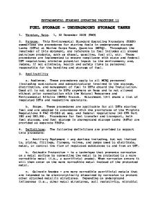
100-Barrel Tank The 100-barrel tank shown in figure 9-1 is the smallest bolted steel tank. It has a holding capacity of 4,200 gallons of liquid and is made up of preformed and punched metal sections, fastened together with l/2-inch-diameter bolts. The tank bottom (fig. 9-2) consists of two semicircular halves, bolted together at a lap joint along the center of the tank bottom. This vertical, bolted steel tank has a 9 foot 2 3/4-inch-inside diameter and is 8 feet 1/2 inch high at the sidewall.
3. Use a wooden straightedge with a carpenter’s level attached to set grade stakes about 10 feet apart. Note that, set in this manner, they will protrude 6 inches above the earthen grade. 4. Distribute sand over the whole grade, using shovels and rakes. When the sand just covers the top of each of the stakes and the center peg, the proper level has been reached. 5. Drive the stakes and the center peg all the way down into the earth under the sand. When the tank is filled, the sand will compact, and if the stakes are not driven down, they may cause leaks. Mark the position of the center peg with a temporary pin so that you will be able to position the center of the tank bottom later.
SIDE STAVES.— The side staves consist of six curved, vertical sections, arranged in a single ring. The staves are chimed (flanged) at the top and bottom of each section with the left end of each chime offset so the vertical seams overlap. The bottom chime bolt holes are patterned to match the outer edge bolt holes in the tank bottom. The vertical seams have one row of bolt holes.
6. To make the surface smooth, use a sweep with a carpenter’s level attached. Pin the sweep to the center peg and drag it over the sand, filling in any hollows and smoothing out humps. The sand pad should be at least 4 inches thick and should have a crown of about 1 inch in 10 feet of tank radius; however, the crown should not exceed 6 inches. When a foundation is properly prepared, many unnecessary problems do not occur during construction of the tank. Just imagine the problems that might occur, both in erection and in subsequent maintenance of a tank, if the’ foundation were to settle unevenly, throwing the steel plates on one side of the tank slightly out of line. Remember that the walls of the tank—consisting merely of steel plates bolted together-must act as bearing walls to support the roof. So, make sure you have a good foundation before starting to assemble a tank.
Figure 9-1.—100-barrel capacity, vertical, bolted steel tank.
BOLTED STEEL TANK ASSEMBLIES
Tanks are assembled by sections, consisting of pieces of various sizes and shapes that combine to form cylindrical structures. Among the most common are the bolted steel tanks, having a capacity of 100, 250, or 500 barrels of liquid Many tank sections serve the same function regardless of tank capacity. However, the number of sections used in each assembly will vary according to capacity. The procedures for assembling and erecting these tanks are similar.
Figure 9-2.—Tank bottom.
9-2
of the manhole attached to the top of the center ladder supports.
CENTER LADDER SUPPORTS.— The center ladder is the center support for the tank deck. The ladder is adjustable and is used to align the deck section bolt holes and provide the required slope to the tank deck
OUTSIDE LADDER.— Each tank is equipped with an outside ladder for access to the deck The ladder is bolted to the bottom and top chimes of a side stave and is usually located near a tank thief and vent.
The ladder consists of two ladder braces, two ladder rails, four ladder steps, steel angles, and a flanged manhole that supports the tank deck
250-Barrel Tank
TANK DECK— The tank deck is made up of six sections, extending radially from the tank center ladder support to the top chime of the single ring of side staves. Each deck section has an integral formed flange along its right edge when viewed from the large end toward the small end of the deck section. The flanged side of the deck section acts as a supporting rafter for the deck section. A bolt retainer angle is attached to the inside face of each deck section, flanged to retain the radial seam joint bolts that are installed near the right edge of each deck section.
The 250-barrel tank has a capacity of 10,500 gallons of liquid, and the fabrication is similar to the 100-barrel tank. The tank bottom consists of ten wedge-shaped plates, assembled radially around a one-piece center section, as shown in figure 9-4. The inside diameter is 15 feet 4 5/8 inches and is 8 feet 1/2 inch high at the sidewall. SIDE STAVES.— The side staves consist of ten curved, vertical sections, arranged in a single ring. The staves are chimed (flanged) at the top and bottom of each section with the left end of each chime offset so the vertical seams overlap. The bottom chime bolt holes are patterned to match the outer edge bolt holes in the tank bottom. The vertical seams have one row of bolt holes.
SPECIAL SECTIONS.— The tank bottom has one special section, fitted with a blind opening. All of the staves are special sections (fig. 9-3). One section is for a cleanout cover, and the other five sections are used for pipe connections. The tank deck has three special sections. One section is for a combination thief hatch and vent, one section has a blind hatch, and one section has a liquid level indicator.
TANK DECK.— The tank deck is made up of ten sections, extending radially from the tank center ladder support to the top chime of the single ring of side staves. Each deck section has an integral formed flange along its right edge when viewed from the large
EMERGENCY VENT.— Each tank is equipped with an 8-inch emergency vent, bolted to the top cover
Figure 9-3.—Layout of the staves around the tank bottom.
9-3
Figure 9-4.—Layout of the staves around the tank bottom, 250-barrel capacity tank.
combination thief hatch and vent, and one section is used for a liquid level indicator.
end toward the small end of the deck section. The flanged side of the deck section acts as a supporting rafter for the deck section. A bolt retainer angle is attached to the inside face of each deck section, flanged to retain the radial seam joint bolts that are installed near the right edge of each deck section.
EMERGENCY VENT.— An 8-inch vent is bolted to the top cover of the manhole attached to the top of the center ladder supports. 500-BarreI Tank
SPECIAL SECTIONS.— The tank bottom has one special section, fitted with a blind opening. Four of the ten staves are special sections. One section is for a cleanout cover, and the other three sections are used for pipe connections. The tank deck has three special sections. Two sections are used for a
The 500-barrel tank (fig. 9-5) has a capacity of 21,000 gallons of liquid and is similar to the 250barrel tank, except that the bottom consists of 14 wedge-shaped plates around a one-piece center section, as shown in figure 9-6. This vertical, bolted
Figure 9-5.—500-barrel capacity vertical, bolted steel tank assembled.
9-4
ERECTION OF A 500-BARREL TANK
steel tank has a 21 foot 6 l/2-inch-inside diameter and is 8 feet 1/2 inch high at the sidewall.
Although similar in design and construction, bolted steel tanks differ mainly in the number of parts required for each different size tank. Therefore, the erection procedures for the 500-barrel tank, described here, can be applied to the other tanks regardless of size.
SIDE STAVES.— The side staves consist of 14 curved, vertical sections, arranged in a single ring. The staves are chimed (flanged) at the top and bottom of each section with the left end of each chime offset so the vertical seams overlap. The bottom chime bolt holes are patterned to match the outer edge bolt holes in the tank bottom. The vertical seams have one row of bolt holes.
Center Bottom Plate The center bottom plate (fig. 9-7) is a circular, flat steel plate. The tank bottom plates are attached to the outer circumference bolting circle. Before installation of the center bottom plate, make sure that it is not warped or broken. Check the bolt holes for bolt clearance. Clean the bolt holes of dirt or other foreign material where the center plate gasket is applied. Drive the center stake below the surface of the foundation and backfill the hole. Place the bolt-retaining boards around the outer circumference of the plate. Position the plate over the center stake. Place the gasket around the bolt circle of the center bottom plate. Insert two 1/2- by 1 l/2-inch bolts in the two bolt hole channel.
TANK DECK.— The tank deck is made up of 14 sections, extending radially from the tank center ladder support to the top chime of the single ring of side staves. Each deck section has an integral formed flange along its right edge when viewed from the large end toward the small end of the deck section. The flanged side of the deck section acts as a supporting rafter for the deck section. A bolt retainer angle is attached to the inside face of each deck section, flanged to retain the radial seam joint bolts that are installed near the right edge of each deck section. The bolt retainer angle acts as a stiffening member to the deck section flange along the span of the deck section SPECIAL SECTIONS.— The tank bottom has one special section, fitted with a blind opening. Five of the 14 staves are special sections. One section is for a cleanout cover, and the other four sections are used for pipe connections (fig. 9-6). The tank deck has three special sections. Two sections are used for a thief hatch and relief valve, and one section is used for a liquid indicator. EMERGENCY VENT.— Each tank is equipped with a 10-inch emergency vent, bolted to the top cover of the manhole attached to the top of the center ladder supports.
Figure 9-7.—Installation of the gasket the bolts, and the channels on the center bottom plate.
Figure 9-6.—Layout of the staves around the tank bottom, 500-barrel capacity tank.
9-5
Insert the channel assembly through the center bottom plate and gasket.
applied to each end of the overlap strip to ensure a leakproof joint.
NOTE: To prevent damage to the gasket, do not use a sharp-edged tool or pipe to force the gasket over the bolts. Use a well-rounded, smooth, mouth tool.
Upon the completion of the assembly, move this plate to the approximate installation position on the tank foundation.
Lay the center bottom plate on the bolt-retaining boards. These boards will prevent movement of the bolts when the bottom plates are installed.
Of the 13 intermediate plates, one is an outlet plate, which is assembled with channels and strip gaskets. The channels are placed under the right lap seams. Follow the same assembly procedures as outlined above. In addition, the outlet plate has a blind flange set assembled on it. The above procedure does not apply to the last bottom plate as no further assemblies are made on it. Keep the last bottom plate separated from all of the other plates until it is installed in the tank bottom.
Bottom Plates The tank bottom consists of 14 tapered, flat steel plates. Thirteen plates are plain, and one is soecial. All of the plates are interchangeable. When the bottom is completely installed, the plate pattern resembles a wheel. The first bottom plate (fig. 9-7, #7) has a bolt channel placed under each radial lap seam with l/2by 1 l/4-inch bolts (fig. 9-8). A strip gasket is placed along each seam. The seams are identified as right and left, facing the large end.
Cut six one-hole gaskets from the strip gasket material (fig. 9-8, #2). Force a one-hole gasket over and against the head of each flange bolt. Insert the bolts through the bolt holes in the inside flange half from the outside face of the flange with the heads of the bolts fitting into the cutouts provided. Lay bolt-retaining boards on the ground. Position the flange assembly with the bolt head resting on the boards. Slip a gasket over the bolts and force it down against the inside face of flange #7, using a round smooth, mouth tool. Work from the ground face of the plate (fig. 9-7, #7) and push the bolts through the bolt holes of the flanged opening. Place blocking under the bolt and flange assembly to hold it in position. Slip a gasket over the bolts and force it down against the inside face of the plate. Slip the outside flange half over the bolts with the machined face of the flange facing the gasket. Apply the nuts to the bolts. lighten the bolts. Remove the plate from the blocking and lay it on the tank foundation
Starting at the large end of the plate (fig. 9-7), place a bolt channel under the right and left lap seams of the plate. Insert the bolts through all except the end bolt holes in the plate and channel. As the channels are put in place, position the bolt-retaining boards to facilitate installation of the gaskets. Install the gasket along the full length of the right and left lap seams. Allow a l/2-inch bolt hole overlap at each end. NOTE: When there is a break in the gasket material, the ends should overlap two bolt holes and be cut squarely across the second hole. Putty must be
With the first bottom plate in the approximate installation location on the tank foundation, lay the remaining plates around the tank foundation. Proceed with the installation as follows. FIRST PLATE.— Place the small end of the plate over the center plate bolts (fig. 9-8, #3). Apply finger-tightened catch nuts to the bolts inside the lap seams. Catch nuts are ordinary nuts applied to the bolts to hold the assembled plates in position. FIRST INTERMEDIATE PLATE.— Wedge-shaped gaskets must be used wherever three plates are joined together. Before installation of the plate, you should place a wedge gasket (fig. 9-8, #4) over the gasket (fig. 9-7, #3) at the right edge of the first plate #7. Face the small end of the plates. Install
Figure 9-8.—Installation of bottom plates.
9-6
the plate and all of the remaining plates to the left of the first plate or in a counterclockwise direction around the tank foundation. Place the small end of the plate over the bolts (fig. 9-8, #3) with the right lap seam of the plate laid over the bolts (fig. 9-8, #1) in the left lap seam of the plate (fig. 9-7, #7). Apply finger-tightened catch nuts to the bolts. Follow the same procedure as outlined above. Apply catch nuts to the bolts in the lap seam at intervals of approximately 18 inches. Do not tighten the catch nuts beyond finger tightness. Each plate must move in the adjustment of the tank bottom to obtain the correct spacing for the installation of the last plate. REMAINING INTERMEDIATE PLATES.— The remaining intermediate plates are installed following the same procedure as above. LAST PLATE.— InstaIl the last plate by spacing the lap seams over the lap seams of the next-to-last plate (fig. 9-9, #1) and the first plate (fig. 9-9, #2). Place the small end over the bolts (fig. 9-8, #3). ‘Ibis is a vital point in the tank bottom; make sure it is secure against leakage.
Figure 9-10.—Applytng sealing compound to the bottom chimes of the staves. which secures the side staves. Tighten all of the bolts in the tank bottom, starting at the small end of the plates.
INSTALLATION OF WEDGE GASKETS.— Apply a heavy coating of sealing compound to both faces of the two gaskets (fig. 9-9, #3), and install them over the bolts (fig. 9-9, #4). Use a generous amount of sealing compound at the overlap to seal The opening under the small end.
SEALING SEAMS.— Sweep the bottom clean after tightening the bolts. With the bottom dry, apply a sealing compound to all of the bottom seams (fig. 9-l0).
TIGHTENING TANK BOTTOM.— Work from the small end of the plates and remove all of the catch nuts. Install a rubber gasket, a steel recessed washer, and a nut on each of the bolts. This applies to all of the bolts in the tank bottom with the exception of those in the outer circumference (chime) of the tank bottom,
This is a single ring tank Place all of the center support ladder components and the manhole dome on the bottom just before installing the last stave. This is to prevent them from having to be lifted over the top of the staves later. The top and the bottom flanged edges of the staves are called chimes, and the side edges are called vertical seams. The staves have a single row of bolt holes in each seam.
Side Staves
LAYOUT OF STAVES.— There are five special and nine plain staves in the ring. Place the staves with the opening and pipeline connections in the proper position, then lay out the remaining staves around the perimeter of the bottom. Place the staves with the chimes side down for convenience in preparing them for assembly. The staves are laid out so each straddles a radial seam of the bottom. Staves have an offset at the top and the bottom. The top is determined by looking at the stave in a
Figure 9-9.—Method of installing the wedge gaskets at the installation of the last bottom plate 9-7
inserted through the chime (outer edge) of the bottom, it must be raised to provide clearance to insert and tighten the bolts following installation of the staves. Raise the chime and block it up with short lengths of 3- by 3- or 4- by 4-inch timbers at equally spaced intervals around the perimeter of the bottom. Set the blocking about 16 inches from the outer edge. Install the strip gasket to coverall of the bolt holes. When one roll of gasket material is used up and a new one is started, the overlap should extend over two bolt holes. Apply putty at each end of the overlap. Insert a wedge gasket underneath the gasket at the laps formed by the bottom plates. Insert 1/2- by l-inch bolts through all of the bolt holes in the bottom and the gasket, in that order, except in the lap seams of the bottom. Insert 1/2-by 1 l/2-inch bolts in each lap seam. Omit the rubber gaskets and steel recessed washers on all of the chime bolts. FIRST STAVE.— The first stave (fig. 9-12, #l), installed on the bottom, must be the one fitted with a pipe coupling of the same size as the tank supply pipe.
Figure 9-11.—Stave chimes bent.
Place the stave over the proper bolts, so the stave straddles a radial seam in the bottom. As a result, each subsequent stave will straddle a radial seam. Install four equally spaced catch nuts to hold the stave in position. Run the nuts down by hand to fasten the stave loosely. The nuts are not tightened until the last stave in the ring is in place.
vertical position from the outside. In proper position, offsets are at the lower left and upper left comer. DRESSING STAVES.— The end of the chime at the offset and the plain section, top and bottom, must be slightly bent for ease in installation. The end of the chimes at the offsets (fig. 9-11) must be bent inward (towards each other). The end of the plain chimes is bent outward (away from each other). The bends are made with a few sharp blows from a hammer.
Two special gaskets are needed. The wedge gasket fills the space by the lap offset at the vertical seam, and a radii gasket is installed underneath the gasket at the bottom and the top chimes of the stave. Radii
Along the right seam of each stave, as it will be put in place with the chimes out, place a strip gasket on the outside at the row of bolt holes. The gasket material comes in rolls and is cut to proper length for each stave. Cut the gasket material so that it covers and projects one bolt hole past the top and the bottom chimes. Insert 1/2- by 1 l/4-inch bolts through the stave joint channel, the stave, and the gasket, in that order. Omit one bolt about 10 inches from the bottom of the stave and other bolts at about 2-foot intervals, so the driftpins can be inserted to align the staves with one another before bolting them together. PREPARING OUTER EDGE OF TANK BOTTOM.— AS no channels are used with the bolts
Figure 9-12.—Installing first stave.
9-8
gaskets must be placed between the chimes and the rubber gasket material at the seams, the top, and the bottom of all of the side sheets to ensure a leakproof connection.
into the stave joint channels to ensure proper tightening of the nuts. LAST STAVE. — To assist in the installation of this stave, push all of the bolts (fig. 9-12, #2) in the chime of the bottom flush with the gasket to provide clearance for sliding in the last stave. Set the stave in position with the left seam outside the right seam of the next-to-last stave and the right seam inside the left seam of the first stave. Loosen the bottom chime nuts of staves #2 and #3. Lift the first stave #3 slightly, so the bottom chime of the stave #1 slips into place. Use driftpins and align the holes and the bolts in staves #1, #2, and #3. Install the nuts on the bolts in the chime of the bottom. Install 1-by 1 l/2-inch bolts (fig. 9-13, #2) in the third and twentieth bolt holes of the vertical seam, counting down from the top chime of every stave. These are scaffold-mounting bolts. Install the remaining bolts in all of the seams. Install the gaskets and washers with the cup side down over the gaskets
SECOND STAVE.— Install the staves in a counterclockwise direction around the bottom. To assist in the installation of this stave, push two or three bolts flush with the gasket in the chime of the bottom to the right of the first stave. Install the rubber gaskets and steel recessed washers on all of the vertical seam bolts. Set the stave in position with the left seam outside the right seam of the first stave. Use driftpins in the open bolt holes in the stave to align the holes in the stave. Install the nuts only at every sixth or tenth bolt in the row. As the remaining staves are installed, check carefully the position and the tightness of all the radii, the strip, and the wedge gaskets. REMAINING INTERMEDIATE STAVES.— Face the outside of the second stave and install 11 staves to the right of the second stave or in a counterclockwise direction around the bottom. Assemble the hook ladder, and hook it over the inside of the staves. As the staves are installed, stand on the ladder and fit all of the bolt heads squarely into the channels. All of the bolt heads must be fitted squarely
Figure 9-13.—I.ocation of the scaffold around the top chime of the staves.
Figure 9-14.—Removing the timber blocking.
9-9
on all of the seam bolts. Apply the nuts with the rounded face down to all of the bolts. Do not tighten. Tighten all of the chime bolts uniformly. Remove the blocking (fig. 9-14); place it under the chime of the bottom. Use a heavy, long timber as a lever and a short timber as a fulcrum to lift the chime. lighten all of the seam bolts. Be careful not to crush the gaskets. Apply a sealing compound to the inside perimeter of the bottom chimes of the staves. DRESSING TOP CHIME.— Use the scaffold and install the strip gasket to coverall of the bolt holes (fig. 9-15). When one roll of gasket material is used up and a new one is started, the overlap should extend over two bolt holes. Apply a sealing compound at each end of the overlap. Insert a wedge gasket underneath the gasket at each lap, formed by adjoining staves. Insert 1/2- by l-inch bolts through the chime and gasket, in that order. The gasket will hold the bolts in place. Ladder Assembly ‘he ladder consists of a bolted steel angle section. The top of the ladder is fitted with a manhole dome. The bottom of the ladder is fitted with ladder anchors, flanged, flat steel plates. The small end of the deck plates is bolted to the bottom flange of the manhole dome. Place two ladder rails (fig. 9-16, #1 and #2) with similar bolting legs facing each other on top of several pieces of blocking of sufficient length to support both rails and spaced wide enough apart to insert a ladder
Figure 9-16.—Deck support ladder.
step. Determine which end of the roils will be the bottom. Install the steps from the bottom toward the top of the ladder. Five steps make up the assembled section. Insert 1/2- by l-inch bolts through the ends of the step and rails. Install a nut on each bolt protruding through the rails. Tighten the bolts after all of the steps are installed. Face the 30 bolt hole flange of the manhole dome and slide it over the top of the rails. Use a driftpin and
Figure 9-17.—First deck plate installed.
Figure 9-15.—Dressed top chime of the staves 9-10
align the three bolt holes at the top of the rails with similar holes in the side of the dome. Insert 1/2-by 1 Ml-inch bolts through the rails and the dome, in that order. Apply gaskets and washers to the bolts (fig. 9-16, #6). Make sure that the cup side of the washers is facing down over the gaskets. Apply the nuts to the bolts. Make sure that the rounded face of the nut is bearing against the washer. Tighten the bolts. Install a 28 bolt hole gasket (fig. 9-17, #1) on the inside face of the bottom flange of the dome. Insert 1/2- by 1 1/4-inch bolts through the flange and the gasket. The gasket will hold the bolts in place. Install the ladder anchors (fig. 9-16, #8) at the bottom of the rails. Place the long leg of the anchor over the three bolt holes in the vertical leg of the rails. The short leg of the anchor faces outward. Adjust the outside bolting face of the short leg so it measures 9 feet 5 15/16 inches from the top flange of the dome. Insert two bolts through each anchor and rail. Apply the nuts to the bolts and tighten securely.
Figure 9-19.—Deck plates ready for installation.
Line up two diametrically opposite lap seams (fig 9-18) in the tank bottom. Remove a nut from each bolt in the lap seams and the first bolt to the right and left of each lap seam. Raise the ladder assembly and se the anchors over the bolts. Apply the nuts and tighten Top Deck Assembly The assembled deck consists of 14 tapered, flat steel plates (fig. 9-19) with an integral formed flange along the right lap seam. The seams are identified rig and left, facing the large end All of the plates are interchangeable. Of the 14 plates, three are special. Two plates a fitted with a tank thief and vent, and one plate is fitted with a liquid level indicator. Each deck plate has deck plate channel and a rafter bolt retainer angle assembled on it. The small end of the plates is bolted to the bottom flange of the dome. The large end bolted to the top chime of the staves. LAYOUT AND ASSEMBLY OF PLATES.— Lay out the plates around the outer perimeter of the tank foundation. Place the blocking on the ground, spaced to fit inside the confines of the plate. Lay the inside of the flange with the short leg facing outward. Insert four equally spaced bolts through the angle and flange. Apply the nuts to the bolts. Tighten the bolts. Turn the plate over with the flange down. Install a gasket along the full length of the right lap seam. Allow a two bolt hole overlap at each end. LAYOUT OF ASSEMBLED PLATES.— As the plates are assembled, raise them up and stand them
Figure 9-18.—Center support ladder installed.
9-11
bolts in the chime. Finger tighten all of the nuts. As the deck will have to be adjusted as the plates are installed, do not tighten any bolts until the deck is completely installed. Raise or lower the center support ladder as required to fit the plates in place.
against the scaffold, as shown in figure 9-19. Locate each plate so it straddles a vertical seam of the side staves in the approximate installation position, counterclockwise. ADJUSTMENT OF CENTER SUPPORT LADDER— Check and adjust the ladder to the correct height before the installation of the deck plates. ‘he distance from the top of the tank bottom to the outer face of the top flange of the dome is 9 feet 6 9/64 inches. Raise or lower the ladder as required.
INSTALLATION OF INTERMEDIATE DECK PLATES.— There are 12 intermediate plates. The special plates remaining are installed to suit field conditions. LAST DECK PLATE.— Raise the last deck plate before the next-to-last plate is installed Raise the right lap seam of the first deck plate (fig. 9-20, #l). This is necessary to permit the installation of the last plate.
Place a jack under one of the ladder steps. Adjust the ladder so that in the final position, one set of the holes in the bottom of the rails line up with the holes in the brace. Lock the jack Insert the bolts through the proper bolt holes in the brace to match the top holes in the rails. Apply the nuts to the bolts. Tighten the bolts. Unlock and remove the jack. When all of the deck plates have been installed on the tank, check the height to the outer face of the top flange of the manhole dome above the top of the tank bottom. If not the required height, adjust the ladder until it is the correct dimension. Insert the bolts in aligned bolt holes and tighten the nuts. INSTALLATION OF FIRST DECK PLATE.— The first plate installed should be a plate with a vent (fig. 9-19, #2). The remaining plate, fitted with a vent, must be installed directly across the tank from the first plate with a vent. Attach two rope deck hooks to the small end of the plate while it stands against the scaffold (fig. 9-13). Guide the large end of the plate and pull the plate in place by means of a haul line. Lower the large end of the plate over the proper bolts in the top chime of the staves, so it will straddle a vertical seam. The small end of the plate will drop over the proper bolts. Release the hooks. Apply four equally spaced catch nuts to the bolts through the large end of the plate. One catch nut will be sufficient to hold the small end in place. Do not tighten the bolts.
Figure 9-20.—Installing last deck plate.
INSTALLATION OF SECOND DECK PLATE.— Install a gasket over the bolts at the left lap seam of the plate (fig. 9-17, #3 and #4). Face the small end of the plate #4. Install this plate and all of the remaining plates to the left of the first plate or in a counterclockwise direction around the tank Raise the plate. Place the right lap seam of the plate over the bolts in the left lap seam of the first plate #4 and the large end over the proper bolts in the top chime of the staves. Install the nuts to six equally spaced bolts in the lap seam of the plates. Install the nuts on all of the
Figure 9-21.—Outside ladder installed.
9-12
attached to the screen ring by two outside rings, formed from steel bars. Flange bolts, inserted through the manhole cover, a dust restrictor ring, and steel pipe sleeve spacers attach the air intake to the manhole dome.
The left lap seam of the last plate slips under the right lap seam of the first plate. The right lap seam of the last plate is placed over the bolts in the left lap seam of the next-to-last plate installed. Make the necessary adjustments in the deck if the last plate fails to fit properly. Remove the nuts temporarily installed on all of the bolts in the plate lap seams. Install a rubber gasket, a steel recessed washer, and a nut on all of the bolts except on the bolts in the top chime of the staves. Install any missing nuts on the chime bolts. Make sure that the rounded head of the nut is against the plate and washers and that the cupped side of the washer is facedown covering the rubber gasket. Tighten the bolts. Remove the scaffold. Install the gaskets, the washers, and the nuts to all of the bolts in the vertical seams. Return the brackets and the posts to the tank erection tool set.
Wrap the insect screen around the outside of the inside screen ring. Join the ends of the screen with the copper wire weave. Install an outside screen ring at the top and the bottom of the insect screen to hold it in place. Make sure the screen is not knocked out of position. Tighten the bolts. Install the screen ring on the top flange of the dome (fig. 9-20, #3). Insert the flange bolts through the cover, the dust restrictor ring, the steel pipe sleeve spacers, and the top flange of the dome (fig. 9-20, #3), in that order. Apply the nuts to the bolts and tighten. Place the manhole cover gasket over the bolt holes at the opening in the cover. Insert 1/2- by 1 l/2-inch bolts through the two bolt hole channels. Work through the l0-inch hole and insert the bolts through the cover and the gasket. Install the blind hatch flange over the bolts. Apply the nuts to the bolts. Tighten the bolts.
MANHOLE COVER— If this tank is used for water storage, omit the emergency vent valve (fig. 9-21). Install the manhole cover with the blind flange hatch set after installation of the manhole air intake. Install a 30 bolt hole gasket on the top flange of the dome. Insert 1/2- by 1 l/2-inch bolts through the flange and gasket, in that order. The gasket will hold the bolts in place. Install a 30 bolt hole manhole cover (fig. 9-21, #1) over the bolts. Install the gasket, the washer, and the nut on all of the bolts. Install the washer and the nut as above. Tighten the bolts.
Outside Ladder The outside ladder consists of one bolted steel angle section. The top of the ladder is attached to the deck by two fabricated steel handrails. Two bolted steel angle braces support the ladder at the bottom chime of a stave.
Emergency Vent Valve The emergency vent valve consists of a one-piece, flanged, round, cast steel body, fitted with lugs for a hinged vent. The vent is a one-piece, round, cast steel body, fitted with a lifting handle and hinge lugs. The vent comes attached to the flanged body hinges and seals the deck opening.
Place the left side ladder section and the right side ladder section with similar bolting legs facing each other on top of several pieces of blocking of sufficient length to support both sections and spaced wide enough apart to install a ladder step (fig. 9-21, #6). Select the bottom end of the ladder. Seven steps make up the assembled section. Insert 1/2- by l-inch bolts through the ends of the step and the sections, in that order. Install a nut on each bolt protruding through the sections. Tighten the bolts after all of the steps are installed. Install the braces at the bottom of the section.
Place the manhole cover gasket over the bolt holes at the opening in the cover (fig. 9-21, #l). Insert l/2by 1 1/2-inch bolts through two bolt hole channels. Work through the l0-inch hole and insert the bolts through the cover and the gasket. Install the vent valve (fig. 9-21, #2) over the bolts. Apply the nuts to the bolts. Tighten the bolts.
The leg with three bolt holes near each end of the braces is attached at the outside face of the vertical legs of the sections. Insert a bolt through the end bolt hole in the sections and the brace. Install the nuts on the bolts. Finger tighten the bolts. Install the handrails at the top of the sections. Insert the bolts through the horizontal legs of the sections and the rails, in that order. Install the nuts to the bolts. Tighten the bolts.
Manhole Air Intake The manhole air intake consists of a one-piece, round, flanged sheet steel dust restrictor ring, a one-piece, round, fabricated steel bar, an inside screen ring, and a copper insect screen. The insect screen is
9-13
Use the temporary ladder while you are installing the outside ladder.
ladder aside. Remove the nuts from the bolts. Set the outside ladder back over the bolts. Install the nuts on the bolts. lighten the bolts. Tighten the bolts by attaching the braces to the bottom of the ladder. Remove and disassemble the temporary ladder.
Place the assembled ladder where it is convenient to thief and vent at the outer perimeter of the deck. Lift the ladder and set the end bolt holes of the braces (fig. 9-21, #7 and #8) over the bolts in the bottom chime of the staves. Mark the bolts. From the top of the temporary ladder, mark the bolts in the outer perimeter of the deck covered by rails. Set the outside
Water Drawoff Valve The valve assembly consists of a commercial 2-inch bronze valve made up in a cast-iron flange with a gasket installed outside the tank. A one-piece, flanged cast steel elbow with a gasket is installed inside the tank. The valve and elbow bolt together through the side of the tank FLANGED ELBOW.— Install the elbow (fig. 922, #1) inside the tank on the stave. Cut four one-hole gaskets. Force the gaskets over the bolts. Insert the bolts through the flange of the elbow. Place the blocking under the heads of the bolts. Force a gasket over the bolts. Turn the inlet of the elbow toward the tank bottom. Insert the bolts through the stave. Install the nuts temporarily on two bolts while you are assembling the valve. Remove the nuts before installation of the valve. DRAWOFF VALVE.— Hold the elbow (fig. 9-22, #1) in position inside the tank. Install a gasket (fig. 923, #1) over the bolts. Install the outside flange over the bolts. Install the nuts on the bolts. Tighten the bolts. Install the made-up valve inside the flange. With
Figure 9-22.—One-piece flanged elbow installed on the inside of the tank.
Figure 9-23.—Water drawoff valve installed on the outside of the tank.
9-14
The cleanout cover is a flat, rectangular steel sheet. Two formed, round steel handles are welded the outside face of the sheet.
the threads tight, the valve outlet must be facing the ground. Tank Outlets
HORIZONTAL CHANNEL.—Place the bolt channel above the cleanout opening inside the stave (fig. 9-24, #l). Insert 1/2- by 1 l/4-inch bolts through all of the bolt holes. Be sure the bolt heads are square in the channel. Install the gasket along the full length of the top seam outside the stave. Allow a one bolt ho overlap at each end.
The outlet assembly consists of an elbow, fabricated, made up with a flange, inside, cast iron, and a gasket installed inside the tank An adapter, fabricated, steel pipe, made up with a flange, outside, cast iron, and a gasket are installed outside the tank The outlet end of the adapter is sealed with a cap (malleable iron), held in place by a bolted split coupling (malleable iron). The adapter and elbow are bolted together through the side of the tank.
VERTICAL CHANNEL.— Each side seam the cleanout opening consists of one vertical row bolt holes. Place a bolt channel inside the tank on each row of bolt holes. Insert the bolts through all of the bolt holes. Be sure the bolt heads are square in the channels. Install the gasket along the full length each row of bolts. Pass the gaskets over the top sea gasket. Allow a one bolt hole overlap at each en Apply a heavy coating of sealing putty at the overlap of the top and vertical seam gaskets. Install the radii gasket under the vertical seam gaskets at the bottom chime of the stave.
Cleanout Cover and Frame Special bolt channels are installed inside the tank at the top and sides of the cleanout opening. Gaskets are installed over the bolts outside the tank. The frame is a fabricated, rectangular shaped, flanged steel sheet that is flanged all of the way around, both front and back. The back flanges are radiused to fit the outside of the tank. The holes in the bottom flange are punched to fit the tank chime.
CLEANOUT FRAME.—To assist in the installation of the cleanout frame (fig. 9-25, #2), push all of the chime bolts flush with the gasket on the chime of the bottom to provide clearance for sliding
Figure 9-24.—Bolts installed at cleanout opening.
Figure 9-25.—Cleanout cover installed.
9-15
the frame in place. Install the frame with the radiused flanges over the bolts with the flange against the outside of the stave. As the frame straddles a lap seam, make sure a wedge gasket is under the gasket at the seam. Work the bolts through the bottom flange of the frame. Install the nuts temporarily or enough bolts to hold the frame in place. Install the gasket and the washer with the cup side down over the gasket on all of the seam bolts. Omit the gaskets and the washers on the chime bolts. Apply the nuts with a rounded face down on all of the bolts. Tighten them uniformly around the frame to maintain a leakproof joint. CLEANOUT COVER— Work from the back and insert 1/2- by 1-inch bolts through the front flanges of the frame. Install the gasket along the full length of each row of bolts in the top and the bottom flanges. Allow a one bolt overlap at each end. Install the gasket along the full length of each row of bolts in the side flanges. Press the gaskets over the top and the
9-16
bottom flange gaskets. Allow a one bolt hole overlap ate each end. Apply a heavy coating of sealing compound at the overlap of the top and the side flange gaskets. Stand the cover (fig. 9-25, #6) in position with plates #7 and #8 set for direct reading, and slip the cover over the bolts. Install the gasket and the washer with the cup side down over the gasket on all of the bolts. Apply the nuts with a rounded face down on all of the bolts. Tighten the bolts uniformly around the cover to maintain a leakproof joint. Cleaning Site The tank erection crew must clear out all of the debris, paper, and any other matter of an inflammable nature, leaving a clean and neat installation for the pipeline crew or others. All of the tools and other erection equipment must be picked up and returned to the tank erection tool set.