2376
SEISMIC DESIGN LOADS FOR STORAGE TANKS David WHITTAKER1 And Robert D JURY2
SUMMARY The New Zealand Society for Earthquake Engineering (NZSEE) has a study group working on the seismic design of storage tanks. The study group is preparing a revision of the widely acknowledged NZSEE 1986 document “Seismic Design of Storage Tanks”. Draft amendments of the loading procedures in the 1986 document have been prepared. This paper presents a summary of the proposed approach. The loading scheme developed makes the derivation of design loads for tanks consistent with the NZ Loading Code for buildings NZS 4203:1992, based on appropriate consideration of tank behaviour, risk of failure, ductility capability and expected performance of tanks. The method could easily be extended to be compatible with design codes for other countries. A comparison of the proposed method is given for an example steel storage tank, with loads recommended by the 1986 document, and those specified by API 650.
1. INTRODUCTION Seismic design of storage tanks in New Zealand has traditionally followed US practice, such as API 650 Appendix E for design of steel tanks. In 1986 the NZ Society for Earthquake Engineering (NZSEE) published a comprehensive document entitled “Recommendations for Seismic Design of Storage Tanks”. The document has been used extensively in New Zealand, and seems to have been quite widely circulated internationally. It remains one of the most comprehensive guidelines available for the seismic design of storage tanks. However, users of the procedure in New Zealand over the past decade have found the recommended loads to be rather more severe than other design standards such as API 650 Appendix E (adjusted for New Zealand conditions). Many New Zealand designers, therefore, arbitrarily reduced design loads to correspond to a lower return period than was recommended in the document. A more widely accepted approach was therefore required. Also, the method was developed prior to the introduction of the current NZ Loading code for buildings NZS 4203:1992. The NZSEE study group has therefore been working to revise the 1986 document to bring the recommended design loads in to line with the NZ Loading Code. A draft of the proposed scheme for determining seismic loads on tanks has been prepared.
2. BASIS OF SEISMIC ANALYSIS AND DESIGN CODES Procedures for the seismic analysis and design of storage tanks are generally based on the Housner multicomponent spring/mass analogy. The analogy allows the complex dynamic behaviour of a tank and its contents to be considered in simplified form. The principal modes of response include a short period impulsive mode, with a period of around 0.5 seconds or less, and a number of longer period convective (sloshing) modes with periods up to several seconds. For most tanks, it is the impulsive mode, which dominates the loading on the tank
1 2
Beca Carter Hollings & Ferner Ltd, Consulting Engineers, Wellington, New Zealand, email:
[email protected] Beca Carter Hollings & Ferner Ltd, Consulting Engineers, Wellington, New Zealand, email:
[email protected]
wall. The first convective mode is usually much less significant than the impulsive mode, and the higher order convective modes can be ignored. Damping levels for tanks are generally expected to be of the order of 2% for impulsive mode and 0.5% for sloshing modes. The additional effects of radiation damping (ie energy lost into the foundation) can be considerable, particularly for broad squat tanks on soft ground, which could provide equivalent viscous damping levels of as much as 20-30%. Such significant levels of damping would, of course, considerably reduce the level of earthquake response. Accurate assessment of the convective mode response is necessary to determine slosh wave heights, which will be important for some tanks. There are limited documented case histories of actual storage tanks in strong earthquakes. One very useful reference [Manos and Clough, 1984] describes the performance of steel tanks at a tank farm located in the area affected by strong shaking from the Coalinga earthquake. There are numerous reported cases of loss of tank contents caused by rupture of pipeline attachments to tank walls rather than failure of the wall itself.
3. PROPOSED REVISION TO NEW ZEALAND METHOD The revised loading derivation is based on the design spectra in the New Zealand Loadings Code for Buildings (NZS 4203:1992), with appropriate correction factors for damping levels and ductility for tanks. The damping levels for tanks are significantly different from the 5% value commonly used for buildings, and on which the NZ Loadings code spectra are based. For example, 0.5% and 2% damping is normally assumed for the sloshing and impulsive modes, respectively. However, if the effect of radiation damping is taken into account, the damping level for the impulsive mode can be significantly higher. The following gives an outline of the proposed procedure, which the NZSEE Study Group has developed. The horizontal seismic force acting on a tank, associated with a particular mode of response, is calculated from the expression: Vi = C mi g
(1)
C =Ch(Ti,1) Cf(µ,ζi) Sp R Z
(2)
where
Vi = mi = Ch(Ti,1) = Cf(µ,ζi) = = Ti µ = ζi = = Sp R = Z =
base shear associated with mode i (impulsive, convective etc) equivalent mass of tank and contents responding in particular mode NZS 4203 seismic coefficient for elastic response correction factor to account for ductility factor and level of damping period of vibration of impulsive or convective modes of response displacement ductility factor damping level appropriate to mode of response structural performance factor Risk factor Seismic zone factor
This approach is intended to replace the design loadings section of the 1986 NZSEE document. The procedure merges the 1986 procedure and the 1992 Loadings Code NZS 4203 methodologies. It is based on a force design approach using the concepts of damping and ductility to derive appropriate design acceleration spectra. Ductility Factors Tanks should be designed for the displacement ductility factors given in Table 1. Ductility Factors appropriate to various tank materials, structural form and type of support are specified. The intention is to ensure that all tanks retain their contents under a level of earthquake shaking for the appropriate risk factor and return period. Tanks may sustain damage without actually losing contents. In some cases, partial loss of contents due to minor overtopping may also be acceptable, where the consequences of spillage are not serious.
2
2376
Ductility capability of tanks is still not well understood. The proposed method allows the use of some ductility in certain tank types, for example displacement ductility factors up to 2 are suggested for unanchored steel tanks. There appears to be adequate evidence that even unanchored tanks on grade can sustain certain modes of inelastic behaviour, such as base uplift and elephants foot buckling of steel tanks, without losing their contents. It is not clear whether some failure mechanisms, such as yield of the tank shell, fully isolate the mass of the contents (especially for the convective mode) from the ground motion. However, it is assumed that the response is similar to a ductile inelastic behaviour and some (generally limited) ductility has been allowed for in the derivation of the design loadings for various tank types. The use of ductility is a departure from the 1986 Red Book approach and will generally result in lower design loads. Damping Levels Recommended levels of damping for the impulsive modes are given in Table 2. Damping levels for the vertical modes of response have also been established, but are not included in this summary of the method. The table gives the total damping, made up of the tank-liquid system fixed-based damping plus the foundation radiation damping. Damping for the convective (sloshing) mode is assumed to be 0.5%. There is little information available on damping values for unanchored tanks when significant levels of wall uplifting occur. The values given in Table 2 have been estimated as applicable to unanchored tanks. Acceleration Response Spectrum Factors The NZS 4203 design acceleration spectrum coefficient Ch(Ti,1) for an elastic 5% damped system is modified by a spectrum correction factor Cf(µ,ζi), given in Table 3, to account for ductility and equivalent viscous damping levels. These acceleration spectrum coefficients then generally have a similar basis as those in NZS 4203:1992. Risk Factors The revised method includes an extended methodology for determining the appropriate Risk Factor to be used in the seismic load derivation. The Risk Factor is derived from considering the consequences of failure, based on separate consideration of several aspects including life safety, environmental risk, community significance and adjacent property value. The Risk Factor used in determining the design load is then based on the worst of these considerations. Proposed Risk Factors are given in Table 4. Risk Factors for tanks are intended to recognise the consequences of failure, taking into consideration, the number of lives at risk, the hazard level of the contents, the consequences to the environment, the importance of the tanks to the community and the required design life of the tank. Recommended classifications of risk for each of these aspects are given in Tables 5 to 8. The standard design life is assumed to be 50 years. Except where the consequences of failure are Extreme or Serious, the Risk Factor is permitted to be reduced to reflect a shorter design life, if appropriate. Further scaling factors to account for the required design life are provided in Table 9. Structural Performance Factor NZS 4203 incorporates a Structural Performance Factor Sp in the derivation of design seismic loads. Until further substantive data is available on the performance of tanks under strong ground motions, it is recommended that Sp be assumed to be equal to 1.0. It is considered, based on present experience, that the NZS 4203 value of 0.67 applied to buildings may not be justifiable for tanks.
4. EXAMPLE The design seismic coefficients for the impulsive modes generally govern the minimum required thickness of walls just above the tank base. The draft loading scheme is compared with the existing 1986 NZSEE and API 650 methods for an example steel tank. The tank is assumed to be un-anchored, 30m diameter and 15 m in high, located in Wellington, and having a “moderate” consequence of failure. The example tank is based on one included in the 1986 NZSEE document. For comparison with API 650, Wellington is assumed to be in a seismic
3
2376
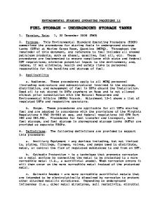
zone equivalent to Zone 4 of the USA. A maximum displacement ductility factor of 2 was used in determining the seismic coefficient for the impulsive mode. Figure 1 shows the seismic coefficients applicable to the impulsive mode of response and the estimated thickness of tank wall, which would be required by each design method for this example tank. The API 650 method is a working stress method, so the coefficient shown in the figure includes a factor of 2.0 for the purposes of comparing it with the NZSEE ultimate limit state approach. For this example, the 1986 NZSEE method gave a significantly larger impulsive mode seismic coefficient and wall thickness requirement than the API 650 method. The proposed NZSEE method, gives a seismic coefficient and wall thickness of a similar order to the API 650 method, but based on a rather more comprehensive approach.
Figure 1: Comparison of Impulsive Mode Coefficients and Required Wall Thickness for a Large Unanchored Steel Tank in Wellington
5. ACKNOWLEDGEMENTS The authors gratefully acknowledge members of the NZSEE Study Group on Seismic Design of Storage Tanks: Dr J. Wood, Phillips & Wood Ltd. Dr G. McVerry, Geological & Nuclear Sciences Dr B. Davidson, University of Auckland Mr J. Mason, Kingston Morrison Ltd Mr R. Jury, Beca Carter Hollings & Ferner Ltd Dr D. Whittaker, Beca Carter Hollings & Ferner Ltd
6. REFERENCES New Zealand National Society for Earthquake Engineering, (1986), Seismic Design of Storage Tanks – Recommendations of a Study Group of the New Zealand National Society for Earthquake Engineering. Standards New Zealand, (1992), NZS 4203:1992, Code of Practice for General Structural Design and Design Loadings for Buildings - Known as the Loadings Code. American Petroleum Institute, (1993 and Addendum 4, 1997), Welded Steel Tanks for Oil Storage. Manos, G. C. and Clough, R. W., (1984), Tank Damage During the May 1983 Coalinga Earthquake, Earthquake Engineering and Structural Dynamics, Vol. 13, 449-466.
4
2376
Table 1: Displacement Ductility Factors Type of Tank
Ductility Factor µ
Steel Tanks on Grade Elastically responding
1.25 21
Unanchored tank designed for uplift (elephants foot shell buckling may occur under seismic overload) Unanchored tank designed for uplift and elastic (diamondshaped) shell buckling mode Anchored with non-ductile holding down bolts
1.25
Anchored with ductile tension yielding holding down bolts
32
Ductile skirt pedestal
32
On concrete base pad designed for rocking
22
1.25
Concrete Tanks on Grade Reinforced Concrete
1.25
Prestressed Concrete
1.0
Tanks of other materials on Grade Timber
1.0
non-ductile materials (eg fibreglass)
1.0
Ductile materials and failure mechanisms
3
Elevated Tanks Notes
as appropriate for support structure 3 1. Check that elastic buckling does not occur before elephants foot 2. Capacity design required to protect against other forms of failure
Table 2: Damping for Horizontal Impulsive Mode Tank Type and Flexibility
Geometry
Concrete Tanks & Stiff Steel Tanks t/R = 0.002
H/R 0.5 1
vs = 1000 m/s 4 4
vs = 500 m/s 13 10
vs = 200 m/s 30 20
2
3
5
14
3
2
3
7
0.5 1
3 3
7 6
20 15
2
2
3
6
3
2
2
3
0.5 1
2 2
4 4
12 9
2
2
3
4
3
2
2
3
Steel Tanks t/R = 0.001
Flexible Steel Tanks t/R = 0.0005
Damping in %
H = Liquid height in tank R = Tank radius T = Tank wall thickness at base vs = Foundation soil shear wave velocity averaged over a depth of 2R beneath the tank base
5
2376
Table 3: Response Modification Factors Accounting for Damping and Ductility Level (with Respect To 5% Damped Elastic Spectrum) Ductility Teq/T1
zetah2
Damping (%)
(%)
0.5
1.0
2.0
5.0
10.0
15.0
20.0
1.0
1.000
0.0
1.75
1.57
1.33
1.00
0.80
0.71
0.67
1.25
1.033
3.5
0.92
0.88
0.83
0.72
0.62
0.58
0.55
1.5
1.063
4.6
0.75
0.72
0.68
0.61
0.54
0.51
0.48
2.0
1.120
5.9
0.58
0.56
0.54
0.48
0.44
0.42
0.40
2.5
1.176
6.9
0.49
0.48
0.46
0.42
0.38
0.36
0.35
3.0
1.230
7.6
0.43
0.43
0.41
0.38
0.35
0.33
0.32
4.0 Notes:
1.337 8.9 0.36 0.36 0.35 0.33 0.30 0.29 0.28 Teq = equivalent linear period. T = initial elastic period Tc = cut-off period at end of plateau at peak of NZS 4203 spectrum (eg 0.45 sec) zetah = equivalent additional viscous damping to represent hysteretic energy dissipation A further factor of Tc/T must be applied if Teq > Tc but initial period T < Tc Table 4: Risk Factors Consequences of Failure
Recommended Design Return Period (yrs)
Risk Factor
Negligible
50
0.5
Slight
200
0.8
Moderate
450
1.0
Serious
1000
1.3
Extreme
2000
1.6
Table 5: Risk Classification Based on Life Safety Risk Hazard level of contents
No. of Persons at Risk of Death or Serious Injury from Tank Failure Low
Moderate
High
0
Negligible
Negligible
Slight
0 < No. < 1
Negligible
Slight
Moderate
1 < No. < 10
Slight
Moderate
Serious
10 < No. < 100
Moderate
Serious
Extreme
No. > 100
Serious
Extreme
Extreme
Table 6: Risk Classification Based on Environmental Factors Environmental
Hazard Posed by Contents
Vulnerability
Low
Moderate
High
Low
Negligible
Slight
Moderate
Moderate
Slight
Moderate
Extreme
High
Moderate Extreme (Environment includes natural environment only)
6
Extreme
2376
Table 7: Risk Classification Based on National or Community Significance Description
Risk Classification
Facilities of no public significance
Negligible
Facilities of secondary public significance
Slight
Facilities of moderate public significance
Moderate
Facilities of high National or community significance which are intended to remain functional after a severe earthquake
Serious
Facilities critical to National Interest which are vital to remain functional after a severe earthquake
Extreme
Table 8: Risk Classification Based on Adjacent Property Value Adjacent Property value at direct risk from Tank Failure (1996 cost index)
Risk Classification
< $100,000
Negligible
< $1,000,000
Slight
< $10,000,000
Moderate
> $10,000,000
Serious
Table 9: Recommended Risk Factors for Non-standard Design Life Design Life (yrs)
Risk Category Negligible
Slight
Moderate
Serious
Extreme