JOIFF GUIDELINE
AUGUST 2015
The International Organisation for Industrial Hazard Management
THE JOIFF STANDARD
GUIDELINE ON
INERTING VERTICAL STORAGE TANKS Nitrogen: a Natural Substance which can Prevent Fires
JOIFF GUIDELINE
AUGUST 2015
This Guideline deals specifically with the use of Nitrogen to inert vertical storage tanks. JOIFF is aware that there are other methods of inerting vertical tanks and this Guideline is in no way intended to negate the use of any alternative method. The use of nitrogen to inert vertical tanks is just one methodology and JOIFF advises that there are other methodologies that should not be discounted.
JOIFF GUIDELINE
AUGUST 2015
CONTENTS 1. Introduction ................................................................................................................. 1 2. Scope .......................................................................................................................... 3 • 2.1 Standards for construction .............................................................................. 3 • 2.2 Operating conditions ....................................................................................... 3 3. Risks of using Nitrogen ............................................................................................... 5 • 3.1 Technical Risks ............................................................................................... 5 • 3.2 Health and safety aspects ............................................................................... 6 • Literature ............................................................................................................... 6 4. Benefits of inerting storage tanks with Nitrogen .......................................................... 8 • 4.1 Introduction ..................................................................................................... 8 • 4.2 Benefits of Inerting Storage Tanks .................................................................. 8 • 4.3 Storage Space ................................................................................................ 8 • 4.4 Max pressure 26 bar (1 bar = 100 kPa) .......................................................... 9 • 4.5 Constant Discharge ......................................................................................... 9 • 4.6 Constant Dynamic Monitoring ......................................................................... 9 • 4.7 Ability to have a Main and Reserve quantity in a Single Tank ........................ 9 • 4.8 Liquid flow reduces pipe size ........................................................................ 10 • 4.9 No requirement for hydrostatic 10 year test .................................................. 10 • 4.10 Cost saving on large system ...................................................................... 10 • 4.11 More robust system integrity ...................................................................... 10 5. Criteria use and implementing Nitrogen Blanketing as a secured Line of Defence .. 11 • 5.1 Standards and codes .................................................................................... 11 • 5.2 Calculations ................................................................................................... 11 • 5.3 Substances Which Cannot Be Inerted .......................................................... 12 • 5.4 Options for Nitrogen Generation ................................................................... 13 • 5.5 Nitrogen Quality ............................................................................................ 14 • 5.6 Measurement of Oxygen of Constant Purge ................................................. 14 • 5.7 Process for Design of Secure Nitrogen Blanketing Storage tanks ................ 15
JOIFF GUIDELINE
AUGUST 2015
6. Venting requirements according to API 2000............................................................ 17 • 6.1 Calculations ................................................................................................... 17 7. Consideration when inerting storage tanks ............................................................... 18 • 7.1 Limiting Oxygen Concentration (LOC) .......................................................... 18 • 7.2 Storage Tank Design .................................................................................... 20 • 7.3 Settings of Pressure Control systems on Tank ............................................. 23 • 7.4 Insulation of Tank .......................................................................................... 24 • 7.5 Purging/inerting Following Opening of Tank ................................................. 24 • 7.6 Inspection testing and maintenance requirements ........................................ 24 8. Flow diagram good practices inerting vertical storage tanks .................................... 26 • 8.1 Flow diagram ................................................................................................. 26 9. Bibliography .............................................................................................................. 27 10. APPENDIX A............................................................................................................. 29 • Onsite Inerting systems ....................................................................................... 29 11. APPENDIX B............................................................................................................. 31 • P&ID Inerting system drawing ............................................................................. 31
Disclaimer: The information in this Guideline and the associated calculations sheets (excel files) are intended to give guidance only. Its contents are not exhaustive nor are they intended to support the views or claims of any persons or Organisations. Neither JOIFF Ltd. nor its Secretariat Fulcrum Consultants nor the Working Group that drew up this Guideline recommend, approve, inspect or certify fire fighting or other equipment, systems or materials, nor do they approve or evaluate testing laboratories or test methods. Neither JOIFF Ltd. nor its Secretariat Fulcrum Consultants nor the Working Group that drew up this Guideline assumes any responsibility for consequences resulting from the use of any information in this Guideline.
===============
Introduction Storage tanks containing flammable liquids with an approved Nitrogen blanket are most unlikely to develop a tank fire. This is recognised in table 22.4.1.1. (a), NFPA 30 (2015): Flammable and Combustible Liquids code, shown below. Table 22.4.1.1(a) Location of aboveground storage tanks storing stable liquids – internal pressure not to exceed a gauge pressure of 2.5 psi (17 kPa) Minimum distance (ft) From property line that is From nearest side of way or can be built upon, public way or from nearest including the opposite site important building on the Type of tank Protection of a public waya same propertya 1 1 Floating roof Protection for exposure /2 diameter of the tank /6 x diameter of the tank None Diameter of tank but need not 1/6 x diameter of the tank exceed 175 ft 1/2 x diameter of the tank 1/6 x diameter of the tank Vertical with weak Approved foam or inerting roof-to-shell seam systemc on tanks not exceeding 150 ft in diameterd 1/3 x diameter of tank Diameter of tank Protection for exposuresb None 2 x diameter of tank but need 1/3 x diameter of tank not exceed 350 ft 1/2 x value in Table Horizontal and vertical tanks Approved inerting systemb on 1/2 x value in Table with emergency relief venting the tank or approved foam 22.4.1.1(b) 22.4.1.1(b) to limit pressures to 2.5 psi system on vertical tanks (gauge pressure of Protection for exposuresb Value in Table 22.4.1.1(b) Value in Table 22.4.1.1(b) 17 kPa) None 2 x value in Table 22.4.1.1(b) Value in Table 22.4.1.1(b) 1/2 x value in Table 1/2 x value in Table Protected aboveground tank None 22.4.1.1(b) 22.4.1.1(b) For SI units, 1 ft = 0.3 m. a The minimum distance cannot be less than 5 ft (1.5 m). b See definition 3.3.46, Protection for Exposures. c See NFPA 69: Standard on Explosion Prevention Systems. d For tanks over 150 ft (45 m) in diameter, use “Protection for Exposures” or “None,” as applicable.
This table states that the inerting system should be “approved”, which means acceptable to the authority having jurisdiction. This Guideline provides relevant information which can support operators to get approval. Inerting of vertical storage tanks has to meet criteria which can differ from the criteria used for inerting process vessels because of the way tanks are constructed and because of the effects of credible incidents. NFPA 30 uses either the presence of fire protection or approved inerting of the ullage space of a storage tank as a factor for the required spacing between tanks and other constructions. The gauge pressure listed is relevant for the behaviour of tanks during incidents. For vertical tanks with weak roof-to-shell seams, additional credit is given for tanks equipped with an inerting system or a foam extinguishing system for tank with a diameter up to 45 m.
According to API 650 (2007): Welded Tanks for Oil Storage, are considered to have a frangible roof (§5.8.5) for emergency venting requirement, if the roof-to-shell joint will fail prior to the shell-tobottom joint in the event of excessive internal pressure. Requirements for the design, construction and the materials used for a frangible roof are described in API 650. A frangible roof is one of the two options for emergency venting provisions of vertical storage tanks with. API 650 (2007) states: Emergency venting requirements are satisfied if the tank is equipped with a weak roof-to-shell attachment (frangible joint) in accordance, with 5.10.2.6, or if the tank is equipped with pressure relief devices meeting the requirements specified in API Std 2000 for emergency venting. Note: Achieving frangible roof on small diameter tanks (e.g. less than 12 m) is impossible. When pressure relief devices are used to satisfy the emergency venting requirements, they shall achieve the flow rates specified in API Std 2000 without exceeding the following limits on internal pressure: a. For unanchored tanks, the pressure relief devices shall be adequate to prevent internal pressure from exceeding the tank design pressure as determined in F.4.1 (subject to the limitations in F.4.2 and F.4.3, as applicable). In calculating limitations per F.4.2, use M = O. b. For anchored tanks, except those designed to F.l.3, the pressure relief devices shall be adequate to prevent internal pressure from exceeding the tank design pressure as determined in F.4.l (subject to the limitations in F.4.3, as applicable). c. For tanks designed to F.l.3 (anchored tanks), the pressure relief devices shall be adequate to prevent internal pressure from exceeding the design pressure specified by the Purchaser.
Scope This guideline relevant to inerting vertical storage tanks with fixed cone or dome roofs with and without an internal floating roof. This guideline does not apply to vertical storage tanks with an external floating roof and tanks with geodesic Aluminium dome roofs.
2.1
Standards for construction
Tanks should be built to the following standards: 1) 2) 3) 4) 5) 6) 7)
API Specification 12: Bolted Tanks for Storage of Production Liquids API Specification 12D: Field Welded Tanks for Storage of Production Liquids API Specification 12F: Shop Welded Tanks for Storage of Production Liquids API Standard 650: Welded Steel Tanks for Oil Storage ANSI/UL 80: Standard for Steel Tanks for Oil-Burner Fuels and Other Combustible Liquids ANSI/UL 142: Standard for Steel Aboveground Tanks for Flammable and Combustible Liquids UL 1316: Standard for Glass-Fiber Reinforced Plastic Underground Storage Tanks for Petroleum Products, Alcohols, and Alcohol-Gasoline Mixtures 8) ANSI/UL 2085: Standard for Protected Aboveground Tanks for Flammable and Combustible Liquids 9) API 620: Design and Construction of Large, Welded, Low-Pressure Storage Tanks 10) EN 14015: Specification for the design and manufacture of site built, vertical, cylindrical, flatbottomed, above ground, welded, steel tanks for the storage of liquids at ambient temperature and above
2.2
Operating conditions
According to Handbook NFPA 30: Flammable and Combustible Liquids code (2012) tanks shall be permitted to operate at pressures from atmospheric to a gauge pressure of 6.9 kPa and shall be limited to a gauge pressure of 17 kPa under emergency venting conditions. The gauge requirement is aimed at preventing the tank to fail as result of a pressure exceeding the 17 kPa. This condition should however interpreted correctly for each tank and in line with the standard used to design the tank. The NFPA Fire Code Handbook (2012: §66.21.4.2.1.4) provides additional information. Vertical tanks are required to be tested only to a pressure that exceeds 1.5 psig (10.3 kPag); however, they are also subject to liquid release upon failure, so the same service restrictions apply. There is an exception: vertical tanks built to UL 142 specifications and labelled “built to weak shell-to-roof joint design” are not expected to fail in such a manner as to release the contents. It is assumed that the weak seam will fail upon overpressure and only vapours will be released. This is important for inerted tanks. Although these tanks are most unlikely to suffer from a tank fire, they can still be exposed to a bund fire which can cause an increase in the internal pressure of the tank due to flame impingement and exposure to radiant heat. Emergency venting conditions are relevant for various conditions for example when a tank is fully exposed to flames from a bund fire, resulting in heating and boiling of its contents. Normal venting is based solely on filling the tank and withdrawal of product from the tank at atmospheric
temperature and pressure changes. Fire exposure can have a substantial effect on the allowable spacing and location of tanks. Flames (and radiant heat) contacting tanks can heat the contained liquid, causing the liquid to boil and can also damage tank supports and the unwetted portion of the tank shell. The increase of pressure due to boiling of the liquid can be mitigated by design or by additional relief valves. For tanks equipped with vents that permit pressures to exceed a gauge pressure of 17 kPa and for low-pressure tanks and pressure vessels, the outlet of all vents and vent drains should be arranged to discharge in a manner that prevents localised overheating of or flame impingement on any part of the tank, if vapours from the vents are ignited. The 17 kPa is based on the experience gained with the incident described below (Handbook NFPA 30: 2012). This requirement was added many years ago as a result of a fire (one of several similar fires) at the Shamrock Oil Company in the Texas panhandle on July 19, 1956. A 2.4 million litre spheroid tank containing about 1.9 million litre of a mixture of pentane [boiling point 36°C] and hexane [boiling point 69°C], with a Reid vapour pressure of 10.2 of 70.3 kPa), was exposed to a liquid ground fire that was being fought by the plant fire brigade with assistance from others. The spheroid tank was designed for 103.4 kPa, in accordance with API 620, Recommended Rules for the Design and Construction of Large, Welded, Low-Pressure Storage Tanks. The contents soon reached its boiling point and the vapours coming from the vent caught fire. The vent had a weather hood that directed the flame down onto the top of the tank. Because the tank was not full, the portion of the shell on which the flame impinged was not cooled by the contents and soon lost strength and failed. The tank ruptured. The resulting fireball killed 19 fire fighters. If vents are equipped with outlet pipes that lack weather hoods, rainwater or condensate can collect and freeze. Thus, open weep holes are provided to drain off water. Flammable vapours emitted from these holes when the vent operates must be able to burn without heating the top of the tank and pressurizing the tank to more than 17.2 kPa. Weep holes are often provided with 90° elbows and small lengths of piping so that any vapours emitted can burn safely without impinging on the tank. Failure of a tank top at a pressure less than 17.2 kPa will be gradual and will not create a hazardous fireball.
Risks of using Nitrogen The health and safety risks of Nitrogen and the risk of the inerting system are discussed in this chapter.
3.1 Technical Risks It should be noted that the scope of this guideline is limited to the use of Nitrogen. Other options for inerting storage tanks are not listed nor are their benefits and disadvantages. For instance some products, such as oxidized bitumen tanks, are best inerted by using steam as it does not promote generation of pyrophorics. A HAZOP study should be performed prior to installing any Nitrogen inerting system. The risk of back-flow of hydrocarbon vapours/liquid in the Nitrogen system should also be considered in this study. Troubleshooting and emergency procedures should be developed and implemented in case of system failure to be prepared for deviation conditions (e.g., what do you do at 3 am during a thunderstorm if your nitrogen supply failed earlier in the day. For the prevention of fires in a storage tank the use of non-contaminated Nitrogen should be guaranteed. The full inerting system shall have a reliability and availability of at least 99% or Safety Integrity Level (SIL) of 2 together with the Layer of Protection Analysis (LOPA). Operators should have two independent forms of Nitrogen supply to or at their site. The most common examples are two different suppliers able to supply Nitrogen to the site by pipeline, or a single supplier, supplying Nitrogen by pipeline from two independent sources, gaseous Nitrogen and liquid Nitrogen that is evaporated and then supplied via the same pipeline. When inerting tanks the credible incident scenarios in the surroundings of the tank should also be considered. Fires around the tank in combination with tank design and spacing. This can result in overpressure in the tank. Overpressure in the tank can also be the result of vents and emergency relief hatches getting blocked due to polymerization of products, freezing, solidification of heated product, wax residues, etc. It should be reviewed if the vent discharge area has to be assessed (using modelling) for health and safety reasons, and/or barricaded with proper signage to prevent inadvertent exposure to oxygen depleted atmosphere. To prevent fires and explosions an ample and secure supply of Nitrogen should always be available for the worst case condition representing the maxim Nitrogen demand. The worst case condition is site specific and can differ based on the provisions for supplying the Nitrogen and the processes requiring the Nitrogen supply. The following two examples are used to illustrate this.
Nitrogen can be supplied by pipeline to a large production site (refinery or chemical plant) by two or three offsite independent sources. Each supply system is designed for delivering the maximum flow required during various process conditions. The storage tanks will be in use during a large turnaround to secure supply of products to their clients. At the start of a turnaround process vessels are intensely flushed with Nitrogen. The amount of
Nitrogen required to purge these vessels exceeds the amount used during process conditions. The required Nitrogen flow for the worst case condition applicable to the storage tank, as described in API 2000 (2014) Venting Atmospheric and Low-pressure Storage Tanks, cannot be guaranteed during a turnaround without additional measures. Therefore the flow of Nitrogen to the process installations has to be restricted during the turnaround by installing an orifice. A tank terminal has a dedicated onsite duplex Nitrogen supply system for inerting specific tanks and products. Each system should be designed to supply the required Nitrogen flow based on the worst case described in API 2000.
3.2 Health and safety aspects The use of Nitrogen brings health and safety risks. Users of this guideline are advised study these risks in detail. A non-exhaustive literature list is provided in paragraph 3.3 below. Nitrogen has the following properties: It is colourless It is odourless It is an asphyxiant. Breathing Nitrogen can quickly kill a person. Because of this property the bund/dike itself may require a confined space entry procedure. This depends on the height of the bund wall and the distance between the tanks and the bund wall. This aspect is also relevant for double wall tanks. A rigorous lock-out/tag-out for tank entry/maintenance should be established and implemented for inerted storage tanks. It will fool readings from catalytic explosion meters which require oxygen to work properly: Instrument and Operations technicians will require specific training. Inerting of specific products, like some fuel-oils, bitumen, will result in the development of dry pyrophorics which will self-ignite when oxygen is allowed back in the tank (e.g., for maintenance).
Literature The literature which specifically applicable to this chapter is listed in this paragraph, but also in the bibliography of this document. American National Standard Institute (ANSI) / American Society of Safety Engineers (ASSE), 2003. Safety Requirements for Confined Spaces, ANSI/ASSE Z117.1-2003 American Petroleum Institute (API) Publication 2217A (07/01/2009): Guidelines for Work in Inert Confined Spaces in the Petroleum Industry US Occupational Safety & Health Administration Standard Permit-Required Confined Spaces, 29 CFR 1910.146 UK Health and Safety Executive: - Safe work in confined spaces leaflet INDG258. http://www.hse.gov.uk/pubns/indg258.pdf - Safe work in confined spaces. Confined Spaces Regulations 1997, ISBN 978 0 71766 233 3 - Cleaning and gas freeing of tanks containing flammable residues 1985, ISBN 0 71761 365 8 US Chemical Safety Board: - Union Carbide Corp. Nitrogen Asphyxiation Incident Hahnville, LA, March 27, 1998; Report No. 98-05-I-LA - Valero Refinery Asphyxiation Incident Delaware City, DE, November 5, 2005; case study No. 2006-02-I-DE and video animation on CSB website - Safety Bulletin: Hazards of Nitrogen Asphyxiation, No. 2003-10-B, June 2003 US Compressed Gas Association, Inc.: - Safety Bulletin, Oxygen-Deficient Atmospheres, SB-2, 2007 - Safety Alert, Hazards of Nitrogen/Inert gas creating an oxygen-deficient atmosphere, SA-17, 2008 BP - ICHEME Process Safety booklets:
Control of Work (2007 ed), ISBN 978 0 85295 514 7 Confined Space Entry (2005 ed), ISBN 978 0 85295 479 4 e - Hazards of Nitrogen and Catalyst Handling (2011, 6 ed) electronic Isbn978-1-61583-499-0 http://app.knovel.com/web/toc.v/cid:kpBPPSSHN1/viewerType:toc/root_slug:bp-processsafety-series-6 -
Benefits of inerting storage tanks with Nitrogen 4.1
Introduction
Nitrogen is an inert gas that can be used for the purposes of extinguishing and inerting. Extinguishing systems based on inert gases often are stored in high pressure cylinders and require a great number of cylinders to provided extinguishing at design concentration. Nitrogen is one of four types of gas used, the others being: Argon; Argon/Nitrogen mix; and Argon/Aitrogen and Carbon dioxide mix.
4.2
Benefits of Inerting Storage Tanks
The major benefit for the use of inerting a storage tank is that fires are prevented in the tank, so no fire damage can occur and depending on the reliability and availability of the inerting system it can be considered not to fit fire fighting systems for inerted tanks. The benefits of using Nitrogen for inerting storage tanks can be summarized as follows:
Low storage space Max pressure 26 bar Constant discharge Constant dynamic monitoring Ability to have a main and reserve quantity in a single tank As Nitrogen is delivered and stored as a liquid the pipe size is reduced Requirement for hydrostatic 10 year testing is not a requirement in many countries Cost saving on large system More robust system integrity
More details of the benefits of using Nitrogen are set out throughout this Guideline.
4.3
Storage Space
At room temperature inert gases cannot be liquefied and the only method of decreasing storage footprint is to compress the gas and/or use larger cylinders. The practicalities of pressure regulations and current technology limit cylinder size to 140 litres and pressures to 300 bar (at 15oC, which is the reference pressure in the ISO/BS/EN standards). By liquefying the Nitrogen the volume of storage can be reduced relative to cylinder systems. An illustrative example of storage space required is given for the use of cylinder systems (based on 80 litre, 300 bar, design concentration BS EN 15004 high hazard 45.2%) is when compared with liquid tank equivalent:
Table: Efficient use of space using liquid Nitrogen Volume m3
Number of Nitrogen Cylinders
1,000
29
5,000
141
10,000
282
15,000
423
20,000
564
Footprint m x m = m2 (volume m3)
Equivalent Liquid Tank Storage Volume 3 m
3.6 x 0.997 = 3.59 (7.2) 16.55 x 0.997= 16.5 (33.1) 33.00 x 0.997 = 32.9 (66) 49.45 x 0.997 = 49.3 (98.9) 65.90 x 0.997 = 65,7 (131.8)
1.6 7.8 15.5 23.2 30.9
The use of cylinders is suitable for small tanks. Lager tanks require larger supply sources, which are addressed in the next chapter.
4.4
Max pressure 26 bar (1 bar = 100 kPa)
Storage of high pressure cylinders impacts on installation, maintenance and operation. There have been several reported incidents of personnel being injured or killed and property being damaged as a result of high pressure cylinders discharging through handling errors at installation. A 300 bar (30,000 kPa) cylinder is a projectile that can be inadvertently discharged. Incidents are recorded of incorrect pipe installation or changes in the system over its lifetime, which has resulted in damage, when discharged. With a liquid Nitrogen storage system, the maximum pressure is 26 bar, considerably reducing the risk of an over-pressure incident.
4.5
Constant Discharge
Cylinder systems containing liquid Nitrogen can discharge constantly at 60 or 80 bars with large pipe work, or at 300 bars with smaller pipe work and fitted with an orifice plate that reduces pressure to 60 bars. A Nitrogen tank system can maintain a constant discharge at 20 bars on a constant pipe diameter and without the requirement of restrictors (orifice plates). The liquid Nitrogen system requires a vaporizer to bring the liquid Nitrogen into its gaseous state at ambient temperature to avoid brittle fracture of steel pipes and tanks.
4.6
Constant Dynamic Monitoring
A cylinder system can only monitor via a pressure gauge per cylinder with a crude on-off fault switch indicating low pressure (contents) on a particular cylinder. On an inerting tank system the liquid level can be dynamically monitored continuously via a 4 – 20 mA linear output.
4.7
Ability to have a Main and Reserve quantity in a Single Tank
Many systems require sufficient extinguishing or inerting Nitrogen for a reserve actuation, so that no business interruption can occur. Cylinder systems are required to be uninstalled, transported to a gas refilling station, and then reinstalled. This can be very time consuming and expensive (the gas is cheap but the labour and transport can be considerable).
A Nitrogen storage tank can easily be increased in size to hold sufficient gas for a main and reserve discharge. In this case, Refilling is simply an exercise of a vehicle driving to site, and topping up there, saving considerable cost in labour and transport over a cylinder based system.
4.8
Liquid flow reduces pipe size
With discharging Nitrogen in liquid form, it is possible to reduce pipe sizes for the equivalent amount of Nitrogen discharged in a gaseous state. The liquid Nitrogen system requires a vaporizer to bring the liquid Nitrogen into its gaseous state at ambient temperature to avoid brittle fracture of steel pipes and tanks.
4.9
No requirement for hydrostatic 10 year test
Cylinder systems require a 10 year hydrostatic test. A hydrostatic test requires actual removal of the cylinders, normally by service replacement, every 10 years. This is expensive in labour and transport and disruptive.
4.10 Cost saving on large system
For volumes to be protected over 5,000m3, then the installation of a Nitrogen tank storage system with sufficient gas for main and reserve discharge becomes progressively more economical. Maintenance and on-going running costs also progressively decrease with system size.
4.11 More robust system integrity Cylinder based systems rely fundamentally on integrity of connecting actuation lines, and configuration, particularly for multi-area risks, can be extremely complicated. Several low pressure cylinders could compromise system integrity but a tank system always needs full monitoring to warn of any potentially dangerous low level.
Criteria use and implementing Nitrogen Blanketing as a secured Line of Defence Specific criteria have to be met before Nitrogen blanketing can qualify as a secure Line of Defense for preventing a fire. These criteria are discussed is this chapter.
5.1
Standards and codes
The latest version of the following standards and codes should be applied when using Nitrogen blanketing of vertical storage tanks:
NFPA 30: Flammable and Combustible Liquids Code NFPA 69: Standard on Explosion Prevention Systems FM Data Sheet 7-59: INERTING AND PURGING OF TANKS, PROCESS VESSELS, AND EQUIPMENT FM Data Sheet 7-88: FLAMMABLE LIQUID STORAGE TANKS API STANDARD 2000: Venting Atmospheric and Low-pressure Storage Tanks
5.2
Calculations
5.2.1 Limiting Oxygen Concentration NFPA 69 and FM Data Sheet 7-59 provide lists with their Limiting Oxygen Concentrations (LOC). The LOC will be discussed in more detail in chapter 7. If no LOC is provided for a certain substance, it can be calculated using a conservative method using the Lower Flammability Level (LFL) of the substance and the moles of oxygen required for stoichiometric burning of the substance. LFL x moles required for stoichiometric burning = LOC in Vol% Example using Benzene: LFL of Benzene is 1.35 % C6H6 + 7½ O2 6 CO2 + 3 H2O 7½ x 1.35 = 9.45 Vol% while NFPA lists 10.1 Vol%.
5.2.2 Storage at Elevated Temperatures Products stored at elevated temperatures may require a lower oxygen level to establish an inert atmosphere, de pending on the temperature. Therefore the suitability of values listed in references below should first be reviewed: - NFPA 69 (2015) Standard on Explosion Prevention Systems, Table C.1(a) Limiting Oxidant Concentrations for Flammable Gases When Nitrogen or Carbon Dioxide Are Used as Diluents - FM datasheet 7-58 (2000) Inerting and purging of tanks, process vessels, and equipment, Table 1. Maximum Recommended Percentage of Oxygen to Prevent Ignition of Flammable Gases and Vapors Using Nitrogen and Carbon Dioxide for Inerting
The LOC of a product is affected by the storage temperature. The LOC for elevated temperatures can be calculated using the following calculation which is incorporated in NFPA 69. LOC@ t = LOC Vol % @ 20°C X (1-0.0014(t-20))x 293/(273+t) Where “t” is storage temperature in °C. It is also possible to apply the equation of Zabetakis (below) to estimate the temperature effects on the lower flammability limit in combination with the calculation under 5.2.1. LFLT = LFL25 x [(1 - (0.75/ Hc) X (T- 25)] 1 T = elevated temperature Hc = heat of combustion (kcal/mol)
5.2.3 Effect of pressure A change in pressure affects the LFL and Upper Flammability Level (UFL). As pressure increases the LFL is decreased and the UFL is increased. While an increase in pressure has only a slight effect on the LFL, it increases the UFL significantly. A decrease in pressure below one atmosphere has little effect on the LFL until the low pressure limit, generally around 5 kPa, below which the mixture becomes non-flammable.
5.2.4 Hydrocarbon mixtures When mixtures of hydrocarbon are present the limits of flammability of the mixture can be determined using Le Chatelier's rule1. But do not use this method for azeotropic mixtures as they do not follow Raoult's law. The equation below works well for some flammable mixtures and not for others. This equation may not work well for chemically dissimilar materials. This equation should therefore be applied with discretion. Taking the above into consideration the LFL can be calculated using the following equation2
= “i” and “mix” refer to hydrocarbon component and the hydrocarbon mixture “Yi” [% v/v] is the concentration of the hydrocarbon component in the mixture excluding oxygen and inert gas components like Nitrogen. “N” is the number of hydrocarbon liquids in the mixture.
5.3
Substances Which Cannot Be Inerted
Before inerting is applied, it must be established if inerting can be effective for a specific substance and its storage conditions.
1
Conditions affecting flammability limits (http://www.chilworth.com/wp-content/uploads/2012/10/SW20004ConditionsAffectingFlammabilityLimits.pdf) 2
Conditions affecting flammability limits (http://www.chilworth.com/wp-content/uploads/2012/10/SW20004ConditionsAffectingFlammabilityLimits.pdf)
First of all the substance flammability range is important. For example Ethylene Oxide cannot be inerted because of its flammability range in air which lies between 3 % (Vol) Oxygen and 100 % (Vol) via decomposition. Organic peroxides like TBHP (tert-Butyl hydroperoxide) cannot be inerted either. The peroxide can generate reactive Oxygen molecules. Adding a constant supply of Nitrogen to a storage tank with TBHP will significantly lower the risk of a fire but the tank cannot be considered to be inert. Many monomers which can polymerise cannot be inerted either. A polymerisation inhibitor which requires oxygen to stay active (See FM Data Sheet 7-59) is added to the substance which cannot be effective if inerting with Nitrogen is used. Do not use inerting in tanks with monomers containing inhibitors that require oxygen to maintain activity. Examples of inhibitors are: hydroquinone and methyl ether of hydroquinone.
5.4
Options for Nitrogen Generation
The supply of Nitrogen should be secure under all conditions and should be able to supply the required amount of Nitrogen for the worst case scenario. The worst case scenario should be determined for this purpose. API 2000 provides information on this, but the suggested scenario may not suffice when the tank terminal is part of a large petrochemical production site. For such location the Nitrogen required for purging process vessels during a turnaround may produce the worst case scenario. Nitrogen can be generated on site from a liquid storage vessel. The operator should have at least two independent systems where liquid Nitrogen is stored and evaporated. When Nitrogen is supplied by a third party by pipeline it is usually delivered to the site in gaseous form. Again two fully independent supply sources should be available. Nitrogen with a purity of >99% can be generated/supplied on site using various technologies:
Pressure Swing Adsorption Membrane Technology Cryogenic Separation Evaporation of Liquid Storage (liquid from Third party) Bottled or piped Nitrogen gas supply from Third party
5.4.1 Pressure Swing Adsorption The characteristic of molecular sieve crystals (normally Carbon Molecular Sieve) to differentially adsorb the gases comprising air make a high Nitrogen concentration possible in devices of smallscale and modest power consumption. Once the adsorbent has reached its maximum saturation capacity, the cylinder goes through a depressurisation cycle resulting in near-vacuum conditions inside the cylinder. This results in the by-product gas molecules separating from the adsorbent so they can be flushed from the cylinder making it ready for further use. During the depressurisation cycle the cylinder cannot be used for Nitrogen generation. To ensure the highest purity of Nitrogen (up to 99.9995% Nitrogen purity can be achieved with Pressure Swing Adsorption – PSA - Nitrogen generators) and enable continuous, uninterrupted
Nitrogen production, Pressure Swing Adsorption technology uses two identical Carbon Molecular Sieve columns which are alternately pressurized with compressed air. With this process, Nitrogen is produced by the plant at the above-atmospheric pressure, while the adsorbent regeneration is accomplished at below-atmospheric pressure.
5.4.2 Membrane Technology A polymeric hollow fibre selectively permeates oxygen, water vapour, and other impurities out of its side walls while allowing Nitrogen to flow through its centre and emerge as product. Compared to the other technologies Membrane technology supplies lower purity Nitrogen at higher flow rates, however, purity above 99% can still be achieved.
5.4.3 Cryogenic Separation The concept of Nitrogen separation by cryogenic systems is based on the different evaporation temperatures of the several components in the air. Depending on the supplier, the system is made up of the steps and equipment described below. Atmospheric air is compressed and cooled. The moisture is separated from the air before the air is purified in alternatively operating molecular sieves, removing water, carbon dioxide, hydrocarbons, etc. The purified air enters a “cold box” and is cooled down in a counter-current heat exchanger by the cold separation products to almost the liquefaction temperature of oxygen (at that pressure). The air enters the distillation column which separates the air mixture into high quality Nitrogen gas (top of the column) and oxygen enriched liquid. The required refrigeration for the cold box can be achieved through an expander or through an external liquid Nitrogen supply. Purities with only 1 – 100 ppm oxygen can be achieved. Depending on the required purity and capacity one of the technologies can be chosen in close cooperation with the engineering company or Vendors.
5.5
Nitrogen Quality
The Nitrogen purity should be over 99 %. Using a higher purity makes it possible to reduce the number of volume replacements needed.
5.6
Measurement of Oxygen of Constant Purge
When designing a secure inerting system for a vertical storage tank the operator has the choice to supply the Nitrogen based on oxygen measurement or based on calculation in combination with a valve operated by the pressure in the tank. Some disadvantages of Oxygen meters include: Oxygen meters are known to be subject to malfunction. Oxygen meters have to be placed at several locations in the tank for the measurement to be representative because the Oxygen concentration is the ullage space of the tank.
An Oxygen meter generates an alarm when passing through a pre-set value. It is unknown what the actual Oxygen concentration is after the alarm was raised, it can be much higher than when the alarm was raised and when checked, can already have reached a level at which a flammable vapour mixture is present in the tank.
Therefore the permanent flow which was designed on calculations listed in API 2000 provides a more reliable blanketing than blanketing using Oxygen meters.
5.7
Process for Design of Secure Nitrogen Blanketing Storage tanks
If all the options for inerting the vapour space of a storage tanks have been reviewed and the decision has been made to use Nitrogen blanketing, the system to accomplish this has to be designed. Designing the system for secure Nitrogen blanketing can however be a very complex process with many variables. Overlooking one or more variable can result in a system which does not provide an inert atmosphere in the ullage space of the tank under all conditions. It therefore recommended to use a Performance Based (PFB) approach as shown on the flow diagram on the next page. Meticulously going through these 12 steps using the relevant standards and correct process conditions can result in a tailor made inerting of the site’s storage tanks. The scope of this Guideline does not include detailed information for using the performance based flow diagram below. The SFPE Engineering Guide to Performance-Based Fire Protection is a good reference about using the PFB-process. Step 3 of the process “Identify “N2-consumers” & Design Objectives” can be used in combination with a “What if” decisions to find the best solutions for designing the required maximum Nitrogen flow. API 2000 has defined a worst case situation for storage tanks with a low liquid level. But if this is never the case in practice and a higher level in the tanks is secured under all conditions than the PFB approach allows the system to be designed for that condition. A second publication is the SFPE Code Official’s Guide to Performance-Based Design Review. This book provides good guidance on how to review the PFB design. Not only does using a PFB approach help every stakeholder find the solutions that best fits their process it also helps to create a level playing field.
Flow diagram for Performance Based design of secure Nitrogen Blanketing of storage tanks
Venting requirements according to API 2000 6.1 Calculations
Calculations for venting requirements according API 2000, 7th edition (2014) can only be carried out in elaborate calculations. The calculation tool that accompanies this Guideline can be downloaded from the JOIFF website under the downloads button (http://joiff.com/inerting-vertical-tanks/). This "tool" is provided as part of the Guideline and should not be used by competent persons who can show that were trained to interpret the requirements of API 2000 and have the experience to identify conditions relevant for making these calculation. Usage of the tool requires a password.
Consideration when inerting storage tanks 7.1
Limiting Oxygen Concentration (LOC)
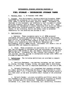
The limiting oxygen concentration (LOC)is defined as the limiting concentration of oxygen below which combustion is not possible, independent of the concentration of fuel. It is expressed in units of volume percent of oxygen. The LOC varies with pressure and temperature. It is also dependent on the type of inert (non-flammable) gas being used. The limiting of the concentration of oxidant in a fuel-oxidant-diluent mixture, below which an ignition and/or subsequent deflagration cannot occur, under specified conditions, may be achieved by maintaining an atmosphere that is inert in the vapour space of a container or vessel. The addition of an inert diluent to a mixture of combustible material and oxidant affects the lower and upper flammable limits and the limiting oxidant concentration. The figure below shows a typical flammability diagram that represents a mixture of a combustible gas; an inert gas, Nitrogen; and an oxidant, oxygen at a given temperature and pressure. A mixture of air (79 percent N2 and 21 percent O2 by volume) and combustible gas is represented by the line formed by points DABE. A given mixture of the combustible gas and air, whether ignitable or not, is specified by a point on this line. Point A indicates the upper flammable limit of this mixture, and point B represents its lower flammable limit. Any point within the area bounded by FBCAGF is in the flammable range and can be ignited. Any point outside this area represents a mixture that cannot be ignited. Point C represents the limiting oxidant concentration to prevent ignition; any mixture containing less oxygen cannot be ignited.
Figure: flammability diagram a mixture of a combustible gas at a given temperature and pressure3
Any mixture of oxygen and combustible gas alone is represented by the left side of the triangle. Any mixture of Nitrogen and combustible gas alone is represented by the right side of the triangle.
7.1.1 System Requirements to Ensure Effective LOC 1) Instrumentation should be installed in as many points as necessary to ensure the desired oxidant concentration reduction within the protected system. 2) The determination of the LOC for the system should be based on the worst credible case gas mixture yielding the smallest LOC. 3) A safety margin should be maintained between the LOC and the normal working concentration in the system. 4) The safety margin should take into account all of the following factors: a. Fluctuations occurring in the system b. Sensitivity and reliability of monitoring and control equipment c. Probability and consequences of an explosion
3
Image from Appendix A, NFPA 69 (2008): Standard on Explosion Prevention Systems
5) Where the oxygen concentration is not continuously monitored and controlled with safety interlocks, one of the following requirements should be met: a. Where the LOC is greater than or equal to 7.5 percent, a safety margin of at least 4.5 volume percent below the worst credible case LOC should be maintained. b. Where the LOC is less than 7.5 percent, the oxygen concentration should be designed to operate at no more than 40 percent of the LOC. 6) The vapour space in low-pressure field storage tanks that have padding should not require checking of the oxygen concentration
7.2
Storage Tank Design
All atmospheric pressure vertical storage tanks should be considered as confined spaces, but this does not mean that all vertical storage tank designs can be inerted with Nitrogen. The following storage tanks types can fitted with provision to prohibit direct contact with the surrounding atmosphere during ‘normal’ operations: a. Carbon/stainless steel cone/dome roof tanks. In these tanks the vapour of the product in the tank is in direct contact with the liquid in the tank. b. Carbon/stainless steel cone/dome roof tanks with internal carbon steel floating roof fitted with pontoons which is also known as inner floater (IFR). The floating roof floats on the liquid in the tank. There is a space filled with vapour below the floating roof because it floats on pontoons. The floating roof can be fitted with a single or double seal. c. Carbon/stainless steel cone/dome roof tanks with internal full contact Aluminum floating roof which is commonly fitted with double seals. There is no vapour space below the floating roof as the roof is in direct contact with the liquid in the tank. d. Carbon/stainless steel cone/dome roof tanks with internal full contact GRE floating roof which is commonly fitted with double seals. There is no vapour space below the floating roof. e. Carbons steel tanks with non-ventilated Aluminium felted4 geodesic roof. f. Carbon steel tanks with non-ventilated Aluminium felted4 geodesic roof and carbon steel inner floater on pontoons with single or double seals. g. Carbon steel tanks with non-ventilated Aluminium felted4 geodesic roof and full contact Aluminium inner floater. h. Carbon steel tanks with non-ventilated Aluminium felted4 geodesic roof and full contact GRE inner floater. Images of various tank designs are shown below.
4
Felted roofs are covered with a composite. Is the roof has been fitted in a way that tightness and strength of the roof provides the same properties as present with carbon steel cone/dome roofs, the space above the floating roof can potentially be inerted. At the time of this guideline was written no known standards that specifically addresses these types of tanks. Therefore no specific code could be listed in chapter 2.
Aerial photo cone roof storage tanks
Aluminium dome roof tank
Storage tanks with carbon steel dome roof
Storage tank with felted dome roof
7.2.1 Vapour The composition of the vapour space in storage tanks without a floating roof is in equilibrium with the liquid in the tank. If the liquid that is being stored in the tank is a mixture of hydrocarbons the component with the lowest boiling point commonly is present in the highest concentration in the vapour space. Liquids that form an azeotropic or hetero-azeotropic boiling point behave in a different way. An azeotrope is a mixture of two or more liquids in such a ratio that its composition cannot be changed by simple distillation. This occurs because, when an azeotrope is boiled, the resulting vapour has the same ratio of constituents as the original mixture. A hetero-azeotrope is a more intricate form of an azeotrope as the vapour phase coexists with two liquid phases. In storage tanks that are fitted with an innerfloater the vapour concentration is much lower as the floating roof prevents direct contact with the ullage space and the liquid. The amount of vapour depends on the design of the floating roof. Floating roofs with two seals have lower vapour concentrations in the ullage space. Full contact floating roofs also have less vapour in the ullage space. A general impression in of the influence of the design of the innerfloater has on the release of the vapour is shown.
5
Comparison of vapour release from a tank without and with innerfloater
Floating roof design and associated vapour release6
Various designs of the seals of the floating roofs are shown below.
7
Single Foam Seal
5 6
Primary shoe seal
8
Slide 43 Storage tank basic training (rev 2). http://www.slideshare.net/ledzung/storage-tanks-basic-training-rev-2 Slide 45 Storage tank basic training (rev 2). http://www.slideshare.net/ledzung/storage-tanks-basic-training-rev-2
7
http://www.easyfairs.com/uploads/tx_ef/IFR-1-.pdf (accessed: 02-12-2013)
8
http://www.bbbtankservices.com/tank_seals.htm (accessed: o2-12-2013)
Double seal9
7.3
Double Seal System for Floating Roofs Using 10 Plastic-Foam Log (Secondary Seal)
Settings of Pressure Control systems on Tank
Setting of PVV, Emergency venting, connection to vapour treatment system and other instrumentation requirements are discussed in this paragraph.
7.3.1 Tank Breathing Venting control is required on an inerted storage tank to deal with normal breathing of the tank due to ambient conditions, or pressure variations due to filling or emptying of the tank. Thus vents should be designed for normal pressure and vacuum relief. The settings of the devices should be below the relief set point. Correctly sized Pressure vacuum valves may be installed to allow the tank to breathe without damage. Breathing vents should be located on top of the tank and directed to a vapour abatement system in order to minimize atmospheric emissions and reduce risk of local ignition of flammable vapours. Releases to the environment are subject to environmental protection laws and local requirements. In some cases flame arrestors may be required on the vents to prevent spread of fire. Where installed, the flame arrestors should be designed in such a way as to allow inspection for product build-up, fouling and blockage.
7.3.2 Emergency Relief In addition there is a requirement to allow for emergency relief in case of fire engulfment leading to excessive pressure. This should be designed according to appropriate codes or standards such as API 521 or API 2000 as appropriate. Ensure that consideration is given to requirements with respect to the height of vents above the tank or ground level. The relief set point should be at or below the Maximum Allowable Working Pressure of the tank.
7.3.3 Instrumentation All tanks should have a suitable method of indicating level. A high level switch, separate to the tank level indicator, is required to prevent overfilling. 9
http://www.emexco.nl/PDF/PT-D1.pdf (accessed 02-12-2013)
10
NFPA 11 (2010) Standard for Low-, Medium-, and High-Expansion Foam
Other instrumentation may be required depending on tank requirements, for example, temperature instruments will be required if the tank is heated or cooled. Tank components should be assessed to ensure that they are constructed of a material compatible with the chemical and physical properties of the contents of the tank and surrounding environment. All instrumentation should be clearly identified with weatherproof securely attached tags.
7.4
Insulation of Tank
The temperature in insulated tanks does not vary much under the influence of changes in the atmosphere. As a result the inbreathing and venting caused by changes in atmospheric temperatures is much lower than with non-insulated tanks. 7.5 Heated storage Products which are being stored at elevated temperatures require a lower oxygen level than listed in tables Table C.1(a) Limiting Oxidant Concentrations for Flammable Gases When Nitrogen or Carbon Dioxide Are Used as Diluents in NFPA 69 and Table 1. Maximum Recommended Percentage of Oxygen to Prevent Ignition of Flammable Gases and Vapors Using Nitrogen and Carbon Dioxide for Inerting in FM data sheet 7-59.
7.5
Purging/inerting Following Opening of Tank
When opening a tank the atmosphere within the tank should make the transition from the original inert condition back to the inert condition without passing through the flammable condition; in practice, this means that, before any tank is opened, it should be purged with inert gas until the hydrocarbon content of the tank atmosphere is below the critical dilution line and kept at a positive pressure during the opening of the tank. This may be referred to as continuous purging whilst the tank is open
7.5.1 Methods of Inert gas replacement Two operations involve replacement of inert gas in tanks, namely: (a) Dilution, which is a mixing process; (b) displacement, which is a layering process. In each of these replacement operations, one of two processes can predominate. These two processes have a marked effect on the method of monitoring the tank atmosphere and the interpretation of the results The dilution theory assumes that the incoming inert gas mixes with the original gases/vapours to form a homogeneous mixture throughout the tank vapour space; the result is that the concentration of the original gas/vapour decreases exponentially. In practice, the actual rate of gas/vapour replacement depends upon the volume flow of the incoming inert gas, its entry velocity and the dimensions of the tank vapour space. For complete gas/vapour displacement, it is important that the entry velocity of the incoming inert gas be high enough for the jet to reach the full vapour space; it is therefore important to confirm the ability of every installation using this principle to achieve the required degree of gas replacement throughout the tank vapour space.
7.6
Inspection testing and maintenance requirements
As most tanks that are fitted with a secure Nitrogen inerting system have no fire protection system this system requires an availability and reliability of ≥98 %. If the system is not reliable and/or available a fire can occur. Such a fire can often not be extinguished using mobile firefighting equipment as the fire cannot be addressed. The tank has an emergency venting hatch which means the roof will stay on top of the cylinder. It is very difficult if not impossible to fight this fire through this hatch.
Therefore a performance based Inspection Testing and Maintenance program which is implemented in the site’s Safety Management System should be in place to secure the required availability and reliability of the inerting system.
7.6.1 Storage Tank The storage tank and associated fittings, surrounding bunds, etc. should be maintained in a safe condition by suitably qualified and trained personnel. A review should be undertaken during tank installation design to ensure that adequate access is allowed for all maintenance tasks to be undertaken safely. This may also include requirements for handrails, barriers, ladders, etc. The storage tank and all components should be assessed at time of installation to allow preparation of an appropriate preventative maintenance schedule. If the components are subject to corrosion then the preventative maintenance program should include inspection and testing at a frequency appropriate to detect or predict potential failures. For floating roof tanks, buoyancy should be checked as well as bonding and obstruction of tank connections. Inspections should also be undertaken to check for damage to the rim seal and the drainage system if installed. Visual inspections of the tank externals and areas around the tank should be inspected on a regular basis to promptly detect any leakage. This inspection should include, as a minimum, wall thickness checks, nozzle connections and tank supports. Areas inside the vessel cladding and insulation (if installed) should also be periodically checked. A manway should be provided on the tank to allow internal access for examination and cleaning as required.
7.6.2 Instrumentation and Fittings If flame arrestors are installed then regular attention should be paid to check that they are not blocked. Vent pipes and any installed filters should also be regularly checked for blockage or liquid hold-up. Breather valves, regulators, etc., should be checked for corrosion and to ensure that they are adhering to set points. Regular calibration of all instruments should be included in the Preventative Maintenance program.
7.6.3 General All preventative maintenance tasks should be recorded and the maintenance history retained. Frequency and scope of inspection should be based on manufacturer’s guidelines or local legal requirements. Fire protection devices, bunds, handrails, etc., should also be inspected regularly.
Flow diagram good practices inerting vertical storage tanks The flow diagram below is a quick guide for the good practices described in the chapter 1 - 7 in this Guideline. It must be established first that the storage tank is suitable for inerting with Nitrogen.
8.1
Flow diagram
Bibliography
American National Standard Institute (ANSI) / American Society of Safety Engineers (ASSE), 2003. Safety Requirements for Confined Spaces, ANSI/ASSE Z117.1-2003 ANSI/UL 80: Standard for Steel Tanks for Oil-Burner Fuels and Other Combustible Liquids ANSI/UL 142: Standard for Steel Aboveground Tanks for Flammable and Combustible Liquids ANSI/UL 2085: Standard for Protected Aboveground Tanks for Flammable and Combustible Liquids API 650 (2007): Welded Tanks for Oil Storage API Specification 12: Bolted Tanks for Storage of Production Liquids API Specification 12D: Field Welded Tanks for Storage of Production Liquids API Specification 12F: Shop Welded Tanks for Storage of Production Liquids API 620: Design and Construction of Large, Welded, Low-Pressure Storage Tanks API 2000 (2014 7th ed.) Venting Atmospheric and Low-pressure Storage Tanks API 2217A (07/01/2009): Guidelines for Work in Inert Confined Spaces in the Petroleum Industry BP - ICHEME Process Safety booklets: - Control of Work (2007 ed), ISBN 978 0 85295 514 7 - Confined Space Entry (2005 ed), ISBN 978 0 85295 479 4 e - Hazards of Nitrogen and Catalyst Handling (2011, 6 ed) electronic Isbn978-1-61583-499-0 http://app.knovel.com/web/toc.v/cid:kpBPPSSHN1/viewerType:toc/root_slug:bp-processsafety-series-6 BS EN 15004-1 Fixed firefighting systems. Gas extinguishing systems. Design, installation and maintenance Conditions affecting flammability limits (http://www.chilworth.com/wpcontent/uploads/2012/10/SW2000-4ConditionsAffectingFlammabilityLimits.pdf) EN 14015: Specification for the design and manufacture of site built, vertical, cylindrical, flatbottomed, above ground, welded, steel tanks for the storage of liquids at ambient temperature and above FM Data Sheet 7-59: INERTING AND PURGING OF TANKS, PROCESS VESSELS, AND EQUIPMENT FM Data Sheet 7-88: FLAMMABLE LIQUID STORAGE TANKS NFPA 11 (2010) Standard for Low-, Medium-, and High-Expansion Foam NFPA 30 (2015): Flammable and Combustible Liquids code NFPA Fire Code Handbook (2012) NFPA 69: Standard on Explosion Prevention Systems SFPE Engineering Guide to Performance-Based Fire Protection SFPE Code Official’s Guide to Performance-Based Design Review UK Health and Safety Executive: - Safe work in confined spaces leaflet INDG258. http://www.hse.gov.uk/pubns/indg258.pdf - Safe work in confined spaces. Confined Spaces Regulations 1997, ISBN 978 0 71766 233 3 - Cleaning and gas freeing of tanks containing flammable residues 1985, ISBN 0 71761 365 8 UL 1316: Standard for Glass-Fiber Reinforced Plastic Underground Storage Tanks for Petroleum Products, Alcohols, and Alcohol-Gasoline Mixtures US Chemical Safety Board:
Union Carbide Corp. Nitrogen Asphyxiation Incident Hahnville, LA, March 27, 1998; Report No. 98-05-I-LA - Valero Refinery Asphyxiation Incident Delaware City, DE, November 5, 2005; case study No. 2006-02-I-DE and video animation on CSB website - Safety Bulletin: Hazards of Nitrogen Asphyxiation, No. 2003-10-B, June 2003 US Compressed Gas Association, Inc.: - Safety Bulletin, Oxygen-Deficient Atmospheres, SB-2, 2007 - Safety Alert, Hazards of Nitrogen/Inert gas creating an oxygen-deficient atmosphere, SA-17, 2008 US Occupational Safety & Health Administration Standard Permit-Required Confined Spaces, 29 CFR 1910.146 -
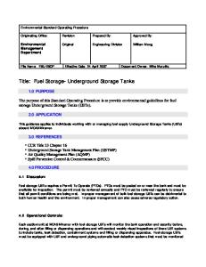
APPENDIX A Onsite Inerting systems Nitrogen can be supplied by pipeline. This is often the case at larger industrial sites. Smaller sites often have a Nitrogen storage tanks with vaporizers. Examples of these systems are shown below. The photos of the systems below can be used for nitrogen blanketing but also for fire extinguishing installations
Horizontal Nitrogen tanks with liquid vaporizers
Horizontal Nitrogen tanks with liquid vaporizer
Drawing of vertical liquid nitrogen storage tank with vaporizer
11
11
http://www.praxair.com/~/media/North%20America/US/Documents/Specification%20Sheets%20and%20Brochures/Servic es/Bulk%20Praxair%20Cryogenic%20Supply%20Systems%20P7896D130226.pdf
APPENDIX B P&ID Inerting system drawing