MODELLING OF SUPERSONIC GAS FLOW OF NOZZLES FOR LASER CUTTING SYSTEMS I. Dohnke1, D. Peter1, J. Comps2, T. Sprunk2, K.C. Heiniger2 1
Bystronic Laser AG, R & D Laser Photonics, Switzerland; 2 Labor für Thermo- und Fluid Engineering, Fachhochschule Aargau, Switzerland
Abstract Nozzles for laser cutting systems play an important role for material processing. The understanding and enhancement of supersonic gas flow of nozzles makes it possible to produce high-quality surfaces without any brow through an efficient drive out of material with less cutting gas consumption. Different nozzle designs have been studied with various experimental and numerical methods. The gas density gradient was observed by the “Schlieren”-technique and the velocity distribution was measured with laser doppler anemometer. The supersonic gas flow of nozzles for laser cutting systems has been modelled with CFD simulations. The comparison of these methods has shown that CFD simulations in conjunction with ‘Schlieren’ technique are suitable and efficient tools for designing high performance nozzles for laser cutting systems. Real life cutting experiments were performed with a selection of promising nozzle designs and have been analyzed concerning the cutting quality and gas consumption. The influence of the laser parameters such as focal position and cutting speed has been included in these experiments. As consequence a new nozzle has been designed requiring 25% less cutting gas while simultaneously increasing the cutting speed 30% and maintaining the cutting quality compared to our standard product. Keywords: modelling of gas flow behaviour, laser cutting system, nozzle
1
Introduction
Laser cutting technology is an established manufacturing technology. The CO2 laser is an efficient tool with a high reliability in the kW power range for cutting and welding. The improvement of the laser cutting process concerning high productivity, product quality and low costs is a daily requirement from our customers. These demands require a continuous enhancement of the CO2 laser performance including all components. Laser cutting nozzles offer a great potential to improve the cutting process. The cutting gas flow dynamics of nozzles is an important parameter in the complex interaction between laser beam and material. The cutting kerf is basically a result of the laser beam melting and evaporating material under the combined influence of the gas flow, which has the function to drive out melted material. The cutting gas typically achieves supersonic velocity at the cutting kerf. Today’s available technical tools and theoretical models open new possibilities to observe, to measure and to calculate supersonic flows. The basic understanding of cutting gas
flow dynamics helps to improve the complex laser cutting process. The number of publications reporting about modelling of supersonic flow increased drastically in the last years. The verification of simulations of theoretical models is often limited in a practical cutting test of two nozzle designs only [1], or is demonstrated with one experimental method such as flow visualization methods like ‘Schlieren’ or shadowgraph technique only [2]. Also a comparison of numerical simulation of supersonic gas flow is typically made with shadow photographs, but do rarely compare with cutting surface quality [3 – 6]. We present the results of our extensive studies of supersonic flow using experimental methods, theoretical studies and real life cutting tests. We studied the properties of supersonic gas flow of various nozzles in a pressure range between 0.5 and 2.0 MPa. The inert gas flow was observed with ‘Schlieren’ photographs as a three dimensional (3D) distribution of refractive index ∂n/∂x resulting from gas density and temperature gradient. The velocity distribution was measured with a nitrogen gas flow including sprayed particle using laser doppler anemometer (LDA). The result of numerical simulation of the gas flow by computational fluid design (CFD) is a two dimensional (2D) distribution of gas density gradient, velocity gradient, mass flow densities and shearing stress along the cutting kerf. The main results of both experimental and numerical methods were compared with the quality of cutting surfaces represented by images and roughness coefficients. The systematic investigation and the found correlation between the critical parameters led to a better understanding of the gas flow dynamics in a cutting kerf, the various qualities of cutting surfaces depending on different nozzles and selected process parameters. As result we designed a new nozzle with a more efficient supersonic gas flow to drive melted and evaporated material out of the kerf. The new developed nozzle was tested mainly with 10 mm thick stainless steel sheets. A high quality of cutting surfaces without brow and with small roughness profile was achieved at drastically reduced gas pressure up to 25% of standard condition.
2
Experimental and Numerical Methods
2.1
‘Schlieren’-technique
A simple, intuitive method to observe the gas flow is the ‘Schlieren’ technique. The ‘Schlieren’ technique is also a useful and efficient experimental method to verify the results of 2D LDA measurements and CFD simulations. However, when comparing with 2D images of LDA or CFD data, one should keep in mind that ‘Schlieren’ photographs are 2D images of a 3D gas density variation. The ‘Schlieren’ object used in the experiment is a transparent working piece (10 mm thickness) with an idealized, directly perpendicular inserted kerf (1 mm wide) representing a metal sheet with a cutting kerf. Pure nitrogen is used as an inert gas to reduce condensation due to cooling effect of the supersonic gas flow. The gas flow creates gradient disturbances in the density or temperature distribution, which changes the refractive index gradient. The refractive index gradient along the kerf and below the working piece is made visible with an optical apparatus [7]. The ‘Schlieren’ technique allows the observation of the supersonic gas flow along the kerf online. The temporal stability of the gas flow was in our experiments very good allowing a comparison of the ‘Schlieren’ photographs with other methods. A sensitivity
analysis showed that the positioning of the nozzle relative to the kerf was reproducible and not very sensitive.
2.2
Laser Doppler Anemometer
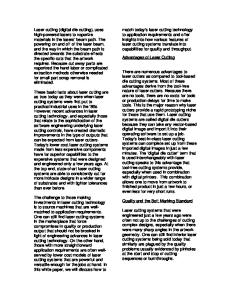
The experimental setup of the LDA includes the same configuration of the nozzle positioning system and the working piece as described in section 2.1 The commercially available LDA system (DANTEC, Germany) is based on an optical system to measure the particle velocity in a supersonic flow. The velocity distribution of sprayed particles was measured in a 2D field. The size of a measured point has a volume of 0.02 mm3. The data were accumulated over 15 s time duration or over 2’000 data points. The data interpolation results in a 2D LDA mapping of a velocity distribution over an area of 12 x 8 mm2. The velocity distribution of various nozzles at different nitrogen pressures and two nozzle distances (0.5 mm and 1 mm) were measured. The limitation of this method was the accurate control of the dispersed particle size. The supersonic flow dynamics depends on particle size, especially in the area where shock waves are located. A sensitivity analysis has also shown that the nozzle position relative to the kerf is very sensitive. As consequence the position of shock waves was shifted. Nevertheless, qualitative results about the influence Fig. 1 Experimental setup of LDA measurement of the gas flow dynamics of different nozzles designs as well as the influence of different process parameters could still be obtained. 2.3
CFD Simulation of gas flow
The shear-stress transport (SST) model as standard turbulence model of CFD calculation was used as theoretical model of the gas nozzle with the CFX-5.5-Solver of the commercially available CFX 5.6 program (AEA-technologies). A higher resolution was achieved with the hexaeder net generated with the ICEM CFD net generator when comparing with results of a tetraeder net. Following assumptions were made: - 3D compressible gas flow with possible shock waves, turbulence or flow separation - the inner geometry of various nozzle types were consider - the setup of nozzle positioning system were consider in the same configuration with a working piece like in experiments (see 2.1) - the wall roughness of the kerf was not considered - the temperature distribution along the kerf and working piece was not included
- the optical system, the laser or any reflectivity of the environment was not included - the existence of liquid or vapour gas phase of cutting material are neglected The boundary condition outside the nozzle is defined as a cylinder with ambient pressure along the boundary. The starting point of the calculation was the solution of the stationary condition at an input pressure of 0.2 MPa. Converging solutions of the transient calculations were stepwise generated from 0.2 MPa to 2.0 MPa. The 2D distribution of velocity gradients, mass flow density or shearing stress were calculated for different nozzles for a pressure range up to 2.0 MPa. 2.4
Real life test of various nozzles for the laser cutting process
Various nozzles were tested in laser cutting experiments with the Bystronic Laser 5200arc at a nitrogen gas pressure range up to 2.0 MPa. Only stainless steel of 10 mm thickness was used for the systematic studies of the influence of the process parameter. Gas nozzle distance (s), focus length (f) and cutting speed (v) were varied in a small range to study the influence of these process parameters on the cutting quality. A 1D scan measurements of roughness has been used in conjunction of 2D photographs giving complete and comprehensive information about the cutting quality. The cutting surface images were then compared with the 2D distribution of gas velocity or the density gradient measured by LDA and CFD simulations to understand the effect of the gas flow dynamics on the cutting quality. Following nozzle types with an equal outlet diameter were used for all studies: conic nozzle, ring nozzle, supersonic nozzle with conic-divergent inner geometry.
3
Results
The following tables summarize selected results of a systematic studies of the gas flow dynamics along a laser induced kerf using different nozzles designs. ‘Schlieren’ photographs, 2D LDA mapping, CFD simulations and real life cutting experiments were used for the analysis. Primarily, the influence of increase gas pressure up to 2.0 MPa were studied on the gas flow dynamics. The value of nozzle distance depends on material type, its thickness and is adapted to the focus length. In our experimental set the nozzle distance was varied otherwise all other optimal adjusted parameters held constant. The simple variation of this process parameter is favourably to verify the results of the CFD simulation with the ‘Schlieren’ photographs. The changes of the flow dynamics were clearly seen over the whole pressure range. Tab. 1 shows the comparative results of two nozzle designs with different nozzle distance for a defined gas pressure using the ‘Schlieren’ technique. The gas pressure and the nozzle distance have a strong influence on the gas flow dynamics. Both parameters have been studied thoroughly.
Tab. 1: Influence of two nozzle distances to the metal sheet for a conic and a ring nozzle on the gas flow dynamics at a nitrogen gas pressure p = 1.0 MPa visible in ‘Schlieren’ photographs Nozzle shape Conic
‘Schlieren’ photograph @ s = 0.5 mm
‘Schlieren’ photograph @ s = 1.0 mm
Ring
The influence of nozzle distance to the working piece (s = 0.5 mm and 1.0 mm) was studied in a pressure range of 0.5 to 2.0 MPa. The pictures show the nozzle (top) and the gas flow along the kerf (left) visualized with the ‘Schlieren’ method. In reality, the cutting direction would be from the left to the right. The red marked ellipse indicates the gas flow separation along the kerf. When comparing the ring with the conic design, it can be observed that the ring design has a smaller flow separation field and a lower reflection point along the kerf than the conic design. Also, a decrease in working distance is leading to a smaller flow separation field at the kerf. It is assumed, that a low reflection point is preferable for an efficient nozzle design due to the better drive out of molten material.
Local changes of gas density result in the formation of shock waves, visible as shadows in the ‘Schlieren’ photographs. These density changes are also shifted to the lower edge of working piece for the ring nozzle compared to the conic nozzle. Tab. 2: Comparison of the gas flow dynamics with ‘Schlieren’ photographs, CFD simulation, LDA measurements and with the real life cutting experiments. Results are presented for a conic, a ring and a convergent-divergent nozzle. Identical process parameters were used for all methods (nozzle distance = 0.5 mm, nitrogen gas pressure p = 1.6 MPa, material = stainless steel = 10 mm, cutting speed = 1’400 mm/min, laser power = 5.2 kW. Conic nozzle
Ring nozzle
Convergent-divergent nozzle
‘Schlieren’ photograph
Distribution of gas velocity calculated by CFD simulation 2D LDA mapping @ 1.5 MPa
Photographs of the laser cutting surface The ‘Schlieren’ photographs and the velocity distribution calculated by CFD simulation show a good match concerning the gas flow dynamics for all nozzle types and at different gas pressures (Tab. 2 shows only p = 1.6 MPa). This includes the qualitative distribution of velocity and the reduced mass flow density calculated with CFD simulations, the formation of special shadows like shock waves, the position and the area of the reflection point observed in ‘Schlieren’ photographs. The distribution of gas density and velocity distribution observed by ‘Schlieren’ technique and LDA as well as the CFD simulation is qualitatively comparable. When comparing the experimental method LDA with CFD simulations, the maximum of the gas
velocity differs about 20 %. However, the LDA method seems not to match as clearly as the Schlieren photographs, this is most probably due to the restricted reproducibility (the variation in particle size) of the LDA measurements and limited accuracy when positioning the nozzle. The cutting quality and the tolerance range of the process parameter to achieve best cutting quality is a direct indicator of any improvement of the gas dynamics of the various nozzle designs. The table shows the correlation of various nozzle designs with the achieved cutting quality for one set of process parameters. The formation of a brow, its shape, length and direction of the brow is a consequence of not successfully removed molten material. With the ring nozzle a high tolerance to variation in the process parameter were observed as well as that the highest cutting quality was achieved. The measurements of the roughness coefficients did not show any difference between all three nozzles design and is therefore not a suitable tool for designing new nozzles. The parameter with the greatest influence on the surface quality is the nozzle distance and the gas pressure comparing the other process parameters focal position or cutting speed under equal condition. A remarkable influence of focal position on cutting quality was detected at higher pressure. However, no clear influence of the cutting speed on the formation of burr has been observed with increased gas pressure while the other process parameter fixed. The best results have been achieved with the nozzle with the smallest flow separation at the lowest reflection point, steepest angle of the gas flow and shock wave formation below the metal sheet. This is the case for the ring nozzle, which shows also the best cutting performance over a wide range. CFD simulation in conjunction with the Schlieren method are an efficient tool to map the gas flow dynamics and design new nozzles with even better performance as shown in Tab. 2. Based on these results an new nozzle (not shown) has been designed, which led to quality cuts at 25% reduced gas pressure (comparing conic nozzle) when cutting stainless steel. Also, the cutting speed could be increased up to 30 % simultaneously. More extensive testing in different materials with various thickness will be performed in the future. A patent application is in process.
5
Conclusion
Important and extensive information about the gas flow dynamics were gained as a result of the study of various nozzles and several experimental and numerical methods. The comparison of the observed gas flow dynamics in ‘Schlieren’ photographs with results of CFD simulations show a very good agreement and is therefore a suitable and efficient tool when designing nozzles for laser cutting applications. The use of well-known experimental methods comparing with a theoretical model, which visualized the gas flow as 2D distribution of velocity gradients, mass flow densities or shearing stress by numerical calculation, resulted in a better understanding and led to a new nozzle design with an efficient gas flow for laser cutting.
6
Acknowledgements
The study and the development of laser cutting nozzles were realized in collaboration between the Bystronic Laser AG and the Institute of Thermo- and Fluid Engineering of the FACHHOCHSCHULE Aargau. This work was supported by the KTI/CTI (Swiss innovation promotion agency) under the contract No. 6359.2 FHS-IW.
References [1]
[2] [3] [4]
[5] [6] [7]
[8]
R.Edler, P.Berger: New Nozzle Concept for Cutting with High Power Lasers. In: Laser Institute of America (Hrsg.): Proc. of the Laser Materials Processing Symposium ICALEO’91, San Jose. Orlando: Laser Institute of America (LIA), Vol. 74 (1992) 253 – 262 W. Masuda, E. Moriyama: Aerodynamic Characteristics of Underexpanded Coaxial Impinging Jets. JSME International Journal, Series B, Vol. 37, No. 4 (1994) 769 – 775. K. Chen, Y. Lawrence Yao, V. Modi: Gas Jet – Workpiece Interactions in Laser Machining. J. Man. Sci. Eng. Vol. 122 (2000) 429 – 438 H.C. Man, J. Duan, T.M. Yue: Modelling the laser cutting process: Mathematical modelling of the cut kerf geometry for the laser fusion cutting of thick metal (I). J. Phys. D, Vol. 34 (2001) 2127 – 2134 H.C. Man, J. Duan, T.M. Yue: Modelling the laser cutting process: Distribution of supersonic gas flow field inside the cut kerf (II). J. Phys. D, Vol. 34 (2001) 2135 – 2142 H.C. Man, J. Duan, T.M. Yue: Modelling the laser cutting process: Effects of various process parameters on cut kerf quality. (III). J. Phys. D, Vol. 34 (2001) 2143 – 2150 G.S. Settles: Schlieren and Shadowgraph Techniques. Visualizing Phenomena in Transparent Media. R.J. Adrian, M. Gharib, W. Merzkirch, D. Rockwell, J.H. Whitelaw (all Ed.) In: Experimental Fluid Mechanics. Springer-Verlag Berlin Heidelberg New York, (2001) 20 – 37 C. Mas, R. Fabbro, Y. Gouedard: Steady-state laser cutting modeling. J. Laser Applications, Vol. 15, No. 3 (2003) 145 – 152