HIGH SPEED LASER CUTTING OF ELECTRODES FOR ADVANCED BATTERIES M902 1
1
1
1
Rahul Patwa , Hans Herfurth , Henrikki Pantsar , Stefan Heinemann , 2 2 Jyoti Mazumder , Dongkyoung Lee 1
Fraunhofer Center for Laser Technology, 46025 Port Street, Plymouth, 48170, MI 2 University of Michigan, College of Engineering, Ann Arbor, MI
Abstract Lithium-ion batteries are at the forefront of current advanced battery technology development for Hybrid-Electric Vehicles (HEV). While first vehicles with Li-ion batteries have entered the market, it is understood that significant technology advancements are still required to establish consumer confidence in the new battery technology and to reduce battery cost for serving a broader market. The sizing of electrodes is an important step in the manufacturing chain of Lithium-Ion batteries. Compared to mechanical die cutting, contact-free high speed laser cutting has the potential to offer significant advantages with regard to flexibility and edge quality to the sizing operation. Main challenges include the composite electrode material and high demands on edge quality. The University of Michigan and Fraunhofer are collaborating on the development of high speed laser cutting of electrodes using single mode fiber lasers. The program aims at cutting speeds in access of 100m/min and includes process modeling of the laser-material interaction and the laser formed cut surface as well as experimental studies to minimize the thermal impact on the electrode materials and to optimize the cut quality. This paper will present initial results on the modeling and parameter development effort. Introduction The automotive sector is strongly motivated to address the consumer demand for more fuel efficient cars and to accelerate the electrification of future powertrains. Especially, in the US and Japan the market for hybrid electric vehicles (HEVs), plug-in hybrid electric vehicles (PHEV’s) and electric vehicles (EV) is rapidly expanding. These vehicle systems combine the benefits of high fuel economy and lower emissions with the power, range, and convenience of gasoline and diesel powered vehicles ICALEO® 2010 Congress Proceedings
[1]. According to a report by The Boston Consulting Group [2], an estimated 14 million electric and hybrid cars may be sold in 2020 in the world's four largest automotive markets - Western Europe, North America, Japan, and China - up from 1.6 million in 2009. One of the enabling factors for the development of new hybrid systems for vehicles are significant advancements in battery technology [3]. In recent years considerable progress has been made in the development of advanced batteries with regard to efficiency and power output and many developers currently pursue the Lithium-ion battery chemistry as being the one best suited for meeting HEV requirements regarding weight, capacity and energy density [4]. Future PHEVs and EVs will require even lighter, more compact, and higher-capacity batteries to achieve the targeted driving range. Most developers believe that the lithium-ion batteries can address these challenges as they can store up to three times more energy, generate twice the power and can store twice as much energy per liter of volume compared to other batteries used today [1]. In addition to reliability and safety, battery cost will play an important factor for a broad market acceptance of hybrid systems utilizing lithium-ion technology. Battery pricing will be significantly impacted by material cost and manufacturing cost in mass production. Current limitations of the applied manufacturing technologies for battery manufacturing are based on the process capabilities with regard to throughput, quality and cost. Laser processing is proven in industry as a highly efficient and reliable manufacturing method that can potentially contribute to significant cost savings and quality improvements. In this paper, our investigation on high speed laser cutting of electrodes for advanced batteries has been discussed to address some of these key concerns. Contact-free laser cutting of electrode materials has been investigated with the objective to determine the achievable cut quality and potential cost benefits compared to mechanical die cutting. Laser Materials Processing Conference
Background Lithium-ion battery electrodes are made from active material coated on both sides of aluminum and copper foils that serve as current collectors (Figure 1). Foil thicknesses can range from 0.01 mm (uncoated) to 0.2 mm (coated) depending on the cell design (cylindrical or planar) and the electrode type (cathode or anode). Our development efforts were directed towards laser cutting of planar electrodes. As opposed to cylindrical cells where the slitting is performed in the uncoated section of the current collector foils, planar electrodes are cut from wider webs that are entirely coated with active material. This alternative battery cell design provides more design flexibility and can therefore be easier customized for specific applications. . Die cutting is currently used to stamp planar electrodes and rotary knife slitting is applied to size electrode strips for cylindrical cells. Both techniques require relatively expensive tooling that wears over time resulting in process instabilities and poor cut quality. Specifically, slight bending of the cut edge and the formation of micron sized material attachments can result in short circuits and catastrophic failure of the complete system. Therefore, frequent maintenance and tool replacement are required.
Photo: Fh-ISIT Figure 1 Electrode material for lithium-ion batteries In conventional laser cutting, the cutting head includes fixed beam delivery optics, cutting gas delivery system, vision system and other options as required by specific cutting processes. The focusing optics focuses the collimated laser beam on the workpiece to a small spot size. A nozzle placed at the end of the cutting head has a very small opening to supply assist gas that ejects the melt from the cut kerf. The cutting head is typically mounted on a robot or on the vertical axis of a CNC machine tool system. Such a machine tool system must meet ICALEO® 2010 Congress Proceedings
stringent system requirements regarding precision, accuracy and repeatability at high cutting speeds. Remote cutting technology is a relatively new laser cutting process. The two essential components that have lead to the success of remote cutting technology are advancements in (1) optical beam scanning systems and (2) high brightness lasers. Well established galvanometer scanner technology comprises of high-performance rotary motors that produce high dynamic beam deflection. The low mass and inertia of these systems enable achieving high speeds and acceleration of up to10g. Up to 15 m/s can be achieved with latest digital scanners. The image field size and the working distance is directly proportional to the focal length of the F-Theta focusing lens. In order to generate larger image field size, longer focal length is required which in turn require better beam quality to generate small spot sizes. With the availability of high power and high brightness lasers such as fiber and disk lasers with excellent beam quality it is possible to achieve very small spot sizes < 20µm with high power intensities (>108 W/cm2 ). Larger image field sizes enable very flexible cutting processes which can accommodate different electrode shapes and sizes while keeping the electrode stationary. Therefore, high accuracies and repeatability can be achieved. If the electrode size is larger than the image field size then electrode or scanning system or both need to be moved relative to each other. This process is called on-the-fly cutting. Accuracies and repeatability could be limited with this technique. In remote laser cutting, the material is cut by combination of very high energy densities in very small laser spot and very high speed beam movement; it does not require any cutting gas as the melt in the cut kerf is partially vaporized and partially ejected by very high vapor pressure under extreme conditions of temperature and melt pool dynamics. High cutting speeds results in very short cycle times and minimum heat effected zone given the thermal nature of the process. This is especially important for thin materials where conventional laser cutting has its limitations and a larger thermal effect on the part. In contrast to scanning systems, a conventional laser cutting machine requires significant capital investment for fast moving linear axes systems. These systems are more bulky and massive, take more work space, their accuracy is low and decreases further as their size gets larger. Moreover, dynamics of system constrains the maximum possible speed
Laser Materials Processing Conference
and acceleration. The programming of the cutpath also requires special attention as the geometry of cutting path gets complex. High cutting speed and high cut quality can be achieved in conventional laser cutting , however optimization of a large number of process variables that affect the cutting quality is required. Besides common process parameters such as laser power, speed, spot size etc, for both conventional and remote laser cutting process, there are a number of other critical factors that affect the cut quality only in conventional cutting process such as nozzle size, distance of nozzle tip to the top of material surface, cutting gas type, gas pressure, flow rate etc.
high speed galvo-scanner. A 500W single mode (SM) fiber laser beam was fiber-delivered and collimated before it enters the scanner . An 80 mm F-theta lens focuses the beam such that it creates a square scanning field with a maximum size of 37.5 X 37.5 mm2 .
Pulsed cutting with high peak power lasers using similar scanning optics can be applied to minimize the heat affected zone. However, compared to remote cutting the achievable cutting speed is significantly lower due to limitations in the available power and the maximum repetition rate [6]. Remote laser cutting using cw lasers is being increasingly applied for cutting both metals and nonmetals. Cutting of battery electrodes is a suitable application for laser remote cutting process for a number of reasons:
Figure 2 Schematic of remote laser cutting process
− Electrodes are made of thin foil material with less than 0.2mm thicknesses such that single pass remote cutting is possible. − The process is very flexible. Different electrode designs can be easily cut by changing the scanner program. (Typically, flexible electrode designs require flexible cutting process. In case of remote cutting, design change can be as simple as a program change in the scanner software.) − Remote cutting has no geometrical design constrains regarding shape and can cut complex geometries on planar electrodes. However, the maximum size of the electrode is restricted by the image field size of the scanner. − Straightforward integration of such a cutting system into production.
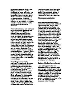
Experimental Set-up Figure 2 shows the schematic of remote laser cutting process and Figure 3 shows the cutting of round electrodes in action. Cutting was performed using a scanning optic and stationary electrode; the laser beam was moved across the electrode surface using a ICALEO® 2010 Congress Proceedings
Figure 3 Remote laser cutting of round electrodes Since very high vapour pressures are present in this cutting process, it was essential to hold the electrode flat on the fixture during the entire cutting process. This was achieved by using a vacuum plate to hold the electrode. A narrow groove < 0.5 mm was placed right under the electrode where the cutting takes place. This prevents any attachments of melt that moves out of cut kerf to the fixture plate. Since the Rayleigh length of laser beam is small, the bottom surface of the groove was not effected by the high power laser beam and therefore does not produce any Laser Materials Processing Conference
dust that might otherwise contaminate the electrode surface. Constant distance between scanner optic and electrode top surface is maintained during the entire cutting process. It is important to properly fixture and handle electrodes to avoid any damage either before or after the cutting process. Cutting was performed in a clean and dust free environment with suitable fume exhaust systems. No process gas was used for cutting process. Table 1 lists two types of current collector foils, three different types of anodes and three different types of cathodes that were investigated along with their corresponding thickness. Table 1 Different type of electrodes Electrode
Description
Cu foil Al foil Anode 1 Anode 2 Anode 3 Cathode 1 Cathode 2 Cathode 3
No coating No coating Graphite Graphite Graphite Li oxide LiFePO4 LiCoO2
Total Thickness (µm) 10 15 70 70 140 170 100 150
the surface of the material. No change occurs on the bottom side of the material. With increasing laser power the cutting process changes to through but incomplete cutting along the length of the cut. This is identified by small tab-like features that were randomly spread along the length of the cut. These tabs are bridges of material between both edges formed from either coating or metal foil or combination of both. Larger tabs are formed when the laser power is increased just above the no cutting threshold. Further increase in laser power results in smaller tabs. Both larger and smaller tabs can be identified visually by facing the laser cut kerf towards a light source. Very fine tabs are formed when laser power was slightly lower than the optimum power level required for through cutting along the entire length of cut. These fine tabs could break either right after the cutting process was finished or during the handling of the electrode afterwards. A close examination under a microscope is required to locate very fine tab features or its remnants. The formation of tabs is more pronounced at higher thicknesses.
Process Development A series of linear cutting tests were conducted to determine the parameter window for laser cutting of current collector foils and coated electrodes. In remote laser cutting, process parameters that require optimization are laser power, cutting speed, line energy, focus position, spot size and number of cutting passes. Each of these parameters was optimized for different electrodes and their effect on cutting process was analyzed. In order to understand the laser power requirement for cutting different electrodes, laser power was increased incrementally from a very low power level while speed was kept constant until through cutting or full penetration cutting was achieved. For all types of materials and thicknesses, the cutting process showed a gradual progression from ‘no cutting’ to ‘through cutting’. This gradual change in process was marked by transition steps between these two processes. At very low laser power, no cutting process was established. The laser beam was passed once over the material which could be identified by a mark left on
ICALEO® 2010 Congress Proceedings
Figure 4 Laser power and speeds for cutting different electrodes Figure 4 shows the variation of required laser power as a function of cutting speed. Higher laser power is required for through cutting of electrodes at higher speeds for all investigated electrode materials irrespective of their type and thickness. The rate of this increase is dependent on the material type, material thickness and the cutting speed. Maximum cutting speeds for Anode 1, Anode 2 and Anode 3 are 5, 3 and 2 m/s respectively. Anode 2 was cut at less than 200 W while >450W was required for cutting Anode 3 which is more than twice as thick. Maximum cutting speeds for Cathode 1 and Cathode 2 is 4 and 3 m/s respectively. The maximum speed
Laser Materials Processing Conference
tested for cutting was limited to 5m/s. In general, as the material thickness increases the laser power required for through cutting increases at a faster rate. An exception is the cutting of uncoated metal foil. For cutting copper and aluminum foils, higher laser power was required than cutting Anode 2 although thickness of Anode 2 is multiple times higher than the copper and aluminum foil thickness. The reason is the low absorption of the copper and aluminum surfaces compared to the active electrode materials that have a high carbon or metal-oxide content. Copper and aluminum foil can both be cut at 5m/s using 322 W and 371 W respectively. Interestingly, through cutting of Cu foil was achieved at laser power equal to the power that was required for cutting Anode 1 at speeds > 3 m/s. This is a suitable cutting condition when a planar electrode has both coated and uncoated parts that can be continuously cut without changing parameter settings.
multiple times higher thickness. Moreover, Anode 1 and Anode 2 have same thickness but their line energies requirements are very different. Therefore, electrode composition and properties are also important factors that need to be taken into account for estimating line energy requirements besides electrode thickness. Figure 5 also show the standard deviation of the line energy. Note that the maximum deviation value corresponds to copper foil. Higher reflectivity of copper surface to laser radiation could cause such deviation. Due to high reflectivity, at lower laser power, the coupling of laser radiation with the copper surface is less stable. Therefore the deviation in line energy is higher when cutting copper foil. For electrodes, the high carbon content of the coating increases the absorption of the laser radiation in material and facilitates a more stable cutting process.
A complete cut of Cathode 3 was not achieved even at maximum power of 500W and reduced speed of less than 1 m/s.. Very fine intermittent tab features were always attached to both sides of cut kerf.
Figure 6 Beam radius required for through cutting
Figure 5 Line energy required for through cutting Line energy is the ratio of laser power to the cutting speed. It is used to compare energy requirements for different materials when both, laser power and cutting speed are changed simultaneously. The average line energy required for through cutting is calculated by averaging the ratio of laser power to the cutting speed at different cutting speeds (Figure 5). Anode 3 requires the maximum average line energy of 250 J/m and Anode 2 requires the lowest line energy less than 50 J/m. There is no clear relationship between the electrode thickness and line energy required for cutting. For example, although material thickness of Cathode 2 is higher than that of Anode 3, it requires 30% less line energy. Similarly, both copper and aluminum foil require higher line energy than electrodes Anode 1 and Anode 2 that have ICALEO® 2010 Congress Proceedings
By moving the focus position of the laser beam normal to the material surface, the laser spot size on the surface of the material can be changed. During the process setup, laser focus position was determined by conducting focus measurement tests and focus position was set as zero position. A vertical axis was used to move the material position above or below this zero position. The solid line in Figure 6 shows the change in the laser beam radius as a function of its distance from the focus position, which was determined earlier by caustic measurement of the beam. For different electrodes, the beam radius was changed by changing the focus position to achieve through cutting. Different beam radii corresponding to different materials that can cut through the material are shown in Figure 6. Anode 1, Anode 2 and Cathode 1 are cut at focus position “0”, which is at the surface of the material Laser Materials Processing Conference
using a spot size of 11 µm. Laser spot diameter > 50 µm is required for cutting Cathode 3. This spot size was achieved by positioning the laser beam 0.4 mm below the surface. Furthermore, it was found that a spot size >40 µm is required to cut Anode 1 and Cathode 2. This corresponds to a focus position of 0.26 mm below the surface. Intermittent laser cutting was achieved at smaller spot sizes. Similar cutting results were achieved for using the same spot sizes independent of selecting a positive or negative focus position. Single laser pass cutting is the preferable cutting method as overall higher cutting speeds can be achieved. Also, positioning accuracy and repeatability requirements of laser spot are reduced and are determined only by requirements on accuracy of part geometry. However, for thicker electrode types, the multiple pass cutting leads to higher cut quality with lower thermal effects.
In Figure 7, the red circles correspond to the number of passes (secondary right vertical axis) required for through cutting of Cathode 3 at different laser power. It is clear that ‘through cutting’ is possible only at higher laser power using fewer number of passes. The curve fit trend line for number of passes has a linear slope and therefore represents a constant relationship between the laser power and required number of cutting passes to cut through the material. Nevertheless, the total line energy required for cutting through a particular material was less dependent on the power and the number of passes and evidently depended more on the type and thickness of material. In the Figure 7 ‘through cutting’ for different electrodes i.e. Cathode 3, Cathode 2 and Anode 2 is achieved at different total line energies. But the variation of total line energy as a function of laser power is relatively small compared to its mean value even though both the laser power and the number of passes are changed. This means that required number of passes can be easily determined for any laser power if the total line energy to achieve through cutting is known for a given material.
Face View Figure 7 Total line energy and laser power for multiple pass remote cutting of thicker electrodes Figure 7 shows the effect of multiple pass cutting for thicker electrodes. The black markers (squares, diamonds and triangles) correspond to the total line energy (left vertical axis) for three different electrodes at different laser power and number of passes. Cutting speed was kept constant at 5 m/s. Total line energy has been calculated using following relationship:
Top View
Total line energy = (Laser power * Number of passes)/ (Cutting speed)
Figure 8 Remote laser cut edge of Anode 1
Although the gain in the higher speed is partially offset by the multiple passes that are required to cut through the electrode material, this process provides better control of the energy input into the material. Each pass of laser beam removes a part of electrode layer immediately followed by next pass.
shows face view and top view of a remote laser cut edge of Anode 1. Cutting was performed at 5m/s (300 m/min). The cut edge looks very good exhibiting no delamination between the current collector foil (center) and the coating. The top view shows that only a very small part of the current
ICALEO® 2010 Congress Proceedings
Laser Materials Processing Conference
collector is exposed and no burrs are formed. Further investigation of the edge quality is required to determine any degradation of the electrode material and its bond to the current collector that could possibly impact the long term durability and functionality of the battery cell.
electrode under high temperature or high current conditions. The special prototype button cell is made of round laser cut electrodes with a size of 20 mm diameter.
Process Modelling The ongoing modelling effort is focused on developing a fundamental understanding of the laser beam material interaction in remote laser cutting of electrode materials. The 3-dimensional process model takes various physical phenomena such as melt flow, temperature and pressure distribution, melting, mushy-zone, evaporation, and multiple reflections into account and applies computational techniques such as level-set method and ray tracing methods to track the liquid-vapour interface into account. Measurements of the cut kerf and temperature and plasma analysis are used for validation. The model will allow to study the influence of process parameters on the cut quality, specifically on the heat affected zone and will provides input to the experimental studies for further process optimization. The investigation of the laser-material interaction through simulation is an essential step since melt pool dynamics during the processes have huge impact on the qualities of the processed products. Furthermore, the simulation could provide a guideline to find the proper operating laser parameters. The initial work has been conducted for uncoated copper and aluminium foils. which are sandwiched between the coatings of electrodes and act as the current collectors for anode and cathode, respectively. These materials are chosen because the understanding of the behaviour of the core materials of the electrodes is prerequisite to expand the model development investigation to multilayer materials. The simulation results provide laser parameter thresholds to distinguish full penetration cutting and no cutting. Detailed description of the mathematical model and results are presented in a separate paper at this conference [7]. Process Validation In addition to the microscopic characterization (SEM) of the cut quality, the electrochemical properties of laser cut electrodes are being investigated using button cells. The thermal impact on the material at the edge can lead to degradation of properties that effect the stress behavior of the ICALEO® 2010 Congress Proceedings
Figure 9 Round electrode (Ø20 mm) cut out of Anode 1. (Speed – 3 m/s; Power – 270 W; Cutting time -25 ms) Parameters optimized for straight line cutting were adapted to the round geometry. No difference in cut quality was observed when cutting was performed on round electrodes (Figure 9). (Since the size of electrode is smaller than the image field of the scanner, no movement of the electrode relative to the foil was necessary. Once the laser and scanner delays were optimized, no start/stop effects of cutting process such as mismatch were noticed. Very high repeatability of part shape and size was achieved. Summary and Conclusions Lithium-ion battery technology is considered the best suited technology for meeting the future hybrid and electric vehicle requirements regarding weight, capacity and energy density. However, in order to achieve broader market acceptance, highly efficient manufacturing processes are required to lower cost. In this study, laser remote cutting process was investigated on six different electrode materials and two different current collector foils. Anode 1, Anode 2, Cu foil and Al foil current collector were cut at maximum speed of 5m/s (300 m/min). Maximum cutting speeds of more than 2 m/s (120 m/min) were achieved for most materials Multiple laser passes were used to cut thicker electrodes. Cathode 3 was cut using five consecutive cutting passes. The laser cut edges are of good and consistent quality in initial characterization. A brief description of the process model under development is presented. Round battery electrodes were cut using optimal parameter settings. As a next step, button test cells are being assembled and subjected to extensive Laser Materials Processing Conference
testing to further evaluate the quality and cycle life of laser cut electrodes. References [1] Muller, J. & Stone, A. (2008) Jump Start, Forbes. [2] The comeback of the electric car? How real, how soon, and what must happen next (January 2009), Boston consulting group report. [3] Herfurth H.J. (May 2009) Building better batteries, Industrial Laser Solutions. [4] Alamgir, M. & Sastry, A.M. (2008) Efficient Batteries for Transportation Applications, in Proceedings of the SAE Convergence, Detroit, MI. [5] Herfurth H.J., Patwa R., Pantsar H., Heinemann S. and Newaz G. (2008) Laser processing for alternative energy devices: Advanced battery and fuel cell applications, in Proceedings of the ICALEO, Temecula, CA. [6] Herfurth H.J., Patwa R., Pantsar H. (2010), Laser cutting of electrodes for advanced batteries, in Proceedings of the LPM, Germany. [7] Lee D., Mazumder J. and Herfurth H. (2010), The numerical studies of the laser processing parameters on copper and aluminum during laser cutting, in Proceedings of the ICALEO, CA. (To Be Published)
Meet the Author(s) Rahul Patwa is currently working as a project engineer at Fraunhofer Center for Laser Technology at Plymouth, MI. His current focus is on laser processing and process monitoring applications. He received his MS degree in mechanical engineering from Purdue University at West Lafayette in 2004.
ICALEO® 2010 Congress Proceedings
Laser Materials Processing Conference