Diss. ETH No. 17323
Intra-Body Communication for Biomedical Sensor Networks A dissertation submitted to the ETH ZURICH for the degree of Doctor of Sciences presented by MARC SIMON WEGMÜLLER Dipl. El. Ing. ETH born 20. September 1977 citizen of Switzerland accepted on the recommendation of Prof. Dr. Wolfgang Fichtner, examiner Prof. Dr. Peter Niederer, co-examiner Prof. Dr. Niels Kuster, co-examiner 2007
Acknowledgments First of all, I would like to thank my advisor Prof. Dr. Wolfgang Fichtner for his support, for his faith in my work, and for enabling collaboration with all external project partners. I am grateful to Prof. Dr. Peter Niederer for co-examining this thesis. I wish to express my gratitude to Prof. Dr. Niels Kuster and the Foundation for Research on Information Technologies in Society (IT’IS) for their support during the entire research project. Very special thanks go to Prof. Dr. med. Otto Hess, Cardiology Insel University Hospital, Bern, who offered to conduct the clinical trial. Also from Insel University Hospital, I would like to thank my colleague Adrian Lehner for organization and support during the entire clinical study. My deepest gratefulness belongs to Dr. Michael Oberle. He has accompanied me for several years as a mentor. We began the research on body communication thanks to his initial ideas. The numerous discussions with him and his advice have been an invaluable contribution to my efforts in further developing models and systems for intra-body communication. I would like to address my special thanks to Dr. Juerg Froehlich. This work would not have been possible without his ideas and input on numerical simulation. Moreover, Juerg offered his help and support much further than only in the technical profundities of numerical models. For numerous contributions in the field of numerical simulations I would like to thank Joanna Olszewska, former member of IT’IS, and Andreas Kuhn, Automatic Control Laboratory (IfA). The successful and close collaboration with both showed that cooperation in my interdisciplinary research field can be incredibly fruitful. v
vi At the Integrated Systems Laboratory (IIS) I would like to thank Dr. Norbert Felber and, from the Microelectronics Design Center, Dr. Hubert Kaeslin. They both introduced me to the field of digital VLSI design and motivated me to start my PhD work by combining VLSI with complementary applications such as offered by biomedical research. I am extremely grateful to my colleagues from IIS: I shared not only the office but many interesting and fruitful discussions with Chiara Martelli, Flavio Carbognani, and Felix Buergin during the last 3 years. The exchange inside the digital group was enriching. Many thanks to the entire MIMO group with Dr. Andy Burg, David Perels, Simon Häne, Peter Lüthi, Stefan Eberli, Markus Wenk, and Christoph Studer. The idea exchange with the members of the Bio Electromagnetics and EMC group greatly complemented my work. Special thanks to Dr. Juergen Schuderer, Sven Ebert, Stefan Benkler, Verónica Berdiñas Torres, and Peter Müller. In addition, I would like to mention Frank Gürkaynak and Matthias Braendli who have become very good friends. Among the many students I supervised over the years, I would especially like to mention the group with Tobias Blaser, Stephan Senn, and Philipp Stadelmann plus the work of Martin Hediger and Thomas Kaufmann. The discussions and work with them have been a great pleasure and resulted in very valuable research contributions. Hanspeter Mathys and Hansjörg Gisler supported me with their craftsmanship and with their friendliness. I wish to especially thank Dr. Dölf Aemmer and Christine Haller for their administrative efforts on my research project shared between IIS and IT’IS. Furthermore, I want to acknowledge the efforts carried out at IT’IS by Jaqueline Pieper and the proofreading by Michelle Stubbs. In the end, my deepest thanks go to my parents Ursula and Rolf Wegmüller for all the care and support they gave me in the last years. They are the best parents I can imagine. Thanks also to my brother David who has been a friend and a good listener in many discussions through our entire lives. Zurich, July 2007
Marc Wegmüller
Abstract Intra-body communication is a novel data transmission method that uses the human body as an electrical channel. The idea is driven by the vision of a cable-free biomedical monitoring system. On-body and implanted sensors monitor the vital functions and transfer data through the human body to a central monitoring unit. Especially for risk patients and long-term applications, such a technology offers more freedom, comfort, and opportunities in clinical monitoring. In this thesis, the human body is characterized as a transmission medium for electrical currents by means of the dielectric properties and the developed electrical models of human tissue. Numerical finite-element simulations are compared to in vivo measurements. For that purpose, a sophisticated measurement hardware has been developed that applies alternating 1 mA peak current in the promising frequency range of 10 kHz to 1 MHz. The individual-specific variations of the transmission characteristics have been investigated in a clinical trial. The subjects’ extra-cellular and intracellular water distribution and skin condition have been identified as the most significant indicators. Overall, the thorax features reasonable transmission characteristics with an averaged attenuation of 55 dB and a typical SNR of 20 dB, while the extremities and joints cause poorer transmissions. Finally, this work proposes transmitter and receiver architectures for intrabody communication. Data transfers of up to 64 kbit/s with BPSK modulation have been achieved through the human body. The first VLSI implementation of a modified SPIHT algorithm offers compression ratios of up to 20:1 for ECG signals still containing all significant details for medical diagnosis. The implementations fulfill all biomedical requirements on galvanic coupling into and within the human body. vii
Zusammenfassung Intra-body Kommunikation ist eine neuartige Datenübertragungsmethode, die den menschlichen Körper als elektrischen Kanal benutzt. Die Idee basiert auf der Vision eines kabellosen Monitoringsystems. Auf dem Körper getragene und implantierte Sensoren zeichnen die Vitalfunktionen auf und übertragen die Daten durch den Körper zu einer Zentraleinheit. Speziell für Risiko- und Langzeitpatienten offeriert die Technologie mehr Bewegungsfreiheit, Komfort und Möglichkeiten in der klinischen Überwachung. In dieser Arbeit wird der menschliche Körper als Übertragungsmedium für elektrische Ströme anhand von den dielektrischen Eigenschaften und elektrischen Modellen des Gewebes charakterisiert. Numerische Finite-Elemente Simulationen werden mit in vivo Messungen verglichen. Dazu ist eine Messhardware entwickelt worden, welche alternierende Ströme von 1 mA im vielversprechenden Frequenzbereich von 10 kHz bis 1 MHz appliziert. Die Individuum spezifischen Schwankungen sind in einer klinischen Studie untersucht worden. Die extra-celluläre und intra-celluläre Wasserverteilung und die Hautbedingungen der Versuchspersonen sind als die signifikantesten Indikatoren erkannt worden. Insgesamt weist der Thorax eine gemittelte Dämpfung von 55 dB und ein typisches SNR von 20 dB auf, während die Extremitäten und Gelenke schlechtere Übertragungen verursachen. Schlussendlich werden in dieser Arbeit Sender- und Empfängerarchitekturen für die Intra-Body Kommunikation vorgeschlagen. Datenübertragungen bis 64 kbit/s werden mit BPSK Modulation erreicht. Die erste VLSI Implementierung des modifizierten SPIHT Algorithmus bietet 20-fache EKG Signalkomprimierung ohne Verlust von relevanten Details für die medizinsche Diagnose. Die Implementierungen erfüllen die biomedizinischen Anforderungen an galvanische Kopplung innerhalb des menschlichen Körpers. ix
Contents Abstract
vii
Zusammenfassung
ix
1 Introduction
1
1.1 1.2
Intra-Body Communication Technology . . . . . . . . . . . 5 Contributions . . . . . . . . . . . . . . . . . . . . . . . . . 10
1.3
Outline of the Thesis . . . . . . . . . . . . . . . . . . . . . 11
2 Body Transmission Systems
13
2.1 2.2
Capacitive Coupling Body Transmission . . . . . . . . . . . 15 Galvanic Coupling Body Transmission . . . . . . . . . . . . 19
2.3
Discussion . . . . . . . . . . . . . . . . . . . . . . . . . . . 21
3 Channel Models of the Human Body
23
3.1
Existing Electrical Stimulation of Tissue . . . . . . . . . . . 25
3.2 3.3
Analytical Channel Model . . . . . . . . . . . . . . . . . . 27 Dielectric Properties of the Human Tissue . . . . . . . . . . 28
3.4 3.5
Simple Discrete Body Model . . . . . . . . . . . . . . . . . 34 Layered Tissue Model . . . . . . . . . . . . . . . . . . . . 35
3.6
Numerical Simulation Models . . . . . . . . . . . . . . . . 39 3.6.1
Models and Simulation Parameters . . . . . . . . . 40 xi
CONTENTS
xii
3.7
3.6.2 Simulation Results . . . . . . . . . . . . . . . . . . 43 Results . . . . . . . . . . . . . . . . . . . . . . . . . . . . . 47
4 Measurement Setup 4.1 System Requirements . . . . . 4.2 Measurement System Design . 4.2.1 System Architecture . 4.2.2 Electrode Types . . . . 4.3 Feasibility Measurements . . . 4.3.1 Test Strategy . . . . . 4.3.2 Electrode Comparison 4.4 Results . . . . . . . . . . . . .
. . . . . . . .
. . . . . . . .
. . . . . . . .
. . . . . . . .
. . . . . . . .
. . . . . . . .
. . . . . . . .
. . . . . . . .
. . . . . . . .
. . . . . . . .
. . . . . . . .
. . . . . . . .
. . . . . . . .
. . . . . . . .
. . . . . . . .
. . . . . . . .
49 49 51 51 53 55 55 57 60
5 Clinical Trial 5.1 Experimental Methods . . . . . . . . . . . . . . . . . . . . 5.1.1 Medical Examinations . . . . . . . . . . . . . . . . 5.1.2 Bioelectrical Impedance Analysis . . . . . . . . . . 5.1.3 Measurements with the Dedicated Measurement Setup 5.2 Measurement Results . . . . . . . . . . . . . . . . . . . . . 5.2.1 Comparison on the Upper and Lower Arm . . . . . . 5.2.2 Dependency on Distance and Electrode Parameters . 5.2.3 Body Parameters versus Signal Transmission . . . . 5.2.4 Measurement Results of Further Body Regions . . . 5.3 Results . . . . . . . . . . . . . . . . . . . . . . . . . . . . .
63 64 64 66 69 71 71 73 75 78 80
6 Intra-Body Communication Transmitter and Receiver 6.1 Transceiver Architecture . . . . . . . . . . . . . . 6.1.1 System Overview . . . . . . . . . . . . . . 6.1.2 Modulation Methods . . . . . . . . . . . . 6.1.3 Access Methods . . . . . . . . . . . . . . 6.1.4 Power Consumption . . . . . . . . . . . . 6.1.5 Transmission Power Budget . . . . . . . .
83 84 84 85 87 88 88
. . . . . .
. . . . . .
. . . . . .
. . . . . .
. . . . . .
CONTENTS 6.2
6.3
Demonstrator Design . . 6.2.1 Transmitter Unit 6.2.2 Receiver Unit . . Implementation Results .
xiii . . . .
. . . .
. . . .
. . . .
. . . .
. . . .
. . . .
. . . .
. . . .
. . . .
. . . .
7 Wireless Implant Communication 7.1 Implantable Monitoring Devices . . . . . . . 7.2 Galvanic Coupling with Implants . . . . . . . 7.3 Simulation . . . . . . . . . . . . . . . . . . . 7.4 Measurements . . . . . . . . . . . . . . . . . 7.4.1 Measurement Phantom . . . . . . . . 7.4.2 Measurement Results . . . . . . . . . 7.5 System Design . . . . . . . . . . . . . . . . 7.5.1 Digital Communication Methods . . . 7.5.2 Functional Blocks of the Transmitter . 7.5.3 Functional Blocks of the Receiver . . 7.6 Implementation Results . . . . . . . . . . . .
. . . .
. . . . . . . . . . .
8 ECG Application with SPIHT Compression 8.1 ECG Background and Application . . . . . . . 8.2 Data Compression Algorithms . . . . . . . . . 8.2.1 Wavelet-based Data Compression . . . 8.2.2 ECG Data Compression using SPIHT . 8.2.3 SPIHT Algorithm . . . . . . . . . . . . 8.2.4 Modified SPIHT Algorithm (MSPIHT) 8.3 MSPIHT Architecture . . . . . . . . . . . . . . 8.3.1 Memory Considerations . . . . . . . . 8.3.2 MSPIHT Unit . . . . . . . . . . . . . . 8.4 Prototype System Realization . . . . . . . . . . 8.4.1 Analog Front-End . . . . . . . . . . . 8.4.2 VLSI Implementation . . . . . . . . . 8.5 Results . . . . . . . . . . . . . . . . . . . . . .
. . . .
. . . . . . . . . . .
. . . . . . . . . . . . .
. . . .
. . . . . . . . . . .
. . . . . . . . . . . . .
. . . .
. . . . . . . . . . .
. . . . . . . . . . . . .
. . . .
. . . . . . . . . . .
. . . . . . . . . . . . .
. . . .
. . . . . . . . . . .
. . . . . . . . . . . . .
. . . .
. . . . . . . . . . .
. . . . . . . . . . . . .
. . . .
89 89 92 95
. . . . . . . . . . .
99 99 101 102 103 104 104 107 107 109 111 113
. . . . . . . . . . . . .
115 116 118 118 119 123 127 129 130 131 133 133 135 137
xiv
CONTENTS
9 Summary and Conclusions
139
Acronyms
143
Bibliography
144
List of Publications
157
Curriculum Vitae
161
Chapter 1
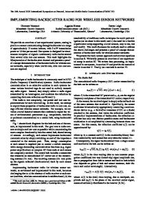
Introduction The health care market has become a four trillion dollar industry worldwide. Predictions estimate a doubling within ten years [Plu06]. With this enormous growth comes the need for new information technologies to achieve two critical goals: cutting costs while improving the quality of care. A long list of factors, including an intensely competitive health care market, strong pressure to prevent medical errors, and the need to comply with regulations, are combining to trigger rapid growth in technology spending. Interest in mobile monitoring technologies and electronic medical records is exploding as hospitals and clinics of all sizes strive to provide physicians and caregivers with advanced access to clinical information. Diagnosis, surveillance, and treatment are increasingly dependent on monitoring information. Sensors, such as shown in Fig. 1.1, transmit data to monitoring devices of the hospital IT infrastructure. Electrocardiogram (ECG), electroencephalography (EEG), body temperature, pulse oximetry (SpO2 ), and blood pressure are emerging as long-term monitoring sensors for emergency and risk patients. Advanced sensors for chemical, physical, and even visual applications will become part of future monitoring platforms to check, for example, insulin or hemoglobin. So far, most existing sensors are connected by wire to the medical monitors. The trend of future monitoring platforms is to replace the data cables between sensors and monitors by wireless links. Wireless technologies will provide much more freedom and mobility to the patients. The benefit to the 1
CHAPTER 1. INTRODUCTION
2 Blood pressure sensor ECG sensor
Medical monitoring infrastructure
SpO2 sensor Body temperature sensor
Figure 1.1: Sensor network of biomedical monitoring applications: Sensors transmit their recorded data wired or wireless to monitoring devices of the medical infrastructure. patient’s comfort is obvious, especially for long-term monitoring. In addition, complex monitoring during surgery and medical examination can be intensified, and information can be obtained during the patient’s activities and movements. Table 1.1 shows the data rate depending on the appropriate sampling rate of target biomedical sensor applications. A single sensor for the monitoring Table 1.1: Biomedical sensor applications for monitoring of vital functions [PSAM05]. Parameter Blood pressure ECG 1-point ECG 12-point EEG 1-channel EEG 192-channel Body temperature Pulse oximetry (SpO2 )
Sampling Frequency [Hz]
Data rate with 12-bit
60 250 250 200 200 0.1 300
1.44 kbit/s 6 kbit/s 72 kbit/s 4.8 kbit/s 921.6 kbit/s 2.4 bit/s 7.2 kbit/s
3 of biological signals generates a small data stream of a few kbit/s. The sampling frequencies of biomedical sensors are typical below 300 Hz due to the fact that biological signals oscillate at frequencies of a few Hz, e.g., heart beat, breathing. It takes a large array of sensors, e.g., EEG 192-channel recording, to increase the data rate up to hundreds of kbit/s. Specific challenges in a wireless sensor network for patient monitoring are: • The presence of the sensors shall not impede the patient. • The signal transmission shall not interfere with human body functions. Existing regulations must be strictly met. • Real-time requirements have to be met to handle emergency situations. • Every sensor shall function over a long period with a small battery. • A large number of sensor nodes must be handled without mutual influence. • A sensor shall be placed on-body (band-aid), subcutaneous, or implanted (pill). Standard wireless technologies, well-known from wireless communication by portable computers, personal digital assistants (PDAs), and multimedia capable phones have been investigated for medical sensor networks. A link data rate of 64 kbit/s and low-power operation are desired. Low carrier frequency and low transmission power limit the local effects in human tissue, e.g., heating and tissue irritation. Table 1.2 compares WLAN, Bluetooth, Zig-bee, and active RFID. WLAN and Bluetooth offer data rates above the required data rates listed in Tab. 1.1, whereas Zig-bee and active RFID feature low transmission power. For the interconnection of sensors with a network topology as depicted in Fig. 1.1, standard wireless technologies are conditionally suited. WLAN and Bluetooth modules emit excessive transmission power and dissipate an overly high power level for battery-powered sensors. Zig-bee and active RFID offer insufficient data rates. Only active RFIDs target high miniaturization and an extremely low carrier frequency suitable for biomedical applications.
CHAPTER 1. INTRODUCTION
4
Table 1.2: Characteristic data of wireless technologies: WLAN, Bluetooth, Zig-bee, RFID, and desired technology for body sensor networks. Technology WLAN Bluetooth Zig-bee Active RFID Intra-Body COM (desired)
Frequency
Data rate
Transmission power
Size
2.4/5.1 GHz 2.4 GHz 868 MHz 134 kHz 64 kbit/s
100 mW 10 mW 1 mW < 1 mW < 1 mW
PC card PCB module PCB module pill band-aid / pill
Therefore, a novel transmission technique is sought which focuses on transmission power below 1 mW, data rates of 64 kbit/s, and the possibility for miniaturization to integrate the transceiver modules into band-aids and implantable pills.
1.1. INTRA-BODY COMMUNICATION TECHNOLOGY
1.1
5
Intra-Body Communication Technology
Intra-Body Communication is a novel signal transmission using the human body as the transmission medium for electrical signals [Zim95]. Figure 1.2 shows the modified network organization for interconnecting the biomedical sensors. The data is not transfered directly from the biomedical sensors to the hospital infrastructure as in Fig. 1.1; the sensors send their data via a suitable low-power and low-rate intra-body communication link to the central link sensor (located on the body like all other sensors). Any of the sensors may act as a relay sensor between a sensor and the central link sensor if a direct connection is limited. An external wireless link enables the data exchange between the central link sensor and the external hospital infrastructure. That link may consist of a standard wireless technology, e.g., WLAN, with a high data rate. For this link, the power consumption is not an issue due to the fact that a relatively large power source can be provided for the dedicated central module.
Blood pressure sensor ECG sensor
Intra-body communication link Link sensor
SpO2 sensor Body temperature sensor
External wireless link
Medical monitoring infrastructure
Relay sensor
Intra-body Communication Network
Figure 1.2: Simplified overview of the intra-body communication network: Intra-body communication link between sensor and central link sensor. External wireless link to the remote medical monitoring infrastructure.
CHAPTER 1. INTRODUCTION
6
Implanted sensor
On-body sensor
Personal patient Patient monitor data record
Intra-body communication link
External wireless link
On-body sensor Implanted sensor
Link sensor
Hospital access point
Figure 1.3: Modern hospital monitoring network: Sensors record and transmit their data to monitoring devices. The sensors on or inside the body use intra-body communication techniques for data transmission to other sensors. Eventually, the data is transfered from one central link sensor to a hospital access point and can be analyzed on personal monitoring devices or stored in the patient’s electronic record.
The components of the modified network topology are shown in Fig. 1.3. Multiple sensors are distributed over the patient’s body to collect and transmit the biomedical data to monitoring units or data storage devices. The sensors are either attached on-body as band-aids or implanted as pills. Intra-body communication links will allow data exchange between two onbody sensors, two implanted sensors and even between on-body and implanted sensors. All sensor data are transmitted to and collected by the link sensors. The central link sensor is integrated into a wrist watch or other portable device and communicates to a hospital access point via a high-bandwidth wireless link. The patient’s data is monitored on personal patient monitors or stored in the patient’s electronic data record. Therefore, the monitoring
Sensor Data
Data Reduction
Symbol Encoding
Modulation
Digital Unit
Coupler Transmitter Unit
Coupler electrodes
Human Body
1.1. INTRA-BODY COMMUNICATION TECHNOLOGY
Demodulation
Symbol Decoding
7
Data Extraction
Data Monitor
Digital unit Detector Receiver Unit
Detector electrodes
Figure 1.4: Intra-body communication for data transmission between sensors enabled by transmitter and receiver units: The human body acts as the transmission medium. data is available anytime, online, and in real-time. The main components of an intra-body communication link are shown in Fig. 1.4. A transmitter unit allows sensor data to be compressed and encoded and transmits the data by a current-controlled coupler unit. The human body serves as the transmission channel. Electrical signals are coupled into the human tissue and distributed over multiple body regions. The receiver unit consists of an analog detector unit that amplifies the induced signal and digital entities for data demodulation, decoding, and data extraction. State-of-the-Art The novelty of intra-body communication is the usage of the human body as the transmission medium. The body becomes an integral component of the transmission system. Sophisticated transceivers enable electrical current induction into the human tissue and provide smart data transmission by advanced encoding and compression. Emerging body transmission systems1 have shown the feasibility of transmitting electrical signals through the human body. However, detailed characteristics of the human body are lacking so far. Unfortunately, not a lot is known about the influences of human tissue on electrical signal transmission. For advanced transceiver designs, the effects and limits of the tissue have to be carefully taken into consideration. 1 The
most advanced body transmission systems are presented and compared in Chapter 2
CHAPTER 1. INTRODUCTION
8 Regulations
Safety requirements for limiting exposure to time-varying electric, magnetic, and electromagnetic fields are enforced by national commissions, e.g., EU directives [Eur96, Eur99] and FCC [Fed85]. These regulations are based on international guidelines by the International Commission on Non-Ionizing Radiation Protection (ICNIRP) [Int97] and IEEE Standard for Safety Levels [C9506] combined with national considerations, e.g., [NRP04, PA02]. Table 1.3 summarizes threshold currents for indirect effects2 . In general, it has been shown that threshold currents, which produce perception and pain, vary little over the frequency range of 100 kHz and 1 MHz. Below 100 kHz the primary effect of alternating current is nerve and muscle stimulation perceived as a primary sensation of nerve tingling. At increased frequencies from 100 kHz to 10 MHz, the dominant effect changes towards heating, while above 10 MHz the limits are defined in terms of the specific absorption rate (SAR). Temperature rises of less than 1 degrees are considered to be safe, i.e., not resulting in any adverse heating effects. Table 1.3: Ranges for threshold currents for indirect effects, including children, women and men [Int97]. Indirect Effect Touch Perception Pain on finger contact Painful shock Severe shock difficulty
Threshold current [mA] 50/60 Hz 1 kHz 100 kHz 1 MHz 0.2-0.4 0.9-1.8 8-16 12-23
0.4-0.8 1.6-3.3 12-24 21-41
25-40 33-55 112-224 160-320
24-40 28-50 n/a n/a
Derived from the guidelines, intra-body communication is restricted by the limits of contact currents [Int03]. Depending on the frequency range, the allowed contact current increases up to 20 mA at 100 kHz and remains constant above according to Tab. 1.4. The occupationally exposed population 2 Threshold
currents for indirect effects is a term used in the standard to express current limits triggering particular physical sensations of the subjects
1.1. INTRA-BODY COMMUNICATION TECHNOLOGY
9
Table 1.4: Reference levels for time varying contact currents from conductive objects [Int97]. Exposure Characteristics
Frequency Range
Max. Contact Current [mA]
Occupational Exposure
2.5 kHz - 100 kHz 100 kHz - 110 MHz
0:4 � f [kHz] 40
General Public Exposure
2.5 kHz - 100 kHz 100 kHz - 110 MHz
0:2 � f [kHz] 20
consists of professionals who are exposed under known conditions. These people are trained to be aware of potential risks and to take appropriate precautions. In contrast, the general public comprises individuals of all ages and of varying health status, and may include particularly susceptible groups or individuals. Since the threshold currents that elicit biological responses in children and adult women are approximately one-half and two-thirds, respectively, of those in adult men, the reference levels for contact currents for the general public are set to half the values for occupational exposure. For the purposes of the clinical trial and type approval, this project followed the Swiss regulations [Sch00, Ber01, Bun94]. All irritation, heating, and destruction of human tissue has to be limited in compliance with these regulations.
CHAPTER 1. INTRODUCTION
10
1.2 Contributions The goal of this thesis is to explore the human body as a transmission medium of electrical signals. For this purpose, the dielectric properties of human tissue have been analyzed, models of the body as a transmission channel have been developed, and suitable transceiver architectures have been proposed. Specifically, the contributions to the intra-body communication architecture are as follows: • Based on cell models and reports on conductivity and permittivity of dedicated tissue, layered tissue models of discrete components and numerical finite-element models have been developed, simulated, and compared with specific tissue components and extended geometries. The results allow the electrical characterization of the body and give explanations of the transmission behavior of the body parts [WLF+ 05a, WOKF06]. • A dedicated measurement setup has been developed for in vivo verification of the simulation results [WLF+ 05b]. The measurement system allows the coupling of alternating current by differential electrodes in human tissue and measurement of the potential differences at other body locations [WOF+ 06a]. The feasibility of intra-body communication has been demonstrated and the technology has been explored in a clinical trial among a group of 20 subjects. • Advanced transceiver architectures have been implemented for coupling signal current into and inside the human body. The implementation of the digital units for on-body transceivers [WFOK06] and a test system for implant communication including four transmitters and one receiver are presented [WHK+ 07]. • The first silicon implementation of the modified SPIHT algorithm achieves compression ratios of up to 20:1 for ECG signals. The compressed data still contains all significant details for medical diagnosis [WPB+ 06]. In summary, this thesis attempts for the first time to model and simulate the human body as a communication channel and proposes suitable on-body and implantable transceiver architectures for intra-body communication.
1.3. OUTLINE OF THE THESIS
1.3
11
Outline of the Thesis
Chapter 2 explores the existing intra-body communication approaches. Capacitive and galvanic coupling are presented as the two most advanced body transmission principles. Chapter 3 introduces models for the intra-body communication channel. Based on the relative permittivity and conductivity of the different tissue layers, electrically equivalent circuits and simulation models are developed in order to simulate the human body as a signal transmission medium. Chapter 4 presents a dedicated measurement setup for in vivo verification of the simulation results. Initial feasibility measurements are conducted and different electrodes are compared. Chapter 5 summarizes the results of a clinical trial. With the developed measurement system, galvanic coupling is explored and the relations between individual-specific body parameters and electrical signal transmission are concluded. Chapter 6 presents the implementation of an intra-body communication system for sensor applications. The proposed architecture describes all building blocks of the digital transceiver and the analog front-end. The implementation focuses on future integration into a mixed signal full custom ASIC. Chapters 7 and 8 give application examples of the novel technology. Chapter 7 shows the adaption of the technology to wireless implants while Chapter 8 reports on an on-body ECG monitoring application that makes use of data compression. Finally, a summary is presented and conclusions are drawn in Chapter 9. The acronyms used are summarized in an appended glossary.
Chapter 2
Body Transmission Systems The fact that electricity can interact with biological processes has been known for more than 2,000 years. The electrical discharge of the torpedo fish was reported to have been used as early as 46 A.D. to treat pain [Rei98]. The beginnings of quantitative bioelectrical science can arguably be ascribed to the investigations of Galvani (around 1790) and later of Volta and Faraday (around 1831). Galvani observed motion in frogs’ legs when he touched them with metallic wires. That encouraged further investigations of electrical stimulation. Biological investigations by Faraday demonstrated that interrupted electric current was an effective means of electrical stimulation of nerves. The term Voltaic stimulation is used to indicate direct current stimulation, and Faradaic to indicate pulsed or interrupted stimulation. Nowadays, the most rapidly growing area of electrical stimulation is in biomedical technology. Electrical stimulation has increasingly been used as a tool for medical diagnosis, therapy, and prosthesis [LOW+ 03]. Furthermore, electrical stimulation is investigated by attempts to detect the provoked potential differences in other body parts. The signal transmission is deliberately based on the possibility to detect these signals. In conclusion, body transmission networks deploy sensor communication that is uniquely based on the body proximity. In contrast to standard wireless technologies, body transmission systems benefit directly from the presence of the human body. 13
CHAPTER 2. BODY TRANSMISSION SYSTEMS
14
Table 2.1: Body transmission systems based on capacitive and galvanic coupling comparing the coupling amplitude, carrier frequency, modulation method, and the achieved data rate. Coupling method
Coupling amplitude
Fukumoto [FT97] capacitive Zimmerman [Zim95] capacitive Reynolds [PRG+ 97] capacitive Partridge [PDV+ 01] capacitive Fujii/Ito [FIT02] capacitive + Hachisuka [HNT 03] capacitive NTT/Docomo [FSS03]capacitive
21 V 30 V 10 V 22 V 3V 1V 25 V
Lindsey [LMHH98] Handa [HSI+ 97] Oberle [Obe02]
3 mA 20 µA 4 mA
galvanic galvanic galvanic
Carrier Encoding frequency 90 kHz FM 330 kHz OOK 70 kHz FSK 160 kHz FSK 10 MHz OOK 10.7 MHz FSK 10 MHz OOK 37 kHz FM 70 kHz PWM 60 kHz CPFSK
Data rate [bit/s] 0.1 k 2.4 k 9.6 k 38.4 k n/a 9.6 k 10 M n/a 0.9 k 4.8 k
Several attempts were made to send and receive electrical signals over the human body. Two general methods have been developed: • Capacitive coupling • Galvanic coupling The human body is used as a signal transmission medium through both of these body transmission principles. The differences between the two methods lie in the signal coupling. The induced electrical signal is either controlled by an electrical potential or by a current flow. In the following, the most important findings on body transmission are introduced by the developed systems indicated in Tab 2.1. The differences can be related to the coupling method, the coupling amplitude, the chosen frequency range, the signal modulation method, and the application-specific data rates.
2.1. CAPACITIVE COUPLING BODY TRANSMISSION
2.1
15
Capacitive Coupling Body Transmission
The first successful system was reported by Thomas G. Zimmerman [Zim95] and was known as the Personal Area Network (PAN). The researchers at MIT’s media lab discovered that capacitive coupling of the human body to its environment and certain parts of the near field could be exploited to make the human body act as a medium for data transmission. Figure 2.1 depicts a model of the electric near-field produced by a PAN transmitter in body proximity. The PAN transceiver is composed of a transmitter and a receiver unit, each with two electrode plates. The electric field Ea , induced by a signal electrode of the PAN transmitter, passes through the body and flows toward ground. The goal is for the receiver unit to detect the electric field Es . The field Es is extremely small because a significant part of the electric field Ea is canceled by the electric field Eb established toward the ground electrode
Figure 2.1: Electrical fields produced by PAN transmitter [Zim95]: A small portion of the electric field induced by the transmitter reaches the receiver.
CHAPTER 2. BODY TRANSMISSION SYSTEMS
16
of the transmitter. In addition, a major part of the electric field Ec escapes through the feet, which are in direct contact with the ground. The return transmission path is established by the second plate of each unit via ground. According to Zimmerman [Zim96], near-field communication can operate at very low frequencies and low transmission power. The prototype of the PAN transmitter operates at 330 kHz, 30 V, with a transmission power consumption of 1.5 mW for charging the electrode capacitance. The PAN technology was proposed for integration into a custom CMOS chip to achieve lower size and cost. A demonstrator system allowed the modest transmission of 2.4 kbit/s. Digital information has been encoded using on-off keying with quadrature detection to reduce stray interference and increase the receiver sensitivity. Several interesting applications have been proposed [ZSP+ 95]. The potential of this technology lies in identification and biomedical applications.
Information
Encoder Transmitter Unit
Coupler
Human Body
The principle of Zimmerman’s PAN system has served as a reference for further capacitive coupling body transmission. The main components and the application to the body can be identified as depicted in Fig. 2.2: a transmitter unit consists of an encoder for data modulation and a coupler unit. One of the two coupler electrodes connects to the body, while the other conducts ground. At the receiver side, the detector records the signal as a potential difference between the two detector electrodes; one is connected to the body and the other to ground. A subsequent decoder demodulates the transmitted signal.
Detector
Decoder
Information
Receiver Unit
Earth Ground
Figure 2.2: Capacitive coupling for data transmission between transmitter and receiver units: One signal path is established through the human body while the return path has to be connected by earth ground.
2.1. CAPACITIVE COUPLING BODY TRANSMISSION
17
Further systems have been developed with different coding schemes and coupling parameters. The physical limits of intra-body signaling was explored by Gray [Gra97]. The channel capacity analysis revealed that the noise present in PAN devices is dominated by amplifier noise and external interference. Furthermore, it was attempted to increment the baud rate from 300 to several kbaud. The prototype uses on-off keying (OOK) as well as differential binary phase shift keying (BPSK). A final hardware design, led by Matthew Reynolds [PRG+ 97], reached a speed of 9600 baud employing a phase-locked- loop (PLL) for analog demodulation and implemented frequency shift keying (FSK). K. Partridge et al. [PDV+ 01] presented an improved system operating up to 38.4 kbit/s. The carrier frequencies were chosen at 180 kHz and 140 kHz for FSK modulation. In addition, a tunable amplitude level of up to 22 V was implemented. Experiments show that the plate size and shape have only minor effects, but that the distance of the body to the transceiver plate significantly effects the signal strength. Furthermore, the signal attenuation of devices with poor ground coupling particularly suffer. Direct coupling by Masaaki Fukumoto et al. [FS94, FT97] is a modified version of the basic capacitive method. Ring-shaped FingeRing transmitters are worn on each finger and used for command and data input by finger-tip typing action. The receiver unit is worn on the human arm. Thus, the return path is not coupled through ground but the air only. The system operates by analog frequency modulation at frequencies within 50 kHz to 90 kHz for transmitting a simple protocol of ID numbers. Katsuyaki Fujii and Koichi Ito [FIT02] presented a wearable ID key that allows users to personalize a receiver device by simple touch. Data is transferred via the body by a network module called TouchNet. They studied the receiving level in relation with the electrode locations of their wearable devices [FIT03]. Little is known about the transmission mechanisms of such devices in the physical layer. Therefore, a simulation model of the transmitter and the receiver attached to the arm has been proposed using the FiniteDifference Time-Domain (FDTD) method. Based on this model, the difference in the received signal levels was estimated under various conditions of the transmitter and receiver electrode structure. The size of the electrodes is detected as one of the key issues. It has been discovered in these simulations that a ground electrode close to the transmit electrode strengthens the
18
CHAPTER 2. BODY TRANSMISSION SYSTEMS
generated electric field, while the presence of a ground electrode close to the receiver electrode reduces the received signal level [FI04]. The intra-body communication devices proposed by Keisuke Hachisuka et al. [HNT+ 03] realized digital data transmission at 9.6 kbit/s using an FSK transmitter and receiver devices. The carrier frequency of 10.7 MHz is the intermediate frequency of FM radio receivers, meaning that the proposed system can make use of a wide selection of inexpensive commercial radio frequency devices [HTK+ 05, HTT+ 05]. Two Japanese telecommunication companies, Nippon Telegraph & Telephone Corp. and its subsidiary NTT DoCoMo Inc., have developed a technology that turns the human body into a broadband link. The technology uses the body’s conductivity and allows the exchange of data between personal digital assistants (PDA) by human touch [FSS03]. The intra-body communication system is enabled by electro-optic probes [SFOK04]. The electric field passed through the electro-optic crystal is detected as changes in the polarization of a laser beam [FSS03]. The electro-optic sensor features a high input impedance, high-sensitivity and high-speed operation capability. A data rate up to 10 Mbit/s is claimed. The method of capacitive coupling has several weak points: • The return path of the signal has to be guided. In the presented systems, the conduction with ground is a must for whole-body transmission. • The dominant signal transmission channel is not inside the body but on the surface of the arm, because the signal is distributed as a surface wave. • The capacitive plates themselves are likely to emit stray fields. • Transmission by radiation through air becomes increasingly relevant the higher the carrier frequency is increased. In conclusion, capacitive coupling is highly dependent on the environment. Galvanic coupling, as presented in the next section, reduces this dependency.
2.2. GALVANIC COUPLING BODY TRANSMISSION
2.2
19
Galvanic Coupling Body Transmission
Galvanic coupling follows the approach of coupling alternating current into the human body. A simplified presentation of the method is shown in Fig. 2.3. The two electrodes of the coupler and the two electrodes of the detector are coupled to the human body. Therefore, ground is not required for reference as in the method of capacitive coupling (Fig. 2.1). The signal is applied differentially over the two coupler electrodes. A primary current flow between the coupler electrodes is established and a small secondary current propagates further into the conductive body parts. The induced current results in an alternating potential difference between the detector electrodes. In this case, ionic fluid within the human body, rather than electro-magnetic waves in free space, is the carrier of the information. In comparison with capacitive coupling (Fig. 2.2), galvanic coupling feeds alternating current into the human tissue as shown in Fig 2.4 with the aid of two electrodes. The functional blocks of the transmitter unit, encoder and coupler, are adapted to the current-controlled signal transmission. The same applies to the receiver unit, consisting of detector and decoder. Secondary current flow
UCoupler
Primary current flow
Coupler electrodes
Conductive tissue
UDetector
Detector electrodes
Figure 2.3: Concept of galvanic coupling: The applied alternating current establishes a current flow between the coupler electrodes; a secondary current flow propagates further into the conductive body parts and can be detected as a potential difference between the detector electrodes.
Information
Encoder Transmitter Unit
Coupler
Human Body
CHAPTER 2. BODY TRANSMISSION SYSTEMS
20
Detector
Decoder
Information
Receiver Unit
Figure 2.4: Data transmission by galvanic coupling between transmitter and receiver units: Differential current is coupled into the human body by the pair of coupler electrodes and sensed by the pair of detector electrodes. A small number of prototypes have been developed using this galvanic coupling method for signal transmission through human tissue. A low-power consumption wireless system for ECG monitoring has been proposed by Takashi Handa et al. [HSI+ 97]. It consists of an ECG detector located on the chest and a relay transmitter placed at the wrist. Between the detector unit and relay transmitter, the signal is sent as an alternating 20 µA current flow through the body tissue. The system can be driven by a very small power source, since this implementation achieves a very lowpower signal transmission of 8 µW. The pulse-width modulator frequency is 900 Hz, and the carrier frequency is 70 kHz. The goal of Derek P. Lindsey et al. [LMHH98] was to reduce the space requirements for implant electronics in in vivo telemetry applications. A new data transmission method was developed and tested that utilizes the ionic properties of body fluids as the transmission medium. Motivated by an application using the new method to transmit information from a sensor which measures tension in anterior cruciate ligament grafts, a sine wave was injected into a cadaver leg using platinum electrodes implanted into the lateral femoral epicondyle. The signal was detected by electromyogram (EMG) surface electrodes. For the proposed applications, a current of 3 mA was injected at a frequency of 37 kHz. Joe Schulmann [SMW+ 06] describes the BION, a broadly applicable platform technology for minimally-invasive neural stimulation. The prototype is designed to send bi-directional messages on a 5 MHz wide radio channel with a transmission current of 3 mA. The injectable stimulator, in the form
2.3. DISCUSSION
21
of a BION implant, enables a multi-channel battery-powered communication sensor. Michael Oberle [Obe02] presented a design and the implementation of a low-power biomedical communication approach. The system describes a signal transmission based on the dielectric characteristics of human tissue. This galvanic coupling approach implements continuous phase frequency shift keying (CPFSK). By preventing abrupt changes at the bit transition instants, this leads to improved spectral efficiency and rapid spectral rolloff. The symbols are encoded at the frequencies of 51.2 kHz and 61.4 kHz.
2.3
Discussion
In conclusion, the survey of existing solutions using the conductivity of human tissue shows a broad range of approaches. Even if some attempts may sound like science fiction, it is possible to propagate electrical signals through the human body. • Capacitive coupling has been implemented in several approaches. The data rate has been increased up to 10 Mbit/s. However, the drawback of a reference ground has always remained. • Galvanic coupling omits the weak points of capacitive coupling. The transmission is no longer dependent on a return path by earth grounding due to the fact that the current propagation takes place only within human tissue. The presented galvanic approaches feature only low data rates that have not reached the desired transmission speed of the proposed sensor network. Therefore, more sophisticated transceivers shall enable higher data rates using the human body channel more efficiently. So far, none of the presented works has investigated human body properties nor carried out a model of the human body as a transmission medium. The method of galvanic coupling has been proposed without detailed studies on the signal transmission and the biological processes occurring in the human tissue. However, it is of particular interest which human tissue layers are involved the most and what the biological limitations of the transmission method are. Therefore, tissue models are required and appropriate simulations shall investigate the signal propagation through the human body.
Chapter 3
Channel Models of the Human Body Intra-body communication denotes the technology of signal transmission through the body for on-body and implanted sensor communication. Electrical signals are transmitted by the galvanic coupling of alternating currents in the milliampere range. Thus, the human body becomes the transmission channel of the communication system. A profound understanding of its channel characteristics and a simulation model are required for defining the channel constraints and the subsequent system constraints of a transceiver design. The most crucial questions are: • Which tissue layers contribute to the current flow most? • How large are the differences in transmission characteristics among the different parts of the body? • What body constitution and fat/muscle/fluid combination best supports the signal transmission? • To what extent do electrode type and size variations influence transmission? These points shall be targeted through the investigation of equivalent circuit models based on the dielectric properties of human tissue. 23
24
CHAPTER 3. CHANNEL MODELS OF THE HUMAN BODY
Figure 3.1 schematically depicts the human arm and the setup of galvanic coupling. The three tissue layers, skin, muscle and bone, build a highly simplified model. In order to investigate the tissue parameters and equivalent electrical impedances, an alternating current generated in the coupler unit is injected between the two coupler electrodes. The detector unit senses the transmitted signal through the two detector electrodes. The attenuation factor between the coupler and the detector electrodes was calculated using Attenuation[dB] = 20 � log10
�
UDetector UCoupler
�
(3.1)
where UCoupler denotes the voltage between the coupler electrodes and UDetector the voltage at the detector electrodes. In this chapter, the channel models of intra-body communication are introduced. Transmission based on galvanic coupling is compared to the electrical stimulation of human tissue in Sec. 3.1. Section 3.2 shows an analytical model of the transmission channel. In Sec. 3.3, the modular models of the human body are developed, based on cell behavior when exposed to electrical stimulation and on the dielectric properties of different tissue layers. Section 3.4 combines the human body and the coupling method in a simple body model, leading to the layered structure of human tissue in Sec. 3.5. In Sec. 3.6, finite-element models allow the simulation of more advanced body geometries starting with the human arm. Detector Coupler U Detector U Coupler Detector electrode Coupler electrode
Bone
Human Arm
Muscle Skin
Figure 3.1: Simplified view of a human arm with the three tissue-layers skin, muscle, and bone.
3.1. EXISTING ELECTRICAL STIMULATION OF TISSUE
3.1
25
Existing Electrical Stimulation of Tissue
The setup shown in Fig. 3.1 is quite similar to the approach of electrical impedance tomography (EIT) and comparable to functional electrical stimulation (FES). These methods make use of the electrical conductivity of human tissue for diagnostics and treatments. According to Tab. 3.1, DC and low alternating currents of a few mA are applied. Electrical Control of Biological Mechanisms In functional electrical stimulation (FES), biological mechanisms are influenced or explicitly triggered by externally applied currents. The study of electrical body signals produced by biological processes shows that their power spectrum mainly covers the low frequency range. For example, currents generated by the heart have a power density spectrum that lies mainly below 1 kHz, while most other electro-physiologic sources (e.g. those underlying the EEG, EMG, EOG) are of even lower frequencies. Models were used to find the parameters that have the highest influence on nerve activation during stimulation [KK06]. Resistivity Visualization for Medical Diagnosis Electrical impedance tomography (EIT) attempts to image the internal organs and structure of the body by measuring tissue resistivity [HJ78]. A typical EIT system places multiple electrode pairs around the body (e.g. 24 electrodes), applies a constant current to one electrode pair (coupler), and records the potential at the remaining electrodes (detectors). The potential arises from the tissue impedance between two electrodes. Sets of impedance measurements are collected for every single electrode pair. These impedance Table 3.1: Biomedical applications coupling electrical currents to the body. Type / Purpose Electrical stimulation Impedance tomography Impedance analysis Intra-body communication
Frequency
Current
below 1 kHz DC DC - 500 kHz 10 kHz - 1 MHz
µA up to 0.9 A 4 mA 0.5 - 4 mA 1 mA
26
CHAPTER 3. CHANNEL MODELS OF THE HUMAN BODY 0.038
Front 0.036
0.034
Left
0.032
0.030
0.028
0.026
Figure 3.2: A time averaged EIT image of a cross section of a human chest [KML01]. data are used to reconstruct the tissue impedance distribution in the volume between the electrodes. This allows a low-resolution image of the body organs and tissue to be derived as shown in Fig. 3.2. The cross-sectional image of the distribution of conductivity shows the body structure by assuming differences in conductivities of human tissue in the range from 1.54 S/m for cerebrospinal fluid to 6 mS/m for bone. Despite the fact that the goal of intra-body communication is quite different, there are several analogies between these approaches. In electrical impedance tomography (EIT) currents are injected with the goal to detect the impedance distribution of human tissues [BB84, PL02, SBN+ 01, SGS95]. In functional electrical stimulation (FES) models were used to find the parameters that have the largest influence on nerve activation during stimulation [KK05]. In order to investigate the body parameters, several dielectric models have been developed. While EIT targets higher resolution and FES explores the effects on the human nerves, intra-body communication primarily searches for a low attenuation of the transmitted signals. Furthermore, intra-body communication not only focuses on the tissue impedances at constant currents but also for time-varying currents. The desired body models shall give explanations at the frequency range up to 1 MHz. Therefore, the parametric models of the dielectric properties of human tissue have to be extended over the dedicated range.
3.2. ANALYTICAL CHANNEL MODEL
3.2
27
Analytical Channel Model
In order to identify the major influences to the transmission channel, an analytical model is drawn in Fig. 3.3. The coupling behavior, the body conditions, and external noise sources are modeled. • Both the coupler and the detector electrodes attenuate the transmitted signal. • The dielectric tissue parameters define the attenuation behavior of the human body. The tissue models shall provide better explanations on the attenuation dependency of the tissue properties and the general geometry setup, e.g., distance and structure. The clinical trial will investigate the subject-specific body properties, e.g., defined by extracellular and intra-cellular water content. • Additive in-band noise is caused by external devices, especially other wireless communication units, e.g., RFID. • Human body noise is approximated by additive white noise. Body properties
White noise
Input signal
Output signal Electrode coupling
In-band noise
Electrode coupling
Figure 3.3: Analytical model of the body communication channel: The transmitted signal is attenuated by the coupling electrodes, filtered based on inter-cellular and extra-cellular water distribution and added with noise caused by body effects and other in-band noise sources.
28
CHAPTER 3. CHANNEL MODELS OF THE HUMAN BODY
3.3 Dielectric Properties of the Human Tissue In order to understand the pathway of electrical current flow through the human body, the tissue has to be characterized in terms of its dielectric constants. The findings from measurements shall serve as the basis for a parametric model of the dielectric properties. Derived equivalent circuits shall build the starting point for layered tissue models. Experimental Findings on the Dielectric Properties The conductivity of human tissue is based on the cell properties. Cells are membrane bounded compartments filled with a solution of certain chemicals and salt concentration. Groups of cells perform specialized functions and are linked by an intricate communication system. The cell membrane maintains an ion concentration gradient between the intra-cellular and extracellular spaces. This gradient creates an electrical potential difference across the membrane which is essential to cell survival. Electrical gradients are necessary to support the transport of oxygen, carbon, dioxide, and nutrients. Therefore, the cell membrane has electrically insulating qualities to maintain the electrical gradient. Biologically, the cell membrane functions as a permeable barrier separating the intra-cellular (cytoplasm) and extracellular components [Bro06]. The specific resistances of various body tissues have been measured by Schwan [Sch57]. The results showed that the resistivity decreases slowly as the frequency increases up to 10 kHz. Foster et al. [FS89] review the dielectric phenomena in biological materials and their interpretation in terms of interactions at the cellular level. Barber & Brown [BB84] presented a survey on the conductivity values of mammalian tissues comparing results at 100 kHz. The human arm showed a conductivity of 0.42 S/m longitudinal, 0.15 S/m transverse. Lung tissue ranges from 0.14 S/m to 42 mS/m during expiration and inspiration, respectively. Blood is reported to have a conductivity of 0.66 S/m, and the conductivity of fat is 40 mS/m. The lowest conductivity is reported for wet bovine bone with 6.02 mS/m. Although the reported conductivity values for any tissue might vary considerably, it is expected that the bulk resistivity of the human tissue is in the order of ten Ωm. The most profound overview of the relative permittivity and conductivity
3.3. DIELECTRIC PROPERTIES OF THE HUMAN TISSUE
29
of tissue was published by Gabriel et al.. In [GLG96b], the current state of knowledge in terms of dielectric tissue properties over ten frequency decades was assessed. Measurements in the frequency range from 10 Hz to 20 GHz provide the basis for the evaluation and analysis of the mammalian tissues. Nevertheless, the results are based on homogenized animal tissue. Differences between living and dead human tissues are to be expected. In [GLG96a], the measured values of the relative permittivity and conductivity were presented. The relative permittivity decreases from values in the range of 105 at a few hundred Hz to less than 100 in the GHz range, whereas the conductivity increases starting around 10 4 S/m to above 1 S/m in the same frequency range. The electrical properties of tissue and cell suspensions change with frequency in three distinct steps termed as α, β and γ dispersions: • α dispersion in the frequency region below 1 kHz is associated with ionic diffusion processes on both sides of the cellular membrane and with the polarization of ions near charged surfaces in the tissue. The relative permittivity reaches values of more than 105 . • β dispersion, in the range of 100 kHz to 10 MHz, is due mainly to the polarization of cell membranes which act as barriers to the flow of ions between the intra- and extra-cellular media. • γ dispersion in the gigahertz region is due to the polarization of water molecules. The conditions and the physics of the tissue material vary over time. Nonetheless, as a first approximation, the involved tissue layers can be parameterized by their dielectric constants, which are material- and frequencydependent. Parametric Model of the Dielectric Tissue Properties As seen in the section above, the dielectric tissue, represented by the relative permittivity εr and the conductivity σ, is characterized by the three main relaxation regions α, β and γ at low, medium and high frequencies. In their simplest forms, each of these relaxation regions is caused by a polarization mechanism characterized by a single time constant τ. The Cole-Cole
CHAPTER 3. CHANNEL MODELS OF THE HUMAN BODY
30
equation [CC41] formulates this as a first approximation with ε� (ω) = ε∞ +
∆εn 1 + ( jωτn )(1
αn )
:
(3.2)
It contains a frequency independent part, which is due to ionic conduction, and a frequency-dependent part based on dielectric relaxation. Each dispersion region is broadened depending on the composition of the biological material by introducing the distribution parameter α. In addition, the decrease in the three distinct dispersion regions is described by the summation of multiple Cole-Cole equations. For multiple contributions, the frequencydependent permittivity then is ε� (ω) = ε∞ + ∑ n
ε� (ω) αn τ ε0 ε∞ εs ∆ε = εs σi
ε∞
∆εn 1 + ( jωτn )(1
αn )
+
σi : jωε0
(3.3)
complex relative permittivity distribution parameter relaxation time constant permittivity of free space permittivity at frequencies ωτ � 1 permittivity at frequencies ωτ � 1 magnitude of the dispersion static ionic conductivity
The relaxation time constant τ depends on physical processes: τ in the range of • picoseconds indicates a reorientation of molecular dipoles • seconds is due to ion effects Equation 3.3 can be used to predict the dielectric behavior over the desired frequency range. The corresponding equation for the tissue conductivity can be derived from the general relation between conductivity and permittivity [εs
σ∞ σs
ε∞ ] � ε0 τ
= σ∞
conductivity at frequencies ωτ � 1 static conductivity
σs
(3.4)
3.3. DIELECTRIC PROPERTIES OF THE HUMAN TISSUE
31
The complex conductivity σ� and the complex specific impedance z� of the tissue are σ�
=
jωε0 ε� = σ∞ + ωε0 ε∞ +
z�
=
1 σ�
σs σ∞ 1 + jωτ
(3.5) (3.6)
The dielectric properties are defined based on Eq. 3.3 and parameter estimations for αn , τn , ∆εn , σi , and ε∞ by [GLG96c]. The simulation results in Fig. 3.4 show: • Up to a frequency of 10 MHz, the conductivity of muscle tissue is between 10 and 103 times higher than the conductivity of skin. • The conductivities of dry and wet skin differ by more than a factor of 100. This will have some influence on the expected change of attenuation by the human tissue. • The relative permittivity of muscle tissue is 103 times higher than the relative permittivity of dry skin up to 100 kHz, and the frequency behavior is similar to wet skin. For the common case of dry skin it 2
6
10
10
Dry skin Wet Skin Muscle Cortial Bone Fat
5
10
Conductivity [S/m]
Relative Permittivity
10
4
10
3
10
2
10
1
0
10
-1
10
-2
10
-3
10
-4
10
10
-5
10
0
10 3 10
Dry skin Wet Skin Muscle Cortial Bone Fat
1
4
10
5
10
6
10
7
10
Frequency [Hz]
8
10
9
10
10
10
3
10
4
10
5
10
6
10
7
10
8
10
9
10
10
10
Frequency [Hz]
Figure 3.4: Simulated relative permittivity and conductivity of wet skin, dry skin, muscle, bone and fat tissue calculated with the Cole-Cole equation Eq. 3.3 and the dielectric parameters from Gabriel [GLG96c].
32
CHAPTER 3. CHANNEL MODELS OF THE HUMAN BODY can be assumed that the muscle tissue will play the dominant role for signal transmission. • The conductivity increases rapidly above 10 MHz. Low impedances mean an increase in power consumption, since higher output currents will be necessary to drive the output signals between the electrodes. • The almost constant conductivities and permittivities for skin and muscle suggest good signal transmission between 100 kHz and 1 MHz.
Equivalent Tissue Models Dielectric properties are usually represented as a combination of capacitive and conductive elements. An equivalent circuit model can be derived knowing the dielectric parameters of a dedicated tissue. Figure 3.5 shows the equivalent circuit of Eq. 3.3 for a single time constant and α = 0.
ε - εs oo
ε
1 σi
τ (ε - εs )
oo
oo
Figure 3.5: Equivalent circuit that models the Cole-Cole equation for a single time constant τ and the distribution parameter α = 0. Figure 3.6a illustrates cell behavior under exposure to an alternating current. Applying a low-frequency voltage to the tissue will create a current, which flows mainly through the extra-cellular fluid since the impedance of the membrane is very large at low frequencies. At higher frequencies, current flows through the extra- and intra-cellular fluids. The equivalent circuit for a cell embedded in extra-cellular fluid is shown in Fig. 3.6b. Re models the extra-cellular fluid resistance, Ce models the current flow of the extra-cellular fluid as a function of the frequency. The
3.3. DIELECTRIC PROPERTIES OF THE HUMAN TISSUE high frequency current
33
low frequency cell membrane current
Rm
Cm Cm Re
Ri
extra-cellular fluid (a)
Ce
Re Ri
Ci
intra-cellular fluid (b)
(c)
Figure 3.6: (a) Tissues and current flow, (b) schematic diagram of the equivalent circuit of a cell, (c) simplified circuit. components of the cell membrane are represented by Rm and Cm , and those of the intra-cellular fluid by Ri and Ci . The equivalent circuit can be simplified in the frequency range of 1 kHz to 500 kHz. Figure 3.6c shows the simplified circuit, consisting of an extracellular resistive part Re in parallel with the capacitive Cm and resistive Ri components, representing the intra-cellular and the cell membrane contributions, respectively. In order to represent the significant tissue components, a body model will be assembled modularly composed of the corresponding electrical equivalent components.
34
CHAPTER 3. CHANNEL MODELS OF THE HUMAN BODY
3.4 Simple Discrete Body Model The goal of a simple discrete body model is the modeling of the main dependencies on the skin layer condition and the coupling electrodes. The simple model shall reduce the body complexity to its minimum and shall be compared later with more detailed approaches. Intra-body transmission can be described by a four-terminal circuit model with 10 impedances, as shown in Fig. 3.7 H
=
Zo (Zb Zt ) : 2 Zt Zb + Zo Zb + Zo Zt
(3.7)
This simple body model takes into account longitudinal transmit (Zt ), input (Zi ), and output impedances (Zo ) as well as cross impedances (Zb ) between the coupler and detector electrodes. The body impedances can be described in analogy to Fig. 3.6c as an equivalent circuit of the resistances Re and Ri and a capacitance Cm .
Zc
Coupler
Zi
Zt
Zb
Z c
Human Body
Zo
Detector
Zc
Z c
Zt
Figure 3.7: Simplified circuit model of the human body modeling the coupling electrode (Zc ), input (Zi ), and output (Zo ) impedances as well as longitudinal transmit impedances (Zt ) and butterfly cross impedances (Zb ).
3.5. LAYERED TISSUE MODEL
35
Rc
Cc
Figure 3.8: Equivalent circuit for electrode-skin contact: impedances Zc composed of Rc and Cc in a parallel circuit.
Coupling
The entire transfer function includes the coupling electrode impedances (Zc as a parallel circuit of Rc and Cc as shown in Fig. 3.8) 8