Gateway Cities: I‐710 ITS Infrastructure Report ‐ Final Report
Date: October 8, 2013
Prepared for: Gateway Cities Council of Governments
Los Angeles County Metropolitan Transportation Authority
Prepared by:
555 12th Street, Suite 1600 Oakland, CA 94607
20 California St, 7th Floor San Francisco, CA 94111
Table of Contents 1.0 Introduction ......................................................................................................... 1-2 2.0 Technical Terms .................................................................................................. 2-1 3.0 Connected Vehicle Infrastructure and Equipment ...................................... 3-1 3.1 DSRC Radio ................................................................................................. 3-3 3.2 DSRC Poles and Mounting Structures ..................................................... 3-5 3.3 DSRC Cabinet and Equipment ................................................................. 3-6 4.0 Automated Tolling Infrastructure and Equipment ...................................... 4-1 4.1 Toll Gantry and Toll Equipment .............................................................. 4-2 4.2 Toll Gantry Reader Cabinets and Equipment ........................................ 4-3 4.3 Toll Controller Cabinet and Equipment .................................................. 4-4 5.0 Changeable Message Sign Infrastructure and Equipment ......................... 5-1 5.1 Changeable Message Sign ......................................................................... 5-2 5.2 Changeable Message Sign Infrastructure ................................................ 5-5 5.3 CMS Cabinet and Equipment ................................................................... 5-6 6.0 Closed Circuit Television (CCTV) Infrastructure and Equipment ........... 6-1 6.1 CCTV Camera ............................................................................................. 6-2 6.2 CCTV Poles and Mounting Structures .................................................... 6-3 6.3 CCTV Camera Cabinet and Equipment .................................................. 6-5 7.0 Mainline Fiber Communication and Power Infrastructure ........................ 7-1 8.0 Summary .............................................................................................................. 8-1 9.0 List of Reference Materials ............................................................................... 9-1 Appendix A – Corridor Installation Map Appendix B – Typical Installation Figures Appendix C – Cost Estimates Appendix D – Sample Plan Sheets Appendix E – Caltrans Standard Plans
Gateway Cities Technology Plan for Goods Movement Technology Infrastructure Impacts
1.0 Introduction The purpose of this report is to present proposed technological equipment for Intelligent Transportation Systems (ITS), identify their functional specifications and their impact on infrastructure when applied to the Gateway Cities highways project on route I‐710 in Los Angeles County. The goal of the I‐710 zero emissions truck corridor (ZEFC) system is to operate all ZET in the corridor under automated coordinated operations (platooning), resulting in shortened headways between vehicles, increased reliability, and improved safety. The system will be a combination of vehicle‐to‐vehicle (V2V) and vehicle‐to‐infrastructure (V2I) connectivity through the application of advanced wireless technologies. Currently, this type of technology is being considered in a significant research effort headed by the U.S. DOT known as the Connected‐Vehicle program. Changeable message signs (CMS) may also be installed on the ZEFC. Closed Circuit Television (CCTV) installation may also be another technology deployed in the ZEFC. In Phase I of the Gateway Cities Council of Governments Strategic Transportation Plan a concept of operations and preliminary assessment of the anticipated technologies to be utilized on the corridor was outlined. Under this Phase II of work, more in‐depth impacts to the infrastructure are developed and evaluated. In particular, this study focuses on system requirements and the resultant impacts on the roadway, right‐of‐way, easements, operations and maintenance areas, and other items that would need to be taken into consideration in the future development of final design level documents. Field device systems considered include Connected Vehicle, Automated Tolling (independent of Connected Vehicle deployment), Changeable Message Signs (CMS) and Closed Circuit Television (CCTV). The infrastructure requirements for the Connected Vehicle system were developed with input from the USDOT’s Safety Pilot Model Deployment project which is occurring in Ann Arbor, Michigan (http://www.its.dot.gov/safety_pilot/). Automated Tolling is in accordance with several LA Metro’s ExpressLanes (FasTrak) projects. CMS and CCTV systems presented in this report are in accordance with Caltrans standards and specifications. The result of this review is to ascertain the impact of these technological installations on the transportation infrastructure. This analysis did not include vehicle detection technology since it is anticipated that connected vehicle technology could enact probe data for much more robust information. Also, third party, real‐time probe data has become so prevalent, cost effective, and reliable (nearly 95% as accurate as traditional detection) that it is also a much more viable solution. It should be noted that as technological research and development advances in connected vehicle and other ITS technologies, it is likely that some of the assumptions regarding equipment such as form factors, circuit board efficiency, or power consumption could result in very different impacts by the time this conceived system
1-1
Gateway Cities Technology Plan for Goods Movement Technology Infrastructure Impacts
will be built. Consequently, since this report is a snapshot in time, continued future research is needed to stay abreast with the evolution of these proposed solutions. Another technology component that will also be incorporated into these I‐710 corridors is automated truck enforcement. That information is included in the Truck Enforcement Network System (TENS). The TENS technology will be integrated into the I‐710 corridor technology plan. Finally, the information from the transportation technologies may likely be transmitted to a freight transportation information center (covered in a separate report).
Figure 1: ITS Combined Installation Site
Transpo Group
1-3
2.0 Technical Terms American Association of State and Highway Transportation Officials (AASHTO): A US organization that develops standards and guidelines for highway design and construction. Automated Tolling: Tolling done via wireless communication such that a “toll booth” is not used Automatic Vehicle Identification (AVI) Antenna: Used for detection of vehicle presence Power-over-Ethernet (POE): Power supply taken from Ethernet cabling California Department of Transportation (Caltrans): The statewide public agency that is responsible for managing the California highway system. California Highway Patrol (CHP): The law enforcement agency that is responsible for patrolling all California highways. Central Processing Unit (CPU): Computer hardware that is responsible for fulfilling commands from a computer program through the use of logic and algorithms. Changeable Message Sign (CMS): An electronic sign that is capable of dynamically adjusting the display message. Closed-Circuit Television (CCTV): The use of cameras which provide video transmission to a specific monitor location. Connected Vehicle: The USDOT’s program to use V2V and V2I to increase roadway safety and reliability Data Internet Protocol (IP) Data: The principal communications protocol for relaying data across networks Decibel (dB): Unit of measurement for power or intensity Dedicated Short Range Communication (DSRC): A wireless communication means that is regulated by the FCC, designed for automotive use on the 5.9GHz spectrum in the US. Digital Video Recorder (DVR): Electronic device that is used to record video in a digital format. Equivalent Isotropically Radiated Power (EIRP): A measure of signal power emitted by a roadside antenna unit Facility Management and Administration System (FMAS): A central location for managing roadway toll-related functions. Federal Communications Commission (FCC): A US government agency that is responsible for regulating wire and radio communications. Fiber Distribution Unit (FDU): Hardware used to terminate fiber optic strands High Occupancy Toll (HOT) Lanes: A lane designation that allows single-occupant vehicles to access the high-occupancy vehicle lanes by paying a toll High Occupancy Vehicle (HOV) Lanes: An exclusive lane that only vehicles with more than one occupant can utilize. Intelligent Transportation Systems (ITS): The use of advanced technology applications to improve safety and mobility in transportation networks.
2-1
Gateway Cities Technology Plan for Goods Movement Technology Infrastructure Impacts
Latency: Measurement of delay between network communications Local Patch Panel (LPP): Hardware used to terminate fiber optic strands Los Angeles Regional Transportation Management Center (LARTMC): A jointoperations facility between Caltrans and CHP that is used for emergency response efforts and freeway incident management for Los Angeles County and Ventura County freeways. National Electric Code (NEC): A national standard regulating the safe installation of electrical wiring and equipment in the United States. Traffic Operations Systems (TOS) Cabinet: A centralized hub location that consists of a cabinet that is used at major junctions for communication equipment. Traffic Management Center (TMC): A centralized facility with hardware and software to monitor traffic conditions and manage field devices Uninterruptable Power Supply (UPS): A back-up battery power supply that continues to energize devices in the event of power failures. United States Department of Transportation (USDOT): A federal department of the US government that is concerned with transportation. Vehicle to Infrastructure communication (V2I): The exchange of data between vehicles and roadside infrastructure Vehicle to Vehicle communication (V2V): The exchange of data between vehicles in a transportation network. Volts of Alternating Current (VAC) / Volts of Direct Current (VDC): Electrical charge that reverses in direction (VAC) or is unidirectional (VDC). ZET: Zero Emission Trucks ZEFC: Zero Emission Freight Corridor
2-2
Transpo Group
3.0 Connected Vehicle Infrastructure and Equipment The USDOT program for connected vehicle has a rich history of development that began in the early 2000’s. Connected vehicle analysis has included, among other efforts, white paper studies, proof of concept deployments, and piloted test sites. The proposed concept of operations for the zero‐emissions truck corridor has connected vehicle as one of the technological cornerstones of the envisioned facility. The use of connected vehicle applications is essential for improving safety, reducing environmental impacts, and optimizing the throughput of Zero Emission Trucks (ZET) in the Zero Emission Freight Corridor (ZEFC). The current national framework for the connected vehicle environment envisions the use of dedicated short range communication (DSRC), cellular (e.g. 3G, 4G, LTE), or potentially other types of radio communication between vehicles themselves and the surrounding infrastructure. While some of the anticipated applications for the zero‐ emissions truck corridor could conceivably utilize non‐DSRC communication to realize functionality, DSRC is the only option that would have specific impacts to the infrastructure. Consequently, DSRC is the focus of this analysis. DSRC has been established by the USDOT as a specifically allocated set of channels and frequencies for use in the anticipated connected vehicle world. It is also central to a continuing series of field evaluations and pilots being done by the USDOT. As of the writing of this report, the safety pilot test in Ann Arbor will help to inform a pending National Highway Traffic Safety Administration (NHTSA) decision that may impose the installation of DSRC in vehicles. Assuming that the upcoming NHTSA decision (anticipated Fall 2013) on this possible federal rulemaking results in a continuation of the program, a world with connected vehicle and DSRC is a high possibility. Recent estimates indicate that 20% of vehicles will be equipped with some form of connected vehicle technology by the year 2025. While other technologies could be considered to implement interconnectivity between trucks on the corridor, those that are conceived by the current USDOT sponsored connected vehicle program are the only ones that have an effort for national coordinated standards and non‐proprietary (open) solutions. In regards to freight vehicles traveling the corridor, on‐board communications equipment would be integrated with application equipment and processors that would implement several envisioned application packages. Much of the enabling technology for the autonomous system will reside in the truck itself and will include, ultimately, a wide variety of Original Equipment Manufacturer on‐board vehicle systems. This on‐ board equipment and technology will communicate with a variety of operation centers
3-1
Gateway Cities Technology Plan for Goods Movement Technology Infrastructure Impacts
and remotely situated application servers. The enabling architecture will likely utilize cellular and DSRC communication. While there has been draft development of a national connected vehicle framework and architecture, little has been done in the development of actual in‐vehicle applications for a connected vehicle system. There are many unknowns on the required data sets, bandwidth needs, latency requirements, and processing needs for connected vehicle applications. Despite these unknowns, we can make assumptions on the connected vehicle system that will allow us to envision the most impactful possibility. For the purposes of this analysis, we can then start off with the assumption that at least some of the proposed connected vehicle applications will require continuous DSRC coverage over the entire ZEFC. To enable this coverage, DSRC roadside installation sites would be implemented at regular intervals. It is anticipated that installation of these sites may need to begin as early as the on‐ramps and on some of the approaching arterials in order to provide the necessary environment for anticipated connected vehicle applications. The DSRC radio at each installation site would be capable of communicating with minimal latency over relatively short distances to ensure timely communication with all the ZETs on the corridor. For the purpose of this report, a dedicated DSRC infrastructure installation is conceptualized which includes a DSRC radio, pole, and cabinet. Additional infrastructure mounting options include existing light poles, possible catenary support structures, or signal pole standards. Control cabinets utilized for the ITS or tolling system can provide means to house necessary equipment for the connected vehicle system as well. While other systems and equipment will be necessary to realize the functionality of the envisioned connected vehicle system, such as “back room” servers, only the following equipment that have a direct impact on the I‐710 infrastructure were considered:
Connected Vehicle Equipment DSRC Radio DSRC Poles and Mounting Structures DSRC Cabinet and Equipment Communications and power conduit and cabling Splice vaults and pull boxes DSRC Installation Site Splice Vault DSRC Radio
DSRC Pole or Mounting Structure
DSRC Cabinet and Equipment Power Pull Box
3-2
Backhaul (Fiber or Wireless)
Power Drop
Traffic Management Center
Connected Vehicle Servers
Transpo Group
Gateway Cities Technology Plan for Goods Movement Technology Infrastructure Impacts
Appendix A outlines installation locations along the entire corridor. Appendix B provides visualizations of the following: DSRC Installation Plan and Elevation for an Elevated Structure DSRC Installation Plan and Elevation for At‐Grade Roadway Pole and Mounting Details Appendix C contains a cost estimate breakdown of all ITS installations. The proposed CCTV System Installation Estimate is summarized below:
Total Cost per Subtotal Cost Installation 23 $50,250.00 $1,155,750.00 4 $62,260.00 $249,040.00 22 $8,520.00 $187,440.00 $1,592,230.00
Total Sites DSRC SYSTEM: Elevated Structure DSRC SYSTEM: At‐Grade Installation DSRC SYSTEM: Combined with CCTV TOTAL DSRC SYSTEM
3.1
DSRC RADIO The DSRC radio device used in USDOT’s Safety Pilot Model Deployment project has a main body that is 8" (L) x 8 1/2"(H) x 2 3/4" (D) and weighs roughly 11 pounds. The ruggedized enclosure can withstand long exposure to temperature ranges from ‐30°F to +165°F and can operate during periods of extreme weather including rain, snow and wind. DSRC radios come equipped with two external omni‐directional antennas. An external LED indicator indicates the operational status of the device and provides visual feedback when the device is not operating correctly. Typically DSRC radios are equipped with GPS to enable applications that are location‐based.
DSRC Radio Installation The DSRC radio shall be mounted at a maximum height of 25 feet above the roadway bed surface before a maximum EIRP (Equivalent Isotropically Radiated Power) limitation occurs. If absolutely necessary, a height of up to 45 feet is acceptable, as long as the EIRP requirements in Section 90.377 of the Federal Communications Commission’s Intelligent Transportation Systems Radio Service are met. This means that a lower powered signal may be utilized if a higher site is needed to maintain “line of sight” with vehicles. A height of 25 feet provides approximately 1000 foot radius wireless communication range with an acceptable 10% data packet loss. Radios installed shall not interfere with other radios currently in place such that the difference in strength between the two is greater than or equal to 18 dB. This prevents signal overlap with nearby radios.
Transpo Group
3-3
Gateway Cities Technology Plan for Goods Movement Technology Infrastructure Impacts
The DSRC radio shall have an attachment method that allows for ease of installation and removal with common hand tools. This is required in order to provide ease of installation for the owner. Pole mounting is accomplished by the use of a bracket that holds the base of the radio unit. This bracket is then secured to the pole by use of a generic “U Bolt.” U Bolts need to be selected based on the size of the pole, while one standard bracket can hold the radio unit regardless of pole size. Figures 2 and 3 below show the bracket and U bolt. An example of a fully‐mounted radio is displayed in Figure 4.
Figure 2: DSRC Radio Bracket Source: Gavin Phang, Cohda Wireless
Figure 3: U Bolt for Pole Mounting Source: Gavin Phang, Cohda Wireless
Figure 4: Codha Wireless Unit Source: Paul Gray, Cohda Wireless
DSRC Radio Communication and Power Requirements DSRC radios communicate back to the DSRC cabinet equipment over Ethernet communication. An Ethernet port on the radio is the interface for the exchange
3-4
Transpo Group
Gateway Cities Technology Plan for Goods Movement Technology Infrastructure Impacts
of IP data between the DSRC and a networking device in the cabinet for a local backhaul communication system. The DSRC radio is powered by power‐over‐Ethernet (POE) that is obtained from the nearby DSRC cabinet. The radio is immune to both radio frequency and electromagnetic interference from other roadside devices.
Interconnections The POE cable to the radio from the cabinet should be Cat 6E and installed in 1” conduit. It is also suitable to route the cabling inside the interspace of a hollow DSRC pole without a conduit.
3.2
DSRC POLES AND MOUNTING STRUCTURES DSRC radios and cabinets will be mounted on existing infrastructure when possible. Radios will ideally be mounted at a height of 25 feet on existing light or utility poles, overhead sign structures, or signal standards. When existing infrastructure is not available, DSRC radios are preferably installed on a standard round tapered steel pole to accommodate communication sightlines. When existing infrastructure is not available, installation locations include DSRC poles mounted to the center barrier of an elevated structure and in the clear zone of an at‐grade roadway. In general, the analysis and design of DSRC pole must consider pole deflections, design life, and fatigue.
DSRC Infrastructure Installation on Elevated Structure Installation of DSRC poles in the center concrete barrier of the elevated structure requires an anchor plate from which four anchor bolts are extended into the preformed barrier. A base plate connects to the exposed anchor bolts and serves as a mounting surface for the pole. The base plate of the DSRC pole will be a 1’‐6” square steel plate and positioned 1’‐8” minimum from the center of pole to the top‐side barrier edge. A 25 foot CCTV pole or 30 foot standard utility pole are detailed Appendix E: Caltrans Standard Plans (ES‐16B and ES‐6A) and could serve as a DSRC pole for an elevated structure installation.
DSRC Infrastructure Installation in Clear Zone When installed in the clear zone, Cast Iron Drill Hole (CIDH) Pile Foundations will be installed with a 2 ½ feet in diameter and a depth of 7 feet similar to Caltrans standards for a 25 foot CCTV pole. Four anchor bolts are used to attach the anchor plate to the base plate of the pole. Additionally, a mortar pad is required to prevent water from seeping into the foundation and causing structural damage.
DSRC Infrastructure Maintenance During installation and maintenance of both radio and cabinet equipment, shoulder closures in both directions will be necessary to provide room for work on the elevated structure median barrier. DSRC radios will require access by
Transpo Group
3-5
Gateway Cities Technology Plan for Goods Movement Technology Infrastructure Impacts
bucket truck. According to the California Department of Transportation’s 2010 Standard Specifications, cones need to be placed every 50 feet along the shoulder in the work area, in addition to three different signs and a portable flashing beacon placed in advance of the work area. The first sign must be placed 3,000 feet in advance of the work area and read “Shoulder Work” and be accompanied by a flashing beacon. The second sign shall be placed 1,500 feet in advance of the work area and read “Shoulder Closed Ahead”, with the final sign reading “Shoulder Closed” being placed 500 feet in front of the work area. Further details about cone placement and sign sizes can be found in California DOT’s 2010 Standard Specification, page 261. At at‐grade roadway DSRC cabinet and pole locations, shoulder widening or off‐ shoulder access should be considered in the roadway design to avoid the need for lane closures during maintenance. This widening should accommodate a bucket truck maintenance vehicle. A 14 foot wide, 50 foot long pullout with 35:1 entrance taper and 70:1 exit taper is recommended. The parking surface outside of the roadway shoulder shall be pervious pavement, and shall not have a slope greater than six percent in any direction. A 3‐foot level work zone clear of obstacles shall be constructed on all sides of the DSRC cabinet installations and poles.
3.3
DSRC CABINET AND EQUIPMENT DSRC cabinet and equipment consists of a pole mounted cabinet and equipment necessary to power and provide communication to the radio. The selection of proper cabinets and equipment are vital to both the performance and longevity and of the DSRC radio unit.
DSRC Cabinet The DSRC cabinet used for DSRC cabinet equipment is typically pole mounted on the same pole as the DSRC radio. The DSRC equipment installed in the cabinet requires minimal space and shall be sized accordingly to accommodate. NEMA 3R cabinets are preferred for cabinet equipment because they provide adequate resistance to extreme temperatures and dust as well as protection of antenna and power connectors from water damage.
DSRC Cabinet Installation DSRC cabinets are mounted to a pole approximately 4‐feet above ground level or concrete barrier median. This cabinet level allows for easy access for maintenance purposes. The size cabinet depends upon the type and number of equipment installed inside the cabinet, but typically a Type 336 cabinet with dimensions of 39” (H) x 24” (W) x 20” (D) is sufficient. On elevated structures, cabinets face parallel to the direction of traffic. At roadside clear zone locations, cabinets face away from the roadway perpendicular to the direction of travel.
3-6
Transpo Group
Gateway Cities Technology Plan for Goods Movement Technology Infrastructure Impacts
Interconnections Conduit and cabling for power will be needed from the cabinet to a power source. If wireless communication is not being utilized for backhaul, communication cabling (fiber) will also need to be routed from the cabinet to the next cabinet up/down stream. If the cabinet is at the end of a line or at a proposed network aggregation point, interconnection to a TOS cabinet or on to another communication hub may be needed. Conduit and cabling for power will depend on the distance of the cabinet from the power source and the amount of power needed by the cabinet. However, a conduit run for power typically will include 2 x 3” conduits (one spare) to the power company’s point of demarcation for power. Conduit and cabling for communication will depend on the number of fiber strands in the trunk line. Typically 96‐strand fiber trunks are typically installed and can be installed in a 3” conduit. It may also be desirable to utilize another fiber trunk for redundancy. In this case, 3 x 3” conduits (one spare) would be sufficient. As long as proper strain relief support is provided in the pole, the hollow interspace of a pole can be utilized for running power cabling and fiber.
Splice Vaults and Pull Boxes Spice vaults are required for fiber branches or “pigtails” from the mainline fiber. These vaults can be rather large to accommodate space for all of the splices required and service personnel space. Pull boxes are smaller and are utilized at 90 bends or to allow installers a means to access cabling for ease of installation. Additional details can be found in Section 6 of this report and are common to all technological installations.
DSRC Cabinet Equipment In order to connect the DSRC cabinet equipment to the Department Los Angeles Regional Transportation Management Center (LARTMC) communication network, a Power‐over‐Ethernet (POE) switch and managed network Ethernet switch are used to convert the media data into a format supported by the fiber network. Installation at an existing cabinet location typically only requires a POE switch for the DSRC radio since an existing communication network is usually already installed in an existing cabinet.
DSRC Cabinet Equipment Communication and Power Requirements The DSRC cabinet equipment typically accepts a nominal voltage of 120 VAC. Additionally, the voltage operating frequencies must be able to work in the range from 50 to 60 hertz (Hz).
Transpo Group
3-7
4.0 Automated Tolling Infrastructure and Equipment Automated tolling is a means to set user fees of a corridor or specific lane. LA Metro and Caltrans have implemented the Metro ExpressLanes (FasTrak). At some locations, the program includes congestion pricing. Tolling technology consists of placing gantries across the roadway to which license plate readers, strobes, sick scanners and AVI antenna will be attached to connect with a transponder in the vehicle. For the purposes of this analysis, we have used that template and applied operations to the I‐710 ZEFC. Also, it should be noted that while in theory connected vehicle technology could provide a means for a tolling system, the most impactful solution would be one that utilizes a dedicated, stand‐alone system electronic tolling system as is currently being deployed today. This proposed technological solution will allow ZET in the ZEFC, to be automatically tolled when crossing underneath a gantry. Vendor showcases held for the preparation of the ITS Implementation plan completed in 2012 showed that there may likely be other automated tolling technologies in the future. They should be evaluated when ever (and if) tolling is decided for the I‐710 ZEFC. While other systems and equipment will be necessary to realize the functionality of the envisioned tolling system, such as “back room” servers, only the following equipment that have a direct impact on the I‐710 infrastructure were considered: Tolling Infrastructure and Equipment Toll Gantry and Toll Equipment Toll Gantry Reader Cabinet and Equipment Toll Controller Cabinet and Equipment Toll Rate Sign System Communications and power conduit and cabling Splice vaults and pull boxes
Automated Tolling Installation Site
Splice Vault Toll Gantry and Toll Equipment
Toll Gantry Reader Cabinet and Equipment
Backhaul
Facility Admin. System
Toll Controller Cabinet and Equipment
Power Pull Box
4-1
Power Drop
Toll System Servers
Gateway Cities Technology Plan for Goods Movement Technology Infrastructure Impacts
Appendix A outlines installation locations along the entire corridor. Appendix B provides visualizations of the following: Typical Toll Facility Layout Toll Gantry Elevation Toll Controller Cabinet Elevation
4.1
TOLL GANTRY AND TOLL EQUIPMENT A toll gantry with toll equipment provides the means to charge users of the roadway system with an in‐vehicle transponder.
Toll Gantry Toll gantries provide a mounting location for tolling equipment localized above each lane and are positioned at entrance and prior to exit points along the tolled corridor. Toll gantries are typically either monotube sign bridges or cantilever structures, meeting Caltrans design criteria such as basic wind speed, design life, displacement under wind speed, vibration, weight support, and roadway clearance requirements. To accommodate power and communication cabling, toll gantries include hand holes, raceways, threaded nipples at equipment mounting locations, strain relief grips and J‐ hooks inside each vertical tube of the gantry, and conduit routed from the roadside toll cabinet location to the gantry foundation and up into the base of the toll gantry.
Gantry Installation To accommodate a range of toll equipment collection methods, two toll gantries with foundations are installed with an approximate 30‐foot center‐on center separation at each toll zone. Typically toll gantries are designed to hold a minimum of 300 lbs and have a 22‐foot clearance from the roadway to accommodate toll equipment mounting.
Toll Gantry Equipment Toll gantry equipment includes the devices mounted above each lane of the gantries to detect and charge users of the toll zone. Toll detection and collection methods may include license plate image capture subsystem, CCTV for auditing purposes, laser measurement scanner, automated vehicle identification antenna, and in‐pavement vehicle detection.
Toll Gantry Equipment Installation Mounted to the first gantry, license plate capture cameras and laser measurement scanners detect the back of vehicles after they pass underneath the gantry in each lane. The license plate readers are high‐resolution cameras that capture approximately a 14‐foot wide section of roadway at the image capture trigger point. This allows for vehicles straddling the lane stripe to be captured with this system. The black and white image is processed by
4-2
Transpo Group
Gateway Cities Technology Plan for Goods Movement Technology Infrastructure Impacts
recognition software, and supplemental lighting is activated if the light level is too low for a quality image. A CCTV mounted above the shoulder monitors this activity. At the second gantry, toll equipment detects the front of vehicles as they pass between gantries. The equipment on the second gantry includes the automated vehicle identification antenna to read on‐board vehicle transponders in addition to license plate capture cameras, laser measurement scanners, and CCTV. An 18‐foot clearance from the roadway is typical.
Communication and Power Requirements Communication and power cabling for toll equipment is routed from each device through the gantry to the toll controller cabinet. Equipment typically communicates over Ethernet, video, coax, or fiber communication cabling. Run lengths between cabinets and equipment need to be considered to avoid communication loss. Equipment typically requires 24 VAC or 24 VDC.
4.2
TOLL GANTRY READER CABINETS AND EQUIPMENT The toll gantry reader cabinet is installed on the gantry and provides communication access to the toll equipment installed on the gantry.
Toll Gantry Reader Cabinet Toll gantry reader cabinets act as a localized communication enclosure between the toll equipment on the gantries and the main toll controller cabinet. Installation of these cabinets is required due to the limited communication distance of the toll gantry equipment. Toll gantry reader cabinets may consist of a toll reader equipment cabinet, toll rate sign cabinet, and an uninterruptable power supply (UPS) cabinet.
Toll Gantry Reader Cabinet Installation Toll gantry reader cabinets are mounted to each pair of a toll gantry. Cabinets can be installed at a height accessible only by bucket truck for security purposes or at a lower to level so that the equipment in the cabinet can be maintained from the ground.
Communication and Power Requirements Communication and power cabling for toll gantry reader cabinets is routed from the roadside toll cabinet location. Fiber optic communication occurs between the toll reader equipment cabinet and the toll controller cabinet which allows for flexibility in the location of toll zone. Power is fed from a transformer cabinet installed near the toll controller cabinet. Power conductor requirements vary based on equipment power demands and run lengths.
Transpo Group
4-3
Gateway Cities Technology Plan for Goods Movement Technology Infrastructure Impacts
Toll Gantry Reader Cabinet Equipment Toll gantry reader cabinet equipment provide a means to transition toll gantry equipment outputs to Ethernet communication back to the toll controller cabinet. Toll gantry reader cabinet equipment may include the toll reader, serial/Ethernet device servers, junction panels, programmable automation controllers, optical transmittance analyzer, and primary and secondary Ethernet switches.
Toll Gantry Reader Cabinet Equipment Installation Toll gantry reader cabinet equipment is installed in the toll reader equipment cabinet at the gantries.
Communication and Power Requirements Toll gantry reader cabinet equipment communicates over Ethernet cabling to a managed Ethernet switch where equipment communication is converted onto fiber optics back to the toll controller cabinet. In addition to direct power from the roadside transformer cabinet, UPS cabinets mounted at the gantries provide back‐up power in case of power equipment failure. Redundancy is applied to the communication and power network ensuring that single failures to a power supply, UPS or network switch does not result in a complete loss in the ability to collect revenue.
4.3
TOLL CONTROLLER CABINET AND EQUIPMENT The toll controller cabinet houses the major toll equipment components and acts as a communication point back to the facility management and administration system.
Toll Controller Cabinet Toll controller cabinets are installed near each toll zone. The location typically has a maintenance vehicle pull‐off and a security fence for protection. In addition to the toll controller cabinet, a transformer cabinet and generator are installed adjacent to the toll controller cabinet. Conduit between the toll zone and the toll controller cabinet provides a pathway for communication and power cabling. Due to the amount of toll equipment to be housed in the toll controller cabinet, a model 332D double‐wide cabinet is preferred. This model has two front and two rear doors and is equipped with two standard 19‐inch racks for equipment mounting. This installation is the most impactful of all of the technology anticipated in this report. To this, the proposed tolling locations are placed in at‐grade locations inasmuch as possible.
Toll Controller Cabinet Installation Roadside cabinets are installed onto a 12‐inch slab concrete pad foundation with 2‐feet of clear space from cabinet edge to slab edge. Junction boxes next to the concrete pad allow for access to the cable prior to the cables entering the
4-4
Transpo Group
Gateway Cities Technology Plan for Goods Movement Technology Infrastructure Impacts
cabinet. Ideal orientation of the cabinet allows the maintenance technician to monitor the controller cabinet equipment and the toll zone simultaneously.
Communication and Power Requirements The toll controller cabinet acts as a communication interface between the toll zone and the backhaul network. Fiber communications from both terminate into fiber communication patch panels and jumper to common Ethernet switches inside the cabinet. Power is supplied to the controller cabinet from the transformer cabinet and varies depending on the power draw expected. Typically simple overhead toll zone controller cabinets require 10 kVA while the larger, multi‐lane toll zone controller cabinets require 25 kVA. The transformer cabinet receives power from a local power drop or major service cabinet. The toll controller cabinet comes equipped with an AC terminal block for terminating the incoming 120 VAC, single phase power, neutral and ground bus bars, and a surge suppresser and filter for noise and voltage spike protection. A power distribution assembly with receptacles and circuit breakers will supply power to the cabinet equipment. Cabinet can be equipped with heaters and air conditioning units. Back‐up power is available from cabinet UPS and an on‐site emergency generator.
Toll Controller Cabinet Equipment Toll controller cabinet equipment receives inputs from the toll gantry equipment via the toll gantry cabinet equipment. The equipment deciphers and records this data then sends the data to a back‐office Facility Management and Administration System (FMAS) for toll collection and reporting. Toll controller cabinet equipment may include the toll zone controller (CPU), image capture station (CPU), digital video recorder (DVR), and primary and secondary Ethernet switches.
Toll Controller Cabinet Equipment Installation Toll controller cabinet equipment is rack mounted in the toll controller cabinet.
Communication and Power Requirements Toll controller cabinet equipment receives data from the toll gantry cabinet equipment via the local fiber and Ethernet network and transmits to the FMAS via a separate backhaul fiber and Ethernet network. Power is supplied to the equipment by the power distribution assembly and UPS in the case of power failure. Redundancy is applied similar to that at the toll gantry cabinet.
Interconnections Conduit and cabling for power will be needed from the cabinet to a power source. If wireless communication is not being utilized for backhaul, communication cabling (fiber) will also need to be routed from the cabinet to the next cabinet up/down stream. If the cabinet is at the end of a line or at a
Transpo Group
4-5
Gateway Cities Technology Plan for Goods Movement Technology Infrastructure Impacts
proposed network aggregation point, interconnection to a TOS cabinet or on to another communication hub may be needed. Conduit and cabling for power will depend on the distance of the cabinet from the power source and the amount of power needed by the cabinet. However, a conduit run for power typically will include 2 x 3” conduits (one spare) to the power company’s point of demarcation for power. Conduit and cabling for communication will depend on the number of fiber strands in the trunk line. Typically 96‐strand fiber trunks are typically installed and can be installed in a 3” conduit. It may also be desirable to utilize another fiber trunk for redundancy. In this case, 3 x 3” conduits (one spare) would be sufficient. As long as proper strain relief support is provided in the pole, the hollow interspace of a pole can be utilized for running power cabling and fiber.
Splice Vaults and Pull Boxes Spice vaults are required for fiber branches or “pigtails” from the mainline fiber. These vaults can be rather large to accommodate space for all of the splices required and service personnel space. Pull boxes are smaller and are utilized at 90 bends or to allow installers a means to access cabling for ease of installation. Additional details can be found in Section 6.
4-6
Transpo Group
5.0 Changeable Message Sign Infrastructure and Equipment Changeable Message Signs (CMS) are a means to disseminate relevant information to the users of the transportation network. Information such as traffic conditions, travel times, and toll rates can be displayed. Changeable message signs are electronic traffic signs used to inform travelers information about traffic congestion, accidents, construction, speed limits, or weather/road conditions. This proposed technological solution will allow drivers to be quickly informed about many situations that could affect driving conditions through the corridor but most importantly they will be placed at decision points for the tolled facility. CMS Infrastructure and Equipment
Changeable Message Sign CMS Infrastructure CMS Cabinet and Equipment Communications and power conduit and cabling Splice vaults and pull boxes
Changeable Message Sign Installation Site
Splice Vault Changeable Message Sign
Message Sign Gantry
Backhaul
Message Sign Cabinet and Equipment Power Pull Box
Power Drop
Traffic Management Center
Message Display Equipment
Appendix A outlines installation locations along the entire corridor. Appendix B provides visualizations of the following: Installation Plan and Elevation for At‐Grade Roadway Appendix C contains a cost estimate breakdown of all ITS installations. The proposed CCTV System Installation Estimate is summarized below:
5-1
Gateway Cities Technology Plan for Goods Movement Technology Infrastructure Impacts
Total Cost per Subtotal Cost Installation 3 $220,290.00 $660,870.00 13 $194,500.00 $2,528,500.00 3 $41,220.00 $123,660.00 $3,313,030.00
Total Sites CMS SYSTEM: Freight Corridor Installation CMS SYSTEM: Arterial Installation CMS SYSTEM: Toll Rate Sign Installation TOTAL CMS SYSTEM
5.1
CHANGEABLE MESSAGE SIGN Caltrans Standards and Specifications Caltrans has three standard models available which include model 500, 510, and 520. They range in size and purpose.
Model 500 The Model 500 Sign is by the far the largest, spanning 25.5 ft in length and just over 6 ft in height, weighing 2400 pounds. It shares the pixel configuration with Model 510 of 96 pixels across by 25 pixels high (2400 pixels). The Model 500 and 510 CMS both have a compartment on the front right side of its housing. The control compartment shall be accessible through panels on the signs right end side and the compartment front door. This sign would most likely be used on the corridor.
Model 510 The Model 510 sign is 14 ft in length and just over 4 ft in height, weighing 2000 pounds. It shares the pixel configuration with Model 510 of 96 pixels across by 25 pixels high (2400 pixels). The Model 500 and 510 CMS both have a compartment on the front right side of its housing. The control compartment shall be accessible through panels on the signs right end side and the compartment front door. This sign would most likely be used for a Toll CMS.
Model 520 The Model 520 Sign is the smallest, spanning 7 ft in length and just over 3.5 ft in height, weighing 1000 pounds. Its pixel configuration is 48 pixels across by 25 pixels high (1200 pixels). The model 520 shall have a control compartment on the rear side of its housing. The control department shall be accessible through the compartment back door. This sign would almost always be used for arterial CMS.
General Design Considerations The CMS housing structural framing face covering and mounting members shall be designed to withstand a wind velocity of 100 MPH with a 30% gust factor, and shall otherwise comply with the latest requirements of AASHTO Standard Specifications for
5-2
Transpo Group
Gateway Cities Technology Plan for Goods Movement Technology Infrastructure Impacts
structural Supports for highway signs, Luminaires, and Traffic Signals. Corridor CMS should be installed in advance of major decision point (freeway to freeway, interchanges, access to alternate routes, etc). The bottom of the CMS housing shall be a minimum of 20 feet above the road way. Changeable message signs should be visible from ½ mile under both day and night conditions. The message should be designed to be legible from a minimum distance of 600 feet for nighttime conditions and 800 feet for normal daylight conditions.
Types of CMS Installations Three types of CMS have been proposed which include installations along the freight corridor, at toll locations, and approaching arterials.
Freight Corridor Changeable Message Sign A freight corridor CMS has the largest display consisting of multiple changeable message panels (Figure 5). The purpose of this sign will be to display information to users of the freight corridor. Information includes travel times and traffic conditions. The message panels display a variety of variables and are sized to accommodate matrix displays ranging from 2400 pixels to 1200 pixels depending on sight requirements. Vehicle sight lines need to be considered to maintain an ideal visibility of 1,000‐feet upstream. The CMS should be limited to no more than three lines, with no more than 20 characters per line. Each character should be no smaller than 18 inches for roads with speeds limits greater than 45 mph. This sign could be a Model 500 or 510.
Figure 5: Freight Corridor CMS
Toll Rate Changeable Message Sign The toll rate sign is installed prior to toll zone access point and at the toll zone facility to inform freight corridor users of the toll fee (Figure 6). A toll rate sign
Transpo Group
5-3
Gateway Cities Technology Plan for Goods Movement Technology Infrastructure Impacts
consists of a static display and changeable message panels. The static display contains information that does not change (e.g. branding, route, method of payment) and typically range in height of 10 to 12 feet and width of 15 to 18 feet. The message panels display the current price and are sized to accommodate character heights ranging from 12 to 18 inches depending on sight requirements. Vehicle sight lines need to be considered to maintain an ideal visibility of 1,000‐feet upstream. This sign would be a model 520.
Figure 6: Toll Rate CMS
Arterial Changeable Message Sign An arterial changeable message sign is installed along the roadside or more rarely, on a signal pole (Figure 7). Arterial CMSs function to inform drivers approaching the freight corridor of travel times and traffic conditions. An arterial sign is similar to that of a freight corridor sign except that the sign is smaller in size. The size ranges in height of 3 to 6 feet and width of 8 to 20 feet. The message panels display travel time and corridor information with character heights ranging from 9‐12 inches depending on sight requirements. Vehicle sight lines need to be considered to maintain an ideal visibility of at least 500 feet upstream for speeds lower than 45mph. In most cases, Model 520 signs or smaller could be used.
5-4
Transpo Group
Gateway Cities Technology Plan for Goods Movement Technology Infrastructure Impacts
Figure 7: Arterial CMS
5.2
CHANGEABLE MESSAGE SIGN INFRASTRUCTURE Caltrans uses three single post structures which are an Unbalanced Butterfly, Balanced Butterfly, and Full Cantilever to allow the CMS to most effectively display messages to travelers.
Unbalanced Butterfly The unbalanced butterfly has a single support beam offset with the longer roadway side supporting the frame of the CMS and the other side having a 2’‐6” overhang. Caltrans Standard Plan S101 provides further detail on this support structure.
Balanced Butterfly The balanced butterfly has a symmetrical shape with a single beam support centered on the single post. The CMS frame mounts to this beam and also has a 4’‐7” overhang on one side. Caltrans Standard Plan S105 provides further detail on this support structure.
Full Cantilever The full cantilever has a single support beam that is connected to the side of the single post. There is no overhang. Caltrans Standard Plan S109 provides further detail on this support structure.
Transpo Group
5-5
Gateway Cities Technology Plan for Goods Movement Technology Infrastructure Impacts
A freight corridor and arterial CMS are typically full cantilever structures that allow the signs to be accessed by maintenance from the shoulder. Foundation diameters range from 3 to 4 feet and from 10 to 20 feet in depth depending on soil conditions and ground slopes. A toll rate sign mounts to the toll rates sign structure. Toll rate sign structures are typically monotube cantilever sign structures. A toll gantry could also be used as a mounting location.
5.3
CMS CABINET AND EQUIPMENT The changeable message sign cabinet houses the message sign control components and acts as a communication point back to the traffic management center.
CMS Cabinet The cabinet is typically a Type 334LC cabinet to provide adequate air circulation for cooling. Changeable message sign cabinets are installed onto a concrete pad foundation. Junction boxes next to the concrete pad allow for access to the cable prior to the cables entering the cabinet. Ideal orientation of the cabinet allows the maintenance technician to monitor the cabinet equipment and the toll rate sign simultaneously. The message sign requires 120 volts AC (VAC) for power, which may be stepped down from 480 VAC if needed.
CMS Cabinet Equipment The changeable message sign cabinet houses the controller, communication equipment, and associated electrical and climate control equipment. The controller locally controls the message display functions of the changeable message signs. The controller connects to the backbone network via Ethernet communication to an Ethernet switch and fiber termination panel. The controller receives commands from the traffic management center and has the changeable message sign display accordingly.
Interconnections Conduit and cabling for power will be needed from the cabinet to a power source. If wireless communication is not being utilized for backhaul, communication cabling (fiber) will also need to be routed from the cabinet to the next cabinet up/down stream. If the cabinet is at the end of a line or at a proposed network aggregation point, interconnection to a TOS cabinet or on to another communication hub may be needed. Conduit and cabling for power will depend on the distance of the cabinet from the power source and the amount of power needed by the cabinet. However, a conduit run for power typically will include 2 x 3” conduits (one spare) to the power company’s point of demarcation for power.
5-6
Transpo Group
Gateway Cities Technology Plan for Goods Movement Technology Infrastructure Impacts
Conduit and cabling for communication will depend on the number of fiber strands in the trunk line. Typically 96‐strand fiber trunks are typically installed and can be installed in a 3” conduit. It may also be desirable to utilize another fiber trunk for redundancy. In this case, 3 x 3” conduits (one spare) would be sufficient. As long as proper strain relief support is provided in the pole, the hollow interspace of a pole can be utilized for running power cabling and fiber.
Splice Vaults and Pull Boxes Spice vaults are required for fiber branches or “pigtails” from the mainline fiber. These vaults can be rather large to accommodate space for all of the splices required and service personnel space. Pull boxes are smaller and are utilized at 90 bends or to allow installers a means to access cabling for ease of installation. Additional details can be found in Section 6 of this report and are common to all technological installations.
Transpo Group
5-7
6.0 Closed Circuit Television (CCTV) Infrastructure and Equipment On highway systems, CCTV is primarily used to monitor roadways for incidents and hazards. CCTV provides up‐to‐date information on travel conditions and provides live views to the public and local media outlets. The California Highway Patrol (CHP) also uses CCTV for security surveillance. For the purposes of the I‐710 ZEFC, CCTV cameras will be added at strategic locations such as at large interchanges, to enable real time traffic monitoring as well as to provide aerial coverage of all installed ITS devices to ensure their proper functionality (i.e., changeable message signs displaying proper tolling rates). While other systems and equipment will be necessary to realize the functionality of the envisioned CCTV system, such as “back room” servers, only the following equipment that have a direct impact on the I‐710 infrastructure were considered: CCTV Infrastructure and Equipment CCTV Camera CCTV Poles and Mounting Structures CCTV Camera Cabinet Communications and power conduit and cabling Splice vaults and pull boxes CCTV Installation Site Backhaul Splice Vault CCTV CCTV Pole or CCTV Cabinet and Mounting Camera Equipment Structure Power Power Drop Pull Box Appendix A outlines installation locations along the entire corridor. Appendix B provides visualizations of the following: CCTV Installation Plan and Elevation for an Elevated Structure CCTV Installation Plan and Elevation for At‐Grade Roadway Pole and Mounting Details
6-1
LARTMC
CCTV Monitoring Equipment
Gateway Cities Technology Plan for Goods Movement Technology Infrastructure Impacts
Appendix C contains a cost estimate breakdown of all ITS installations. The proposed CCTV System Installation Estimate is summarized below:
Total Sites CCTV SYSTEM: Elevated Structure CCTV SYSTEM: At‐Grade Installation TOTAL CCTV SYSTEM
6.1
14 8
Total Cost per Subtotal Cost Installation $55,890.00 $782,460.00 $69,340.00 $554,720.00 $1,337,180.00
CCTV CAMERA Closed circuit television (CCTV) cameras on freeways are used to monitor freeway conditions and are especially useful when traffic incidents occur. CCTV provides the Transportation Management Center (TMC) (and others) with a view of the lanes and any incident scene to assess conditions and dispatch equipment and personnel to the scene. Cameras are placed such that all segments of the freeway system are within view. Typical interstate CCTV cameras weigh approximately 15 lbs, with a maximum allowable weight of 20 lbs to meet Caltrans specifications. Depending on line of sight for camera placements, they are typically located at interchanges and spaced up to one mile along freeways. Most cameras provide full‐motion video (30 frames per second), but some cameras only provide a frame rate of 5 to 10 frames per second. CCTV cameras typically can turn 355 degrees. This 5 degree blind spot should be oriented at a location non‐ critical to viewing. The camera is installed within a CCTV Camera Assembly Housing to protect the video image from sun glare, rain, and bird droppings. The camera can remotely zoom for magnification, open or close the iris for light control, and focus the video image. The pan/tilt unit is responsible for the movement of the camera. CCTV wiring consists of composite video cables for video and camera controls.
CCTV Camera Installation Installation locations should provide a clear line of sight with minimal obstructions. CCTV cameras require mounting brackets, adapters, bolts, nuts, screws and other components to fully install and firmly attach the CCTV camera assembly on camera pole Type 45. Depending on the height of the CCTV pole on which the CCTV camera is to be installed, an adapter plate may be required to mount the camera positioning system to the pole. The mounting of a CCTV camera must be done in accordance with standards ES‐16(A‐D) which are included in Appendix E: Caltrans Standards. A camera assembly housing unit protects the CCTV camera and camera lens from rain, dust, wind and other elements. This unit is typically no more than 18 lbs and is 11.4" (H) x 13.3" (W) x 6.8" (D). The housing exterior is typically finished by pre‐treatment with a conversion coating and baked enamel paint
6-2
Transpo Group
Gateway Cities Technology Plan for Goods Movement Technology Infrastructure Impacts
and must be designed to withstand the effects of water, rain, sand, dust, and other adverse environmental conditions. All connections must be watertight. A gas‐tight connector must be used at the rear plate of the housing. Wiring to the connector must be sealed with silicon or potting compound. The viewing window of the camera assembly must allow unrestricted camera views at all camera and lens positions with the lens in the center of the housing window. The camera housing must not incur any physical damage after a shock, return to normal operation immediately, and operate within the specified vibration.
Communication and Power Requirements Under current Caltrans standards, the camera captures the video image and transmits to the CCTV camera cabinet. A coaxial/fiber converts the video image coming from the camera over coaxial cable to an image carried over multimode fiber optic cable. This video can be stored locally or sent to the Department Los Angeles Regional Transportation Management Center (LARTMC) over a fiber network. In the reverse direction, camera control signals are carried from the TMC over singlemode fiber optic cable to the communications hub nearest the camera. The signal continues on singlemode fiber optic cable to the control receiver in the camera cabinet. These methods could be greatly simplified and done less expensively through the use of a complete Ethernet system, singlemode fiber and multicasting at the network equipment. This was done successfully on the I‐405 Sepulveda pass project.
6.2
CCTV POLES AND MOUNTING STRUCTURES CCTV poles provide a mounting location for the camera and are positioned at intervals along a corridor to prevent gaps in coverage. CCTV poles range in size and shall be placed such that the intersecting arterial, if applicable, is viewable and maintenance access is available. To accommodate power and communication cabling, Type 45 CCTV poles include hand holes, strain relief grips, and J‐hooks inside each pole, and conduit routed from the CCTV camera cabinet location to the pole foundation.
CCTV Infrastructure Installation on Elevated Structure Installation of a CCTV camera on the elevated structure requires a CCTV pole extending from the concrete roadway barrier. This is done by installing an anchor plate within the concrete barrier from which four anchor bolts are extended. The 10” base of the type 45 CCTV pole (45 feet tall) will be secured to the barrier via the base plate installed at the exposed end of the anchor bolts. The base plate will be a 1” steel plate with 1’ 3” sided square, with a minimum of 1’ 8” from the center of utility pole to the top‐side barrier edge Transpo Group
6-3
Gateway Cities Technology Plan for Goods Movement Technology Infrastructure Impacts
CCTV Infrastructure Installation in Clear Zone A standard CCTV round tapered steel pole ranges in height from 25‐feet to 45‐ feet. Cast Iron Drill Hole (CIDH) Pile Foundations are 2 ½ feet in diameter and range from 7 to 8 ½ feet in depth depending on pole height. Four anchor bolts are used to attach the anchor plate to the base plate of the utility pole. Additionally, a mortar pad is required to prevent water from seeping into the foundation and causing structural damage. CCTV poles can also be installed on top of roadway gantries (5‐feet to 15‐feet), at locations requiring an extended mast pole with camera lowering system (50‐ feet to 90‐feet), and at locations where the pole is used in conjunction with a video detection system (30‐feet to 40‐feet). These poles are also typically made of round tapered steel, but have foundations that may be up to 14‐feet.
CCTV Infrastructure Maintenance During installation and maintenance of both camera and cabinet equipment, shoulder closures in both directions will be necessary to provide room for work on the elevated structure median barrier. Equipment testing prior to installation will verify that it functions in accordance with the manufacturer's specifications. After installation, CCTV camera equipment must be tested in conformance with the requirements of section 86‐6.16 of Caltrans ITS Standards. After installation, tests may be performed for analog video testing and serial control testing at the LARTMC. CCTV and camera assembly housing units will require access by bucket truck. According to the California Department of Transportation’s 2010 Standard Specifications, cones need to be placed every 50 feet along the shoulder in the work area, in addition to three different signs and a portable flashing beacon placed in advance of the work area. The first sign must be placed 3,000 feet in advance of the work area and read “Shoulder Work” and be accompanied by a flashing beacon. The second sign shall be placed 1,500 feet in advance of the work area and read “Shoulder Closed Ahead”, with the final sign reading “Shoulder Closed” being placed 500 feet in front of the work area. Further details about cone placement and sign sizes can be found in California DOT’s 2010 Standard Specification, page 261. At at‐grade roadway CCTV camera cabinet and pole locations, shoulder widening or off‐shoulder access will need to be considered in the roadway design to accommodate a bucket truck maintenance vehicle. A 14 foot wide, 50 foot long pullout with 35:1 entrance taper and 70:1 exit taper is recommended. The parking surface outside of the roadway shoulder shall be pervious pavement, and shall not have a slope greater than six percent in any direction. A 3‐foot level work zone clear of obstacles shall be constructed on all sides of the CCTV camera cabinet installations and poles.
6-4
Transpo Group
Gateway Cities Technology Plan for Goods Movement Technology Infrastructure Impacts
6.3
CCTV CAMERA CABINET AND EQUIPMENT CCTV camera cabinet and equipment typically consists of a pole mounted cabinet on an elevated structure and a pad mounted cabinet for at‐grade roadside installations. The cabinet houses the equipment necessary to power and provide communication to the camera.
CCTV Camera Cabinet The CCTV camera cabinet houses the communication and power equipment for the CCTV system. The cabinet should be large enough to provide adequate air circulation for cooling. The camera should be clearly visible from the camera cabinet location. Model 334 (Figure 8) or similar model cabinets with dimensions of 67” (H) x 24” (W) x 30” (D) are required by Caltrans and may be installed on concrete pads in roadside clear zones. When installed on a barrier mounted pole of an elevated structure, Type 336 cabinets are preferred having dimensions of 39” (H) x 24” (W) x 20” (D). The required CCTV Camera Cabinet size could be greatly reduced and constructed much less expensively through the use of a complete Ethernet system. Without the need for analog gear, digital networking equipment requires far less space.
Figure 8: Model 334 Cabinet Source: McCain Inc.
CCTV Camera Cabinet Installation The cabinet must conform to the requirements (ventilation, wiring, surge protectors, materials, etc.) stated in section 86‐3.04 of the California DOT Standard Specifications.
Transpo Group
6-5
Gateway Cities Technology Plan for Goods Movement Technology Infrastructure Impacts
At roadside clear zone locations, cabinets face away from the roadway perpendicular to the direction of travel. Cabinet installations on concrete pads are common in clear zones when CCTV cameras are mounted on poles in the ground. On elevated structures, cabinets face parallel to the direction of traffic, and a pole mount cabinet configuration may be used with “U” channel mounting brackets and reinforcing plates inside the cabinet.
Communication and Power Requirements The CCTV camera cabinet acts as a communication interface between the CCTV camera and the backhaul network. Fiber communications from both terminate into fiber communication patch panels and jumper to common Ethernet switches inside the cabinet. Communication and power must be protected from brown outs and voltage spikes up to 1000 V through the use of transient voltage protectors. Back‐up power is available from cabinet UPS. A composite video cable must be compatible with the camera assembly housing unit and the various camera control equipment inside the Model 334‐TV controller cabinet. Composite video cable must consist of a single composite cable containing coax, power, and 2 sets of control conductors (DB‐9 and RJ‐45). The single‐jacket cable must be able to transport video, power, and data control up to 750 feet and as recommended by the CCTV camera manufacturer.
Interconnections Conduit and cabling for power will be needed from the cabinet to a power source. If wireless communication is not being utilized for backhaul, communication cabling (fiber) will also need to be routed from the cabinet to the next cabinet up/down stream. If the cabinet is at the end of a line or at a proposed network aggregation point, interconnection to a TOS cabinet or on to another communication hub may be needed. Conduit and cabling for power will depend on the distance of the cabinet from the power source and the amount of power needed by the cabinet. However, a conduit run for power typically will include 2 x 3” conduits (one spare) to the power company’s point of demarcation for power. Conduit and cabling for communication will depend on the number of fiber strands in the trunk line. Typically 96‐strand fiber trunks are typically installed and can be installed in a 3” conduit. It may also be desirable to utilize another fiber trunk for redundancy. In this case, 3 x 3” conduits (one spare) would be sufficient. As long as proper strain relief support is provided in the pole, the hollow interspace of a pole can be utilized for running power cabling and fiber.
Splice Vaults and Pull Boxes
6-6
Transpo Group
Gateway Cities Technology Plan for Goods Movement Technology Infrastructure Impacts
Spice vaults are required for fiber branches or “pigtails” from the mainline fiber. These vaults can be rather large to accommodate space for all of the splices required and service personnel space. Pull boxes are smaller and are utilized at 90 bends or to allow installers a means to access cabling for ease of installation. Additional details can be found in Section 6 of this report and are common to all technological installations.
CCTV Camera Cabinet Equipment CCTV camera cabinet equipment receives inputs from CCTV cabling and records this data then sends the data to the Transportation Management Center (TMC). CCTV camera cabinet equipment may include digital video recorder (DVR), and primary and secondary Ethernet switches. A local patch panel (LPP) is also located within each CCTV camera cabinet. The local patch panel must be installed in the Model 334 cabinets to act as a local camera control point for the CCTV camera pan, tilt, zoom, focus and iris control functions.
CCTV Camera Cabinet Equipment Installation CCTV camera cabinet equipment is rack mounted in the CCTV camera cabinet.
Communication and Power Requirements Power must be supplied from existing 120 V ±15 percent, 60 Hz ±5 percent power receptacles inside cabinets reserved for communications equipment. For an Ethernet/IP CCTV camera, communication equipment can include a Power‐over‐Ethernet device or simply and Ethernet switch. An analog camera requires a control receiver and a coaxial/fiber optic converter. A power distribution assembly reduces cabinet power to 24 VDC to accommodate the CCTV system equipment. The CCTV camera cabinet requires 120 volts AC for power.
Transpo Group
6-7
7.0 Mainline Fiber Communication and Power Infrastructure In a freeway setting, such as the I‐710 ZEFC, communications and power cables are necessary to provide data transfer functionalities as well as power to field devices. Conduit infrastructure is used to provide protection to the electrical conductors and communication cables from damage. Conduits also provide a dedicated raceway for future electrical or communication installations. As distances between connection points in freeway system are typically far apart, nominally spaced splice vaults and pull boxes provide intermediate access to the conduit system and enable easier installation of cabling and can accommodate changes in conduit direction as necessary. Pull boxes are used to provide intermediate pull points for a fiber optic cables. Splice vaults shall measure 52” (L) x 34” (W) x 24” (D) and provide sufficient room for cable racking and accommodate for splice enclosures at cable splice points. Cables shall enter through the sidewall of a pull box and splice vault to minimize the number of cable bends. Although many other mediums for communication exist, fiber optics have become the industry standard for high‐capacity and long‐distance data transfer on freeway systems at this time. Installation of fiber optic systems should adhere to Caltrans specifications section 86‐6.14, Communication System. For fiber optic installation, multi‐channel innerduct is typically used to protect the cables from damage and enable cable pulling efficiencies. Other communication and power conductors are installed in standard plastic or rigid metal conduits. Caltrans specification 86‐6.14B requires that communication cables be installed in a separate conduit system from power conductors. With distance limitations imposed by fiber optic transmitters and receivers, it is common for communication hub facilities to be installed at major termination points and freeway junctions to aggregate data transmission and re‐distribute communications to other major hubs or transportation management centers. Communication hubs are an important part of the mainline communication infrastructure as they often serve as a bridge between the transportation control center and field devices. A communication hub should be a climate controlled environment that is capable of housing hardware equipment such as network switches, patch panels, splice closures, and other networking hardware. The following communication and power infrastructure that will have a direct impact on the I‐710 corridor: Mainline Fiber Communication and Power Infrastructure
7-1
Gateway Cities Technology Plan for Goods Movement Technology Infrastructure Impacts
Conduit, Pull Box, and Splice Vault Infrastructure Distribution and Backhaul Communication Power Drop and Service
Appendix B provides visualizations of the following: Elevated Structure Layout Pole Installation on Elevated Structure Conduit and Pull Box Installation in Box Girder Conduit and Pull Box Installation in Barrier Trench Detail Appendix C contains a cost estimate breakdown of all ITS installations. The proposed Communication System Installation Estimate is summarized below: COMMUNICATION BACKHAUL SYSTEM: Elevated Structure COMMUNICATION BACKHAUL SYSTEM: At-Grade Installation TOTAL COMMUNICATION BACKHAUL SYSTEM
$4,674,240.00 $1,661,760.00 $6,336,000.00
Conduit, Pull Box, and Splice Vault Infrastructure Due to physical constraints created by roadway superstructures, right‐of‐way, and roadside features, several common approaches and methodology for installing conduit are available. For underground installations, the most common methods include surface trenching and directional boring. For installation on or within roadway superstructures, accepted installations methods include embedment in concrete, hanger support, and strap and cradle.
Conduit, Pull Box, and Splice Vault Installation on Elevated Structure In an elevated structure, conduit installation should adhere to standards ES‐9(A‐ D) and B14‐3 which are included in Appendix E: Caltrans Standards. The Caltrans standard plans provide guidance for installations for a variety of applications on elevated structural components including but not limited to barrier, girder, retaining wall, and structural abutment. When installing pull boxes for communication and power on elevated structures, best practices recommend a maximum spacing between pull boxes of 300 ft. Conduit bends should also be minimized when configuring entries into the structure‐mounted pull boxes. Lids for pull boxes and splice vaults shall be labeled according to Caltrans standard specifications to demarcate the functional use of the box and associated conduit system. Splice vaults located on elevated structures shall be located as close to the end of the structure as possible with no part of the vault being exposed in accordance with Caltrans specifications. Where the conduit transitions between an underground conduit system to an elevated structure, expansion‐deflection fittings should be installed to enable accommodate any structural movement. Expansion‐deflection fittings should also be used at all locations where conduits cross through bridge hinges,
7-2
Transpo Group
Gateway Cities Technology Plan for Goods Movement Technology Infrastructure Impacts
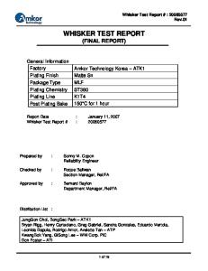
expansion joints or abutments. Figure 9 provides an example of a typical expansion‐deflection fitting installation between a bridge and an underground installation.
Figure 9: Conduit Expansion‐Deflection Fitting Source: WSDOT ITS Design Appendices
Conduit, Pull Box, and Splice Vault Installation in Clear Zone Conduit installation within the clear zone is done underground and should be installed at a depth of minimum depth of 24 inches, consistent with the conduit installation requirements specified in Caltrans ITS Special Provisions section 86‐ 6.14B. Where the conduit system is designated for fiber optic use, the innerduct should be encased with a red or orange pigmented cement to provide additional protection against conduit damage and to provide easy identification by field personnel. Warning tape with cautionary messaging should also be installed in accordance with Caltrans specification 86‐6.14H. Where the conduit system is designated for copper communications, standard PVC or HDPE conduit should be used. At conduit or innerduct entries to cabinet, cable vaults and pull boxes, the ends should be sealed with a sealing compound to prevent foreign material and rodents from entering the system. Conduit sections may be joined together using appropriate couplings but should not exceed a total of four quarter bends (360 degrees) for compliance with the National Electric Code (NEC). Lids for pull boxes and splice vaults shall be labeled according to Caltrans standard specifications to demarcate the functional use of the box and associated conduit system. Where possible, pull boxes and splice vaults shall be
Transpo Group
7-3
Gateway Cities Technology Plan for Goods Movement Technology Infrastructure Impacts
placed in the clear zone where the lid will not be subjected to regular vehicular loads. Where pull boxes and splice vaults are located in areas subjected to vehicular loading, the lid shall be rated to withstand AASHTO HS‐20‐44 loading. In all other locations, the lids shall be rated to AASHTO H5 loads.
Distribution and Backhaul Communication In order to support an extensive freeway ITS, connected‐vehicle and tolling system consisting of numerous ITS devices such as CCTV cameras, data stations, variable message signs, DSRC locations and tolling cabinets, etc. a distribution communication system is necessary to transfer information from each device through a network to a traffic management or other control center. A distribution fiber optic system would include cable terminations into the fiber distribution unit (FDU) of each cabinet. Fiber terminations should be prepared in accordance with the fiber specifications outlined in the Caltrans specification 86‐6.14K. Distribution communications systems differ from mainline communications as they typically intercept each ITS device along the corridor while mainline communications are primarily used for longer‐distance backhaul with very few intermediate splices. The purpose of a distribution system is to enable all devices to communicate over a common fiber optic cable that is often daisy‐chained to each device. Regardless of whether the system is designed for mainline or distribution needs, best practices recommend that communications system redundancies should be achieved through physical separation between the distribution and mainline communication conduits. This separation helps to maintain a path of communications in the event that one communication system is compromised. Best practices also recommend that ITS communication networks be separated from the tolling network through the use of dedicated fiber optic cables or strands and switching equipment where possible. Physical layer isolation minimizes the possibility that service disruptions to the ITS system would have on the revenue‐generating toll system and vice versa. Separation also enables required independent maintenance for the two systems.
Power Drop and Service In a freeway setting, power is provided from new or existing service drop locations through coordination with the utility providers. Conduit installation procedures should adhere to the Electrical Systems section of the Caltrans specifications and standard plans. Power conductors should not share a conduit system with the communication system. The type of power available from the power company can vary. A typical, household type of service of 120 VAC, 100 Amps is usually sufficient for the low power needs of the equipment in this report. However, in some cases, power may be provided at a higher voltage, usually 480 VAC, in which case, a step‐down transformer would be required to be installed adjacent to the device location requiring power. 7-4
Transpo Group
8.0 Summary The purpose of this report has been to present proposed technological equipment for Intelligent Transportation Systems (ITS), identify their functional specifications and their impact on infrastructure when applied to the Gateway Cities highways project on route I‐710 in Los Angeles County. Field device systems considered include Connected Vehicle, Automated Tolling (independent of Connected Vehicle deployment), Changeable Message Signs (CMS) and Closed Circuit Television (CCTV). Technology and infrastructure consideration for Truck Enforcement Network System (TENS) have been evaluated in another report. The infrastructure requirements for the Connected Vehicle system were developed with input from the USDOT’s Safety Pilot Model Deployment project which is occurring in Ann Arbor, Michigan. The proposed concept of operations for the zero‐emissions truck corridor has connected vehicle as one of the technological cornerstones of the envisioned facility. The use of connected vehicle applications is essential for improving safety, reducing environmental impacts, and optimizing the throughput of Zero Emission Trucks (ZET) in the Zero Emission Freight Corridor (ZEFC).
DSRC System The current national framework for the connected vehicle environment envisions the use of dedicated short range communication (DSRC) as one of the solutions for wireless communication. While it is anticipated that some applications and communication would be done over cellular, a DSRC radio would be capable of communicating with minimal latency over relatively short distances to ensure timely communication with all the ZETs on the corridor. For the purpose of this report, a dedicated DSRC infrastructure installation is conceptualized which includes a DSRC radio, pole, cabinet and equipment, communications (power box and cabling) and splice vaults and pull boxes. For at‐grade installation, DSRC radios should be installed at a height of 25 feet on a typical existing utility pole, to provide up to 1000 feet of wireless communication range. For installations on the elevated structure, a pole will need to be mounted on the median concrete barrier. The DSRC cabinet (preferably a NEMA 3R) used for DSRC cabinet equipment is typically pole mounted on the same pole as the DSRC radio at a height easily accessible for maintenance and installation.
Key Considerations:
Continuous coverage from DSRC radios can be obtained by spacing them every 4/10 of a mile (every 2000’). Fiber backhaul communication to be used along entire corridor.
Automated Tolling System While in theory connected vehicle technology could provide a means for a tolling system, the most impactful solution would be one that utilizes a dedicated, stand‐alone system electronic
8-1
Gateway Cities Technology Plan for Goods Movement Technology Infrastructure Impacts
tolling system as is currently being deployed today. This proposed technological solution will allow ZET in the ZEFC to be automatically tolled when crossing underneath a gantry. Tolling technology consists of placing gantries across the roadway to which license plate readers, strobes, sick scanners and AVI antenna will be attached to connect with a transponder in the vehicle. Toll gantries are typically either monotube sign bridges or cantilever structures, meeting Caltrans design criteria. Mounted to the first gantry, license plate capture cameras and laser measurement scanners detect the back of vehicles after they pass underneath the gantry in each lane. Toll controller cabinets are installed near each toll zone. The location typically has a maintenance vehicle pull‐off and a security fence for protection. In addition to the toll controller cabinet, a transformer cabinet and generator are installed adjacent to the toll controller cabinet.
Key Considerations:
Two toll NB entrance gantry points: Starting at the south end of the truck corridor, we have our first batch of northbound entrances from S Scenic Harbor Dr, Pico Av, N Harbor Av, and W Anaheim St. The current concept considers these all as the same tolled rate due to their close proximity to each other. The next northbound entrance from I‐710 General purpose just south of W Delamo will be considered as separate entrance point to the system with a different toll rate than the southernmost set of entrances.
Two toll gantry NB exit gantry points: The first NB exit point is at SR‐91 and will have a different toll rate that the other NB exit points. The next set of exit points will be considered at the same tolled rate due to their close proximity to each other. These are to Slauson Ave, to NB I‐710 general purpose and to E Washington Blvd. Two toll SB entrance gantry points: Starting at the north end of the truck corridor, we have our first batch of southbound entrances from SB I‐710 general purpose and from Slauson. The current concept considers these all as the same tolled entrance point due to their close proximity. There is another SB entrance point from WB SR‐91 which will be considered as separate entrance point to the system with a different toll. Two toll gantry SB exit gantry points: The first SB exit point is to EB SR‐91. This will be at a different rate than the other exit points which are bundled together at one rate. At the south end of the corridor are exits to I‐710 general purpose, to N. Harbor Ave, and to Pico Ave which are all considered the same tolled rate. Toll system gantry points will be co‐located with other ITS/DSRC equipment.
CMS System Changeable message signs (CMS) are electronic traffic signs used to inform travelers information about traffic congestion, accidents, construction, speed limits, or weather/road conditions.
8-2
Transpo Group
Gateway Cities Technology Plan for Goods Movement Technology Infrastructure Impacts
Three types of CMS have been proposed which include installations along the freight corridor, at toll locations, and approaching arterials: Freight corridor ‐ Largest display consisting of multiple changeable message panels. The purpose of this sign will be to display information to users of the freight corridor. Information includes travel times and traffic conditions. Arterial ‐Installed along the roadside or more rarely, on a signal pole. These signs inform drivers approaching the freight corridor of travel times and traffic conditions. An arterial sign is smaller in size. Toll rate ‐ Installed prior to toll zone access point and at the toll zone facility to inform freight corridor users of the toll fee. A toll rate sign consists of a static display and changeable message panels.
Key Considerations:
Three freight corridor signs anticipated. Initial estimates of arterial signs amount to thirteen. Three toll rate only signs anticipated.
CCTV System CCTV cameras will be added at strategic locations such as at large interchanges, to enable real time traffic monitoring as well as to provide aerial coverage of all installed ITS devices to ensure their proper functionality. CCTV poles provide a mounting location for the camera and are positioned at intervals along a corridor to prevent gaps in coverage. CCTV poles range in size and shall be placed such that the intersecting arterial, if applicable, is viewable and maintenance access is available. Installation of a CCTV camera on the elevated structure requires a 45’ CCTV pole extending from the concrete roadway barrier while CCTV installation on the at‐grade ZEFC requires mounting at a height of 25’ to 45’. CCTV camera cabinet and equipment typically consists of a pole mounted Type 336 cabinet on an elevated structure and a pad mounted cabinet for at‐grade roadside installations.
Key Considerations:
Twenty‐two total signs required for continuous coverage. Most cameras, fourteen, will be installed on the elevated structure. Remainder will be at‐grade. Co‐located with other devices if possible. Cameras will also be placed in locations so that sign messages can be visible.
Communication Backhaul System In order to support an extensive freeway ITS, connected‐vehicle and tolling system consisting of numerous ITS devices such as CCTV cameras, data stations, variable message signs, DSRC locations and tolling cabinets, etc. a distribution communication system is necessary to transfer information from each device through a network to a traffic management or other control center. Although many other mediums for communication exist, fiber optics have become the
Transpo Group
8-3
Gateway Cities Technology Plan for Goods Movement Technology Infrastructure Impacts
industry standard for high‐capacity and long‐distance data transfer on freeway systems at this time. With distance limitations imposed by fiber optic transmitters and receivers, it is common for communication hub facilities to be installed at major termination points and freeway junctions to aggregate data transmission and re‐distribute communications to other major hubs or transportation management centers.
Key Considerations:
It is likely that communications for revenue services (tolling) will need to be in a physically separated conduit system from other systems. Girder space under the elevated roadway structure will be utilized for conduit runs.
Cost Estimates The cost estimate for installation throughout the entire ZEFC is broken down by ITS type (DSRC, CMS, CCTV, and Communication Backhaul) and provided below:
Total Sites
Total Cost Per Subtotal Cost Installation $50,250 $1,155,750 $62,260 $249,040 $8,520 $187,440 $1,592,230
DSRC System: Elevated Structure DSRC System: At‐Grade Installation DSRC System: Combined with CCTV Total DSRC System
23 4 22
CMS System: Freight Corridor Installation CMS System: Arterial Installation CMS System: Toll Rate Sign Installation Total CMS System
3 13 3
$220,290 $194,500 $41,220
$660,870 $2,528,500 $123,660 $3,313,030
CCTV System: Elevated Structure CCTV System: At‐Grade Installation Total CCTV System
14 8
$55,890 $69,340
$782,460 $554,720 $1,337,180
Communication Backhaul System: Elevated Structure Communication Backhaul System: At‐Grade Installation Total Communication Backhaul System Total Corridor Costs :
8-4
$4,674,240 $1,661,760 $6,336,000 $12,578,440
Transpo Group
9.0 List of Reference Materials This Equipment Memorandum is intended to present technological equipment for ITS, identify their functional specifications and their impact on infrastructure when applied to the Gateway Cities highways project on route I‐710 in Los Angeles County. For individuals looking for greater detail on information referenced throughout this memorandum, please refer to the following resources used throughout its preparation: 2010 Standard Plans for CALTRANS
Barclays California Code of Regulations: Title 21, Chapter 16: Compatibility Specifications for Automatic Vehicle Identification Equipment California’s Definition for Title 21’s 32‐Bit Transponder ID Number Field CALTRANS Approved Title 21 Transaction Record Type Codes CALTRANS Electrical System, Section 86: Controller Cabinet Specifications CALTRANS Transportation Electrical Equipment Specifications Request for Proposed ACQ‐2012‐0406‐RFP, Washington State Roadway Toll Systems Savari Networks, StreetWAVE – Roadside Product Specifications Sheet Strategic Plan For the FasTrak Electronic Toll Collection System (May 2006) Transition Networks, SISGM1040‐224‐LRT Industrial Switch Cut Sheet TELVENT, SR 520 Toll Collection System As Built: Book #’s (1‐25) USDOT RITA’s, “5.9 GHz DSRC Roadside Equipment” Device Specification, March 2012 WSDOT’s “Active Traffic Management System I‐5, SR 520 and I‐90” prepared by DKS Associates and ELCON Corporation. WSDOT’s “Plan of Proposed State Highway Improvements, 520 Toll Collection System” WSDOT’s “NWR ITS Design Guide Supplement, Version: 7‐May‐10” WSDOT’s “Intelligent Transportation System (ITS) Design Guide, June 2004” WSDOT’s “ITS Standard Details, 2010” WSDOT’s RFP Standards, “Design‐Build Contracts, Chapter 2 Technical Requirements, WSDOT, I‐405/ NE 6th St, to I‐5 Widening and Express Toll Lanes Project, Request for Proposal. July 25, 2011” and Appendix Z4 WSDOT – Roadway Toll Systems Project, Appendix 2, 3, 11
Gateway Cities Technology Plan for Goods Movement Technology Infrastructure Impacts
Appendix A – Corridor Installation Map
APPENDIX A
Appendix B – Typical Installation Figures
APPENDIX B BARRIER
SHOULDER FREIGHT LANE
DIRECTION OF TRAFFIC
FREIGHT LANE SHOULDER
S V DSRC
MEDIAN BARRIER
CONNECTED VEHICLE / ITS FIBER OPTIC DISTRIBUTION CONDUIT / CABLE INSTALLED IN BOX GIRDER
SHOULDER FREIGHT LANE
FREIGHT LANE
DIRECTION OF TRAFFIC
SHOULDER BARRIER
LEGEND BARRIER PULL BOX
S
S V
SPLICE VAULT WITH SPLICE CLOSURE
V
DSRC
DSRC
DSRC POLE MOUNTED CABINET
DSRC RADIO AND POLE
CONDUIT AND FIBER TRUNK
DSRC MEDIAN BARRIER INSTALLATION
DSRC INSTALLATION PLAN FOR AN ELEVATED STRUCTURE (NTS)
DSRC ETHERNET SWITCH (POE)
ETHERNET SWITCH (BACKHAUL COMMUNICATIONS) DSRC RADIO
FIBER PATCH PANEL
25' - 30' DSRC POLE (TYP)
POWER DISTRIBUTION ASSEMBLY
PULL BOX IN BARRIER (COMMUNICATION) DSRC POLE MOUNTED CABINET CONCRETE BARRIER
TYPE 336 DSRC POLE MOUNTED CABINET LAYOUT
POWER PULL BOX IN BARRIER (ELECTRICAL) BRIDGE DECK
BOX GIRDER
CONNECTED VEHICLE / ITS FIBER OPTIC DISTRIBUTION CONDUIT / CABLE INSTALLED IN CONDUIT BANK
TO ELECTRICAL SERVICE CABINET SPLICE VAULT INSIDE BOX GIRDER AND ACCESSED FROM GIRDER OPENING UNDERNEATH STRUCTURE
CONNECTED VEHICLE / ITS FIBER OPTIC DISTRIBUTION CONDUIT / CABLE INSTALLED IN CONDUIT BANK
DSRC INSTALLATION ELEVATION FOR AN ELEVATED STRUCTURE (NTS)
SHOULDER
FREIGHT LANE FREIGHT LANE
DIRECTION OF TRAFFIC
SHOULDER MEDIAN SHOULDER MAINTENANCE VEHICLE PULLOUT
FREIGHT LANE
DIRECTION OF TRAFFIC
FREIGHT LANE
SHOULDER
LEGEND
CONNECTED VEHICLE / ITS FIBER OPTIC DISTRIBUTION CONDUIT / CABLE
S
GUARD RAIL
V
24"
POWER DISTRUBUTION CONDUIT / CABLE TO ELECTRICAL SERVICE CABINET
DSRC
PULL BOX
1"
CABINET BASE
24" 1"
S 24"
SPLICE VAULT CONCRETE PAD BACK
TRANS.
COMMUNICATION CONDUIT AND PRETERMINATED FIBER OPTIC CABLE
FRONT
24"
1"
TRANSFORMER
1"
DSRC POLE MOUNTED CABINET
CABINET BASE
V DSRC
DSRC RADIO AND POLE
TRANSFORMER FOUNDATION (IF NEEDED)
CONDUIT AND FIBER TRUNK
DSRC INSTALLATION PLAN FOR AT-GRADE ROADWAY (NTS)
DSRC ETHERNET SWITCH (POE)
ETHERNET SWITCH (BACKHAUL COMMUNICATIONS)
FIBER PATCH PANEL DSRC RADIO
25' DSRC POLE (TYP)
POWER DISTRIBUTION ASSEMBLY
TRANSFORMER CABINET (IF NEEDED) DSRC POLE MOUNTED CABINET
METAL BEAM GUARD RAIL
CONNECTED VEHICLE / ITS FIBER OPTIC DISTRIBUTION CONDUIT / CABLE
POWER PULL BOX PULL BOX
TYPE 336 DSRC POLE MOUNTED CABINET LAYOUT
TO ELECTRICAL SERVICE CABINET
SPLICE VAULT
DSRC INSTALLATION ELEVATION FOR AT-GRADE ROADWAY (NTS)
TOLL GANTRIES WITH TOLL READER GANTRY CABINET AND TOLL EQUIPMENT APPROX 1000' AFTER ENTRANCE POINT WITH 25' - 50' SPACING
TOLL RATE SIGN OVER GP LANES APPROX 300' BEFORE ENTRANCE POINT CONCRETE PAD
TR
TOLLED RAMP ENTRANCE
TR TC
T
TS
CV
T
CV
TOLL FIBER OPTIC DISTRIBUTION CONDUIT / CABLE
TOLL FIBER OPTIC DISTRIBUTION CONDUIT / CABLE
ENFORCEMENT AREA LOCATED WITH RESPECT TO TAG READER
LEGEND JUNCTION BOX CV
CABLE VAULT
TC
TOLL CONTROLLER CABINET
TR
TOLL READER GANTRY CABINET
TS
TOLL RATE SIGN CABINET TRANSFORMER CABINET
T
TOLL GANTRY TOLL RATE SIGN GANTRY CONDUIT AND FIBER TRUNK
TYPICAL TOLL ENTRANCE RAMP LAYOUT (NTS)
MAINTENANCE VEHICLE PULLOUT
TR
TR
TOLL ZONE 1 MONOTUBE STRUCTURE (DOWNSTREAM) WITH TOLL READER GANTRY CABINET. SEE TOLL GANTRY ELEVATION
SHOULDER FREIGHT LANE
DIRECTION OF TRAFFIC
FREIGHT LANE
MONOTUBE STRUCTURE (UPSTREAM) WITH TOLL GANTRY READER CABINET
MONOTUBE STRUCTURE (UPSTREAM) WITH TOLL READER GANTRY CABINET
SHOULDER MEDIAN SHOULDER MONOTUBE STRUCTURE (DOWNSTREAM) WITH TOLL READER GANTRY CABINET. SEE TOLL GANTRY ELEVATION
MAINTENANCE VEHICLE PULLOUT
FREIGHT LANE FREIGHT LANE
DIRECTION OF TRAFFIC
SHOULDER
TOLL ZONE 2
TOLL FIBER OPTIC DISTRIBUTION CONDUIT / CABLE
LEGEND
JUNCTION BOX
TC
POWER DISTRUBUTION CONDUIT / CABLE TO ELECTRICAL SERVICE CABINET COMMUNICATION CONDUIT AND PRETERMINATED FIBER OPTIC CABLE DOUBLE-WIDE ROADSIDE TOLL CABINET (TOLL ZONE 2)
TOLL FIBER OPTIC DISTRIBUTION CONDUIT / CABLE
TR
TR CV
CV
CABLE VAULT
T
TC
TOLL CONTROLLER CABINET
G
TR
TOLL READER GANTRY CABINET
TC
EMERGENCY BACKUP GENERATOR PAD
T
TRANSFORMER CABINET
G
GENERATOR
CONCRETE PAD TOLL GANTRY
MAINTENANCE ACCESS ROAD
DOUBLE-WIDE ROADSIDE TOLL CABINET (TOLL ZONE 1)
CONDUIT
CHAIN LINK FENCE EIGHT FEET IN HEIGHT WITH DOUBLE GATE FACING THE GENERATOR PAD
TYPICAL TOLL FACILITY LAYOUT (NTS)
LEGEND LICENSE PLATE IMAGE CAPTURE (LPIC) CAMERA
TOLL EQUIPMENT COMMUNICATION AND POWER
STROBE LASER SCANNER AUTOMATED VEHICLE IDENTIFICATION ANTENNA UNIT
TOLL READER GANTRY CABINET
SHOULDER
GP LANE
FREIGHT LANE
GP LANE
FIBER COMMUNICATION TO TOLL CONTROL CABINET
SHOULDER
TOLL GANTRY ELEVATION (DOWNSTREAM GANTRY) (NTS)
FIBER OPTIC PATCH PANEL
FIBER PATCH PANEL
FIBER OPTIC PATCH PANEL
SWITCH
FIBER PATCH PANEL
SWITCH
ZONE 1 CONTROLLER UPSTREAM
ZONE 1 CONTROLLER UPSTREAM
ZONE 2 CONTROLLER UPSTREAM
ZONE 2 CONTROLLER UPSTREAM
ZONE 1 CONTROLLER DOWNSTREAM
ZONE 1 CONTROLLER DOWNSTREAM
ZONE 2 CONTROLLER DOWNSTREAM
ZONE 2 CONTROLLER DOWNSTREAM
IMAGE CAPTURE STATION 1
IMAGE CAPTURE STATION 1
IMAGE CAPTURE STATION 2
IMAGE CAPTURE STATION 2
DIGITAL VIDEO AUDITING SYSTEM DVR 1
DIGITAL VIDEO AUDITING SYSTEM DVR 2
DIGITAL VIDEO AUDITING SYSTEM DVR 2
UPS A
UPS B
DIGITAL VIDEO AUDITING SYSTEM DVR 1 UPS A
POWER DISTRIBUTION ASSEMBLY
BATTERIES FOR UPS A AND UPS B
SIDE VIEW (LEFT SIDE)
UPS B
POWER DISTRIBUTION ASSEMBLY
BATTERIES FOR UPS A AND UPS B
FRONT VIEW
TOLL CONTROL CABINET ELEVATION (NTS)
SIDE VIEW (RIGHT SIDE)
SHOULDER FREIGHT LANE
DIRECTION OF TRAFFIC
FREIGHT LANE SHOULDER MEDIAN SHOULDER MAINTENANCE VEHICLE PULLOUT
FREIGHT LANE
FREIGHT LANE
DIRECTION OF TRAFFIC
SHOULDER GUARD RAIL
S
24"
V
ITS FIBER OPTIC DISTRIBUTION CONDUIT / CABLE
1"
CABINET BASE
24" 1"
24"
CONCRETE PAD
CMS
CMS CABINET
CMS CABINET
1"
BACK
POWER DISTRUBUTION CONDUIT / CABLE TO ELECTRICAL SERVICE CABINET
CABLE VAULT
BACK
CABINET BASE
PULL BOX
S V
6"
COMMUNICATION CONDUIT AND PRETERMINATED FIBER OPTIC CABLE
CMS
LEGEND
CABINET BASE
TRANS. CABINET FRONT 1"
FRONT
24"
TRANSFORMER CABINET
CHANGEABLE MESSAGE SIGN AND STRUCTURE
CCTV AND TRANSFORMER CABINET FOUNDATION
CONDUIT AND FIBER TRUNK
CMS INSTALLATION PLAN FOR AT-GRADE ROADWAY (NTS)
30'-1" LIMITS OF TRUSS AND WALKWAY 15'- "
15'- "
28'-7" (CHORD LENGTH) LIMITS OF TRUSS AND WALKWAY
25'-6"
• POST
6'-9" CMS
6'-9" CMS
7'-2" FRAME DEPTH
CMS MODEL 500
7'-2" FRAME DEPTH
CMS MODEL 500
BOTTOM OF TRUSS
BOTTOM OF TRUSS
2'-6"
5 @ 5'-6" = 27'-6" WALKWAY BRACKET SPACING (NOT ALL WALKWAY MEMBERS SHOWN)
7"
"h" 24'-0" Max SEE PROJECT PLANS
"h" 24'-0" MAXIMUM SEE PROJECT PLANS
(WALKWAY BRACKETS, TOTAL 7 MINIMUM, SPACING MAY VARY)
CMS UNBALANCED BUTTERFLY ELEVATION
CMS BALANCED BUTTERFLY ELEVATION
(NTS)
(NTS)
BARRIER
SHOULDER FREIGHT LANE
DIRECTION OF TRAFFIC
FREIGHT LANE SHOULDER
S V CCTV
MEDIAN BARRIER
ITS FIBER OPTIC DISTRIBUTION CONDUIT / CABLE INSTALLED IN BOX GIRDER
SHOULDER FREIGHT LANE
FREIGHT LANE
DIRECTION OF TRAFFIC
SHOULDER BARRIER
LEGEND BARRIER PULL BOX
S
S V
POWER DISTRUBUTION CONDUIT / CABLE TO ELECTRICAL SERVICE CABINET
V
SPLICE VAULT WITH SPLICE CLOSURE
CCTV
CCTV
CCTV POLE MOUNTED CABINET
CCTV CAMERA AND POLE
CCTV MEDIAN BARRIER INSTALLATION
CONDUIT AND FIBER TRUNK
CCTV INSTALLATION PLAN FOR AN ELEVATED STRUCTURE (NTS)
CCTV CAMERA
VIDEO & DATA TRANSMITTER
ETHERNET SWITCH (BACKHAUL COMMUNICATIONS)
45' CCTV POLE (TYP)
FIBER PATCH PANEL
POWER DISTRIBUTION ASSEMBLY
PULL BOX IN BARRIER (COMMUNICATION) CCTV POLE MOUNTED CABINET CONCRETE BARRIER POWER PULL BOX IN BARRIER (ELECTRICAL)
TYPE 336 CCTV POLE MOUNTED CABINET LAYOUT
BRIDGE DECK
BOX GIRDER
ITS FIBER OPTIC DISTRIBUTION CONDUIT / CABLE INSTALLED IN CONDUIT BANK
TO ELECTRICAL SERVICE CABINET SPLICE VAULT INSIDE BOX GIRDER AND ACCESSED FROM GIRDER OPENING UNDERNEATH STRUCTURE
ITS FIBER OPTIC DISTRIBUTION CONDUIT / CABLE INSTALLED IN CONDUIT BANK
CCTV INSTALLATION ELEVATION FOR AN ELEVATED STRUCTURE (NTS)
SHOULDER FREIGHT LANE
DIRECTION OF TRAFFIC
FREIGHT LANE SHOULDER MEDIAN SHOULDER MAINTENANCE VEHICLE PULLOUT
FREIGHT LANE
FREIGHT LANE
DIRECTION OF TRAFFIC
SHOULDER GUARD RAIL
S
24"
V
ITS FIBER OPTIC DISTRIBUTION CONDUIT / CABLE
CABINET BASE
1"
24" 1"
24"
CONCRETE PAD
CCTV
CCTV CABINET
CCTV CABINET
1"
BACK
POWER DISTRUBUTION CONDUIT / CABLE TO ELECTRICAL SERVICE CABINET
CABLE VAULT
BACK
CABINET BASE
PULL BOX
S V
CABINET BASE
COMMUNICATION CONDUIT AND PRETERMINATED FIBER OPTIC CABLE
CCTV
LEGEND
6"
TRANS. CABINET FRONT 1"
FRONT
24"
TRANSFORMER CABINET
CCTV CAMERA AND POLE
CCTV AND TRANSFORMER CABINET FOUNDATION
CONDUIT AND FIBER TRUNK
CCTV INSTALLATION PLAN FOR AT-GRADE ROADWAY (NTS)
VIDEO & DATA TRANSMITTER
CCTV CAMERA
EATHERNET SWITCH (BACKHAUL COMMUNICATIONS) AND FIBER PATCH PANEL
45' CCTV POLE (TYP)
PULL-OUT DRAWER
CCTV CABINET TRANSFORMER METAL BEAM GUARD RAIL POWER DISTRIBUTION ASSEMBLY
HEATER
SPLICE VAULT
PULL BOX TO ELECTRICAL SERVICE CABINET
TYPE 334 CCTV CABINET LAYOUT
POWER PULL BOX ITS FIBER OPTIC DISTRIBUTION CONDUIT / CABLE
CCTV INSTALLATION ELEVATION FOR AT-GRADE ROADWAY (NTS)
WIDENED BARRIER FOR BARRIER MOUNTED POLE PULL BOX IN BARRIER PULL BOX IN BARRIER IF ADJACENT TO BARRIER MOUNTED POLE
FOUNDATION FOR BARRIER MOUNTED POLE
PULL BOX IN BARRIER IF ADJACENT TO BARRIER MOUNTED POLE
CONDUIT BANKS
TYPICAL ELEVATED STRUCTURE LAYOUT (NTS)
POLE MOUNTED CABINET
POLE MOUNTED CABINET
BASE PLATE PULL BOX IN TRAFFIC BARRIER
PULL BOX IN TRAFFIC BARRIER ANCHOR BOLTS (4) CONCRETE TRAFFIC BARRIER
CONCRETE MEDIAN TRAFFIC BARRIER
ANCHOR PLATE
PULL BOX IN TRAFFIC BARRIER
PULL BOX IN TRAFFIC BARRIER
BARRIER MOUNTED POLE DETAILS (NTS)
BRIDGE LAYOUT LINE DIMENSION SHOWN ON BRIDGE DETAIL PLANS
CONDUIT PASSING THROUGH GIRDER OR DIAPHRAGM OF BOX GIRDER SECTION SHALL BE EITHER CAST INTO CONCRETE OR PASSED THROUGH OPENING. OPENING SHALL NOT BE DRAINAGE OPENING AND SHALL BE ONLY AS LARGE AS REQUIRED TO INSTALL CONDUIT. CONDUIT SHALL BE RUN EITHER PARALLEL TO OR AT RIGHT ANGLES TO GIRDERS.
2" Min
CONCRETE CRADLES @ 10'-0" CENTERS UNDER THE FIRST CRADLE SUPPORT INSIDE BRIDGE NEAR ABUTMENT OR HINGE, EPOXY 12 GAGE GALVANIZE STEEL SHEET 2'-8" x 1'-4" TO THE FLOOR OF CELL. DO NOT SECURE CRADLE TO STEEL SHEET. CRADLE SHALL BE FREE TO SLIDE TO ACCOMMODATE LATERAL MOVEMENT.
2" Min
TYPE 1 CONDUIT
FOR SUPPORT, SEE STANDARD PLAN B14-3. FLUSH SOFFIT LUMINAIRE OR CEILING PB
STEM OR DIAPHRAGM
BOX GIRDER CONDUIT SUPPORT DETAILS
CONDUIT INSTALLATION WITHIN BOX GIRDER SECTIONS
(NTS)
(NTS)
CONDUIT CRADLES RADIUS AS REQUIRED TO MATCH CONDUIT OR PIPE SIZE HALF CONDUIT Dia
ALLOW FREEDOM TO SLIDE
3"
VARIES 4" Min
EPOXY ADHESIVE 8"
2" x 2" - W2.0 x W2.0 WELDED WIRE FABRIC BRIDGE SOFFIT NOTES: 1. CRADLES TO BE PRECAST CONCRETE. 2. SECURE ALL CRADLES TO BOTTOM SLAB OF BRIDGE WITH EPOXY ADHESIVE, EXCEPT AS PROVIDED ABOVE.
CONCRETE CRADLE (NTS)
EXPANSION FITTING/COUPLING 2" Max CONDUIT
EXPANSION FITTING/COUPLING 2"
PB
TYPE 1 CONDUIT 1'-0" LENGTH TYPE 4 CONDUIT CONDUIT UNION TYPE 1 CONDUIT
CONC. OR STEEL GIRDER No. 6 BONDING STRAP
2" Max CONDUIT COUPLING 3" Max CONDUIT
BENT
CONDUIT RISER CONNECTION (NTS)
CONDUIT IN BRIDGE RAILING (NTS)
PULL BOX AXIS PARALLEL BONDING TO TOP OF JUMPER BARRIER ELECTROLIER CONDUIT
No. 9A PULL BOX DRAIN TYPICAL FOR TYPE 25 OR TYPE 26 CONCRETE BARRIERS
ELECTROLIER ANCHOR BONDING STRAP
ANCHOR PLATE
THROUGH CONDUIT
THROUGH CONDUIT
END VIEW
SIDE VIEW BOLT CIRCLE
.
. . . . .. . . . .
BONDING JUMPER
3'-4" Min
TOP VIEW
No. 9A PULL BOX
ELECTROLIER CONDUIT THROUGH CONDUIT
DRAIN
TYPICAL FOR TYPE 25 OR TYPE 26 CONCRETE BARRIERS
ELECTROLIER ANCHOR BONDING STRAP
ANCHOR PLATE BONDING JUMPER
THROUGH CONDUIT
END VIEW SIDE VIEW BARRIER PULL BOX & CONDUIT DETAILS (NTS)
RESTORE TO MATCH EXISTING SURFACE. 12" MIN
6"
24" MIN
12"
3" WIDE POLYETHYLENE DETECTABLE WARNING TAPE WITH METALLIC BACKING PER WSDOT STANDARD SPECIFICATIONS. BACKFILL WITHIN PAVED CITY STREETS, DRIVEWAYS AND UNDER CURB, GUTTER AND SIDEWALKS WILL CONSIST OF CONTROL DENSITY FILL (CDF) WITH THE MAXIMUM STRENGTH OF 150PSI. MIX DESIGN TO BE APPROVED BY THE CITY OR BACKFILL SHALL BE COMPACTED TO 95% MAXIMUM DENSITY IN 6" MAXIMUM LIFTS. LANDSCAPED AREAS SHALL BE BACKFILLED AND COMPACTED TO 85% MAXIMUM DENSITY IN 12" LIFTS. NOTE: ALL DENSITIES SHALL BE AS DETERMINED BY MODIFIED PROCTOR (ASTM D1557)
SAND
NEW CONDUIT WITH LOCATE WIRE INSTALLED DIRECTLY ABOVE CONDUIT PER WSDOT STANDARD SPECIFICATIONS (SEE PLANS FOR SIZE AND QUANTITY)
TRENCHING DETAIL (NTS)
Gateway Cities Technology Plan for Goods Movement Technology Infrastructure Impacts
Appendix C – Cost Estimates
APPENDIX C DSRC SYSTEM The following is a preliminary, conceptual estimate of cost based on recent public bids. The intent of the estimates is to gauge an order of magnitude cost for proposed technology items and should not be utilized for budgeting purposes. ITEM DSRC SYSTEM: Elevated Structure DSRC Antenna Unit (with Mount) DSRC Cabling (CAT6) 25' Utility Pole Utility Pole Anchor Bolts Pole‐Mounted DSRC Cabinet (Model 336) Ethernet Switch Fiber Optic Patch Panel (12 Port) Fiber Optic Splice Closure Preterminated Stub Cable (12 SMFO) 3" Conduit (RGS) Pull Box (Structure) Electrical Service Cabinet and Foundation Cabinet Power Cabling 20% Contingency Total Cost per Installation DSRC SYSTEM: At‐Grade Installation DSRC Antenna Unit (with Mount) DSRC Cabling (CAT6) 25' Utility Pole Utility Pole Foundation CCTV Cabinet (Model 334) and Foundation Ethernet Switch Fiber Optic Patch Panel (12 Port) Fiber Optic Splice Closure Preterminated Stub Cable (12 SMFO) 3" Conduit (PVC) Pull Box (Ground) Electrical Service Cabinet and Foundation Cabinet Power Cabling Trenching 20% Contingency Total Cost per Installation DSRC SYSTEM: Combined with CCTV DSRC Antenna Unit (with Mount) DSRC Cabling (CAT6) 20% Contingency Total Cost per Installation
Unit
Total Quantity
E.A. L.F. E.A. E.A. E.A. E.A. E.A. E.A. L.F. L.F. E.A. E.A. L.F.
1 100 1 1 1 1 1 1 40 200 5 1 500
$6,800 $1.50 $5,000.00 $500.00 $4,000.00 $3,000.00 $2,300.00 $1,400.00 $3.00 $18.00 $1,800.00 $5,500.00 $1.00
E.A. L.F. E.A. E.A. E.A. E.A. E.A. E.A. L.F. L.F. E.A. E.A. L.F. L.F.
1 200 1 1 1 1 1 1 60 300 5 1 500 150
$6,800 $6,800.00 $1.50 $300.00 $5,000.00 $5,000.00 $1,000.00 $1,000.00 $7,000.00 $7,000.00 $3,000.00 $3,000.00 $2,300.00 $2,300.00 $1,400.00 $1,400.00 $3.00 $180.00 $8.00 $2,400.00 $2,800.00 $14,000.00 $5,500.00 $5,500.00 $1.00 $500.00 $20.00 $3,000.00 $9,880.00 $62,260.00
E.A. L.F.
1 200
$6,800 $1.50
Total Cost per Subtotal Cost Installation 23 $50,250.00 $1,155,750.00 4 $62,260.00 $249,040.00 22 $8,520.00 $187,440.00 $1,592,230.00
Total Sites DSRC SYSTEM: Elevated Structure DSRC SYSTEM: At‐Grade Installation DSRC SYSTEM: Combined with CCTV TOTAL DSRC SYSTEM
Unit Price
Total Cost $6,800.00 $150.00 $5,000.00 $500.00 $4,000.00 $3,000.00 $2,300.00 $1,400.00 $120.00 $3,600.00 $9,000.00 $5,500.00 $500.00 $8,380.00 $50,250.00
$6,800.00 $300.00 $1,420.00 $8,520.00
CMS SYSTEM The following is a preliminary, conceptual estimate of cost based on recent public bids. The intent of the estimates is to gauge an order of magnitude cost for proposed technology items and should not be utilized for budgeting purposes. ITEM CMS SYSTEM: Freight Corridor Installation Changeable Message Sign (Large) Changeable Message Sign Coax Cabling Cantilever Sign Structure Sign Structure Anchor Bolts Pole‐Mounted CCTV Cabinet (Model 336) Sign Controller Auxilary Control Panel Ethernet Switch Fiber Optic Patch Panel (12 Port) Fiber Optic Splice Closure Preterminated Stub Cable (12 SMFO) 3" Conduit (RGS) Pull Box (Structure) Electrical Service Cabinet and Foundation Cabinet Power Cabling 20% Contingency Total Cost per Installation CMS SYSTEM: Arterial Installation Changeable Message Sign (Small) Changeable Message Sign Coax Cabling Cantilever Sign Structure Sign Structure Foundation CCTV Cabinet (Model 334) and Foundation Sign Controller Auxilary Control Panel Ethernet Switch Fiber Optic Patch Panel (12 Port) Fiber Optic Splice Closure Preterminated Stub Cable (12 SMFO) 3" Conduit (PVC) Pull Box (Ground) Electrical Service Cabinet and Foundation Cabinet Power Cabling Trenching 20% Contingency Total Cost per Installation
Unit
Total Quantity
E.A. L.F. E.A. E.A. E.A. E.A. E.A. E.A. E.A. E.A. L.F. L.F. E.A. E.A. L.F.
1 100 1 1 1 1 1 1 1 1 40 200 5 1 500
E.A. L.F. E.A. E.A. E.A. E.A. E.A. E.A. E.A. E.A. L.F. L.F. E.A. E.A. L.F. L.F.
1 200 1 1 1 1 1 1 1 1 60 300 5 1 500 150
$60,000.00 $1.50 $33,000.00 $20,000.00 $7,000.00 $7,000.00 $3,000.00 $3,000.00 $2,300.00 $1,400.00 $3.00 $8.00 $2,800.00 $5,500.00 $1.00 $20.00
$60,000.00 $300.00 $33,000.00 $20,000.00 $7,000.00 $7,000.00 $3,000.00 $3,000.00 $2,300.00 $1,400.00 $180.00 $2,400.00 $14,000.00 $5,500.00 $500.00 $3,000.00 $31,920.00 $194,500.00
1 100 1 1 1 1 200 2
$10,000.00 $1.50 $4,000.00 $7,000.00 $3,000.00 $3,000.00 $18.00 $1,800.00
$10,000.00 $150.00 $4,000.00 $7,000.00 $3,000.00 $3,000.00 $3,600.00 $3,600.00 $6,870.00 $41,220.00
CMS SYSTEM: Toll Rate Sign Installation (at Toll Location) E.A. Toll Rate Sign L.F. Toll Rate Sign Coax Cabling E.A. Pole‐Mounted CMS Cabinet (Model 336) E.A. Sign Controller E.A. Auxilary Control Panel E.A. Ethernet Switch L.F. 3" Conduit (RGS) E.A. Pull Box (Structure) 20% Contingency Total Cost per Installation
Total Cost
$110,000.00 $110,000.00 $1.50 $150.00 $33,000.00 $33,000.00 $1,000.00 $1,000.00 $4,000.00 $4,000.00 $7,000.00 $7,000.00 $3,000.00 $3,000.00 $3,000.00 $3,000.00 $2,300.00 $2,300.00 $1,400.00 $1,400.00 $3.00 $120.00 $18.00 $3,600.00 $1,800.00 $9,000.00 $5,500.00 $5,500.00 $1.00 $500.00 $36,720.00 $220,290.00
Total Cost per Subtotal Cost Installation 3 $220,290.00 $660,870.00 13 $194,500.00 $2,528,500.00 3 $41,220.00 $123,660.00 $3,313,030.00
Total Sites CMS SYSTEM: Freight Corridor Installation CMS SYSTEM: Arterial Installation CMS SYSTEM: Toll Rate Sign Installation TOTAL CMS SYSTEM
Unit Price
CCTV SYSTEM The following is a preliminary, conceptual estimate of cost based on recent public bids. The intent of the estimates is to gauge an order of magnitude cost for proposed technology items and should not be utilized for budgeting purposes. ITEM CCTV SYSTEM: Elevated Structure Standard CCTV Camera CCTV Camera Cabling (CAT6) 45' CCTV Pole CCTV Pole Anchor Bolts Pole‐Mounted CCTV Cabinet (Model 336) Ethernet Switch Fiber Optic Patch Panel (12 Port) Fiber Optic Splice Closure Preterminated Stub Cable (12 SMFO) 3" Conduit (RGS) Pull Box (Structure) Electrical Service Cabinet and Foundation Cabinet Power Cabling 20% Contingency Total Cost per Installation CCTV SYSTEM: At‐Grade Installation Standard CCTV Camera CCTV Camera Cabling (CAT6) 45' CCTV Pole CCTV Pole Foundation CCTV Cabinet (Model 334) and Foundation Ethernet Switch Fiber Optic Patch Panel (12 Port) Fiber Optic Splice Closure Preterminated Stub Cable (12 SMFO) 3" Conduit (PVC) Pull Box (Ground) Electrical Service Cabinet and Foundation Cabinet Power Cabling Trenching 20% Contingency Total Cost per Installation
Unit
Total Quantity
E.A. L.F. E.A. E.A. E.A. E.A. E.A. E.A. L.F. L.F. E.A. E.A. L.F.
1 100 1 1 1 1 1 1 40 200 5 1 500
$6,500.00 $6,500.00 $1.50 $150.00 $10,000.00 $10,000.00 $500.00 $500.00 $4,000.00 $4,000.00 $3,000.00 $3,000.00 $2,300.00 $2,300.00 $1,400.00 $1,400.00 $3.00 $120.00 $18.00 $3,600.00 $1,800.00 $9,000.00 $5,500.00 $5,500.00 $1.00 $500.00 $9,320.00 $55,890.00
E.A. L.F. E.A. E.A. E.A. E.A. E.A. E.A. L.F. L.F. E.A. E.A. L.F. L.F.
1 250 1 1 1 1 1 1 60 300 5 1 400 150
$6,500.00 $6,500.00 $1.50 $375.00 $10,000.00 $10,000.00 $2,800.00 $2,800.00 $7,000.00 $7,000.00 $3,000.00 $3,000.00 $2,300.00 $2,300.00 $1,400.00 $1,400.00 $3.00 $180.00 $8.00 $2,400.00 $2,800.00 $14,000.00 $5,500.00 $5,500.00 $1.00 $400.00 $20.00 $3,000.00 $10,480.00 $69,340.00
Total Sites CCTV SYSTEM: Elevated Structure CCTV SYSTEM: At‐Grade Installation TOTAL CCTV SYSTEM
14 8
Unit Price
Total Cost per Subtotal Cost Installation $55,890.00 $69,340.00
$782,460.00 $554,720.00 $1,337,180.00
Total Cost
COMMUNICATION BACKHAUL SYSTEM The following is a preliminary, conceptual estimate of cost based on recent public bids. The intent of the estimates is to gauge an order of magnitude cost for proposed technology items and should not be utilized for budgeting purposes. ITEM
Unit
COMMUNICATION BACKHAUL SYSTEM: Elevated Structure L.F. Fiber Backhaul Communication (96 SMFO) L.F. 3" Conduit (RGS) E.A. Pull Box (Structure) 20% Contingency Total Cost per Installation COMMUNICATION BACKHAUL SYSTEM: At‐Grade Installation L.F. Fiber Backhaul Communication (96 SMFO) L.F. 3" Conduit (PVC) E.A. Pull Box (Ground) L.F. Trenching 20% Contingency Total Cost per Installation COMMUNICATION BACKHAUL SYSTEM: Elevated Structure COMMUNICATION BACKHAUL SYSTEM: At‐Grade Installation TOTAL COMMUNICATION BACKHAUL SYSTEM
Total Quantity Unit Price
Total Cost
180000 168000 84
$4.00 $720,000.00 $18.00 $3,024,000.00 $1,800.00 $151,200.00 $779,040.00 $4,674,240.00
70000 60600 30 30300
$3.00 $8.00 $2,800.00 $20.00
$4,674,240.00 $1,661,760.00 $6,336,000.00
$210,000.00 $484,800.00 $84,000.00 $606,000.00 $276,960.00 $1,661,760.00
Appendix D – Sample Plan Sheets
APPENDIX D DRAFT - FOR INFORMATIONAL USE ONLY
DIST
COUNTY
ROUTE
X
X
X
POST MILES TOTAL PROJECT
X
No
FESSIO RO N P A
DATE D
TOTAL SHEETS
L
E
R
E
REGISTERED CIVIL ENGINEER
SHEET
? ?
No.
Exp.
The State of California or its officers or agents
completeness of scanned copies of this plan sheet.
S
shall not be responsible for the accuracy or
T A T E
NEER
DATE
GI
APPROVAL
R E G IS T
E
N
PLANS
?
CIVIL IA RN OF IFO CAL
POTENTIAL CMS LOCATION FOR EB SLAUSON AVE TO SB FREIGHT CORRIDOR
I-5 INT ERC HAN GE
POTENTIAL CMS LOCATION FOR WB SLAUSON AVE TO SB FREIGHT CORRIDOR
POTENTIAL NORTH TOLL FACILITY LOCATION (BOTH DIRECTIONS)
=> $TIM E
I-105 INTERCHANGE
TIM E
P LOTTED
SR 91 INTERCHANGE
DESIGN OVERSIGHT
X BY
DETAILS
X
X BY
QUANTITIES SIGN OFF DATE
DESIGN GENERAL PLAN SHEET (ENGLISH) (REV. 06-01-09)
X
CHECKED
X
LOAD & RESISTANCE FACTOR DESIGN
CHECKED
X
BY
LAYOUT
CHECKED
X
X BY
SPECIFICATIONS
X
LIVE LOADING:
HL93 W/"LOW-BOY";
PERMIT DESIGN VEHICLE
X PLANS AND SPECS COMPARED
X
BRIDGE NO.
PREPARED FOR THE
STATE OF CALIFORNIA
CHECKED
X
X PROJECT ENGINEER
POST MILES
MOCK-UP ITS DESIGN PLAN
DEPARTMENT OF TRANSPORTATION CU X EA X FILE => $REQUEST
REVISION DATES (PRELIMINARY STAGE ONLY)
SHEET
OF
DISREGARD PRINTS BEARING EARLIER REVISION DATES
X
X
X
U SER N A M E
BY DESIGN
X
=> $U SER
D A TE
P LOTTED
=>$D A TE
I-405 INTERCHANGE
DIST
COUNTY
ROUTE
?
?
?
DRAFT - FOR INFORMATIONAL USE ONLY
POST MILES TOTAL PROJECT
?
No
FESSIO RO N P A
DATE D
TOTAL SHEETS
L
E
R
E
REGISTERED CIVIL ENGINEER
SHEET
? ?
No.
Exp.
The State of California or its officers or agents
completeness of scanned copies of this plan sheet.
S
shall not be responsible for the accuracy or
T A T E
NEER
DATE
GI
APPROVAL
R E G IS T
E
N
PLANS
?
CIVIL IA RN OF IFO CAL
I-5 INTERCHANGE POTENTIAL TOLL EXIT RAMP LOCATION FOR SB FREIGHT CORRIDOR TO SB I-710
POTENTIAL TOLL ENTRANCE RAMP LOCATION FOR NB I-710 TO NB FREIGHT CORRIDOR
=> $TIM E
I-105 INTERCHANGE
TIM E
P LOTTED
SR 91 INTERCHANGE
DESIGN OVERSIGHT
X BY
DETAILS
X
X BY
QUANTITIES SIGN OFF DATE
DESIGN GENERAL PLAN SHEET (ENGLISH) (REV. 06-01-09)
X
CHECKED
X
LOAD & RESISTANCE FACTOR DESIGN
CHECKED
X
BY
LAYOUT
CHECKED
X
X BY
SPECIFICATIONS
X
LIVE LOADING:
HL93 W/"LOW-BOY";
PERMIT DESIGN VEHICLE
X PLANS AND SPECS COMPARED
X
BRIDGE NO.
PREPARED FOR THE
STATE OF CALIFORNIA
CHECKED
X
X
X
PROJECT ENGINEER
DEPARTMENT OF TRANSPORTATION
POST MILES
X CU X EA X FILE => $REQUEST
MOCK-UP ITS DESIGN PLAN REVISION DATES (PRELIMINARY STAGE ONLY)
SHEET
OF
DISREGARD PRINTS BEARING EARLIER REVISION DATES
X
X
X
U SER N A M E
BY DESIGN
X
=> $U SER
D A TE
P LOTTED
=>$D A TE
I-405 INTERCHANGE
DIST
COUNTY
ROUTE
?
?
?
DRAFT - FOR INFORMATIONAL USE ONLY
POST MILES TOTAL PROJECT
?
No
FESSIO RO N P A
DATE D
TOTAL SHEETS
L
E
R
E
REGISTERED CIVIL ENGINEER
SHEET
? ?
No.
Exp.
The State of California or its officers or agents
completeness of scanned copies of this plan sheet.
S
shall not be responsible for the accuracy or
T A T E
NEER
DATE
GI
APPROVAL
R E G IS T
E
N
PLANS
?
CIVIL IA RN OF IFO CAL
POTENTIAL CCTV/DSRC INSTALLATION ON ELEVATED STRUCTURE I-5 INTERCHANGE
POTENTIAL CMS LOCATION FOR WB ANAHEIM ST TO NB FREIGHT CORRIDOR
=> $TIM E
I-105 INTERCHANGE
TIM E
P LOTTED
SR 91 INTERCHANGE
POTENTIAL CMS LOCATION FOR EB ANAHEIM ST TO NB FREIGHT CORRIDOR
DESIGN OVERSIGHT
X BY
DETAILS
X
X BY
QUANTITIES SIGN OFF DATE
DESIGN GENERAL PLAN SHEET (ENGLISH) (REV. 06-01-09)
X
CHECKED
X
LOAD & RESISTANCE FACTOR DESIGN
CHECKED
X
BY
LAYOUT
CHECKED
X
X BY
SPECIFICATIONS
X
LIVE LOADING:
HL93 W/"LOW-BOY";
X
CHECKED
STATE OF CALIFORNIA
X PLANS AND SPECS COMPARED
BRIDGE NO.
PREPARED FOR THE
PERMIT DESIGN VEHICLE
DEPARTMENT OF TRANSPORTATION
X
FOR REDUCED PLANS 0
1
2
POST MILES
X
ORIGINAL SCALE IN INCHES 3
X
X
PROJECT ENGINEER
CU X EA X FILE => $REQUEST
MOCK-UP ITS DESIGN PLAN REVISION DATES (PRELIMINARY STAGE ONLY)
SHEET
OF
DISREGARD PRINTS BEARING EARLIER REVISION DATES
X
X
X
U SER N A M E
BY DESIGN
X
=> $U SER
D A TE
P LOTTED
=>$D A TE
I-405 INTERCHANGE
Gateway Cities Technology Plan for Goods Movement Technology Infrastructure Impacts
Appendix E – Caltrans Standard Plans
APPENDIX E