Efrect of Stabilizer
On The Mechanical Properties of Rigid PVC
Effect of Stabilizer on the Mechanical Properties of Rigid Polyvinyl Chloride
by Karl K.T. Woo, B.S.
A Project
Repo~t
Submitted to the School of Graduate Studies in :Partial Fulfilment of the Requirements for the Degree Master of Engineering
McMaster University September
1974'
Jluter. o·f Engineer \ng ( 197 4)
MCMaster UniTersity
(Chemi cal Engineerilng) -
Hamilton, Ontario
Bffuct ef Stabilizer on the Mechanical Properties
!I!LE
ef Higid Polyvinyl Chloride AUTHOR:
Karl. K.T. Woo, B.S. Chem. Eng. (Lo1rell Technological tnstitute, Yass. U.S.A.)
SUPERVISOR:
Dr. A.E. Hamielec and Dr. J. Vl achopoulo&
NUllBER OF PAGES:
v, 95
SCOPE & CONTENTS: In this stll.dy commercial suspension polymerized polyvinyl chloride resin ri tb. different stabilizer contents was first compounded and
inj~ctioned
molded into small dumbbell shape specimens. Most of the
specimens after annealing were then tested on the Instron Tensile Tester while the rest on l.liniature Tensile Tester for difference in mechanical properties. Four parameters from the stress-strain curves were· of interest in this study: tensile yield stress, tensile modulus, elongation at fracture and
~ltimate
fracture strength. The differences in mechanical
properties were explained by the change in molecul ar structure of polyTiny! chloride brought about by the reaction between the stabilizer and PVC molecules. In tne second part of the experiment, the effects of heat treatment and molecmlar weight on the mechanical properties of rigid PVC wer e also investigated. ii
ACKNOWLEDGEMENTS
The
auth~r
gratefully
ackn~wledges
the guidance and
encour~
a gement from Proiessor A.E. Hamielec, Professor J. Vlachopoulos and Dr. D. Shinozaki throughout the length of this work. Financial assistance in the form of a McMaster University Scholarship is also gratefully
appreciated~
iii
T A B' L E 0 F C 0 NT EN T S -----------------PAGE . .......... . I NTRODUCTION. • • • • • 2. REVIEW OF LITERATURE • . . . . . . . . . . . . . . . . . . . . 6
1.
9
.
2. 1 2. 2
2. 3
Physical :Properties of PVC Homopolymer·
. ...
•
•
9
. . . • • • • • • . . • • • • • • 10 .......... . . . . 11 Lubricant3 .... • 14 of PVC Stabilization of PVC . . . . . . . . . . . . . • 18 Rigid PVC • • • • •
2. 4
Degradati ~ n
2. 6
Effect of Annealing on Mechanical Properties
2. 7
Effect of Molecular Wei ght on Mech. Propenties
3. EXPERIMENTAL CONDITIONS
• • •
...
Mixing ancl Compounding of PVC • •
3. 2
PVC Resin and Additives • • • • •
3. 3
Preparatiun of Specimens
3. 4
After Tre ntment of Specimens
3. 5
Testing
o j~
Specimens
• 23
•
. . • • . . . . . ... • ...........• .......• • • • •
25
27 27
• • • • • • • • • • • • • • 37
• • • • • • • • • • • • • • • • • • 39
4. RESULTS . . • . • . • . • . • • • • . • . • . • . • , • • • • • 5. DI SCUSSION OF ltESULTS
...•
• • • • • • • • • • 25
3. 1
..•
• • • • 22
.......
• • • • •
• • •
• •
. . . . . . 43
...
.........•
• • • 63·
5. 1
Strain So f tening and Necking
5.2
Eyring
5.3
Effect of Stabilizer on the Mechanical Properties of PVC
5.4
Effect of Annealing on the Mech. Properties of PVC
5.5
Effect of Molecular Weight on the Yech. Properties of PVC. 78;
Mo ci~ el
• • • • 63
of Plastic Flow .• • • • •• -• • • • • • • • 69
iv
74
• • • 76
PAGE 6.
CONCLUSIONS •
7.
RECOMMENDATIONS •
8.
REFERENCES
9.
APPENDIX
• • • • • •
•
• • •
•· • • 80
•
• 82
• •
• • •
•
• •
•
• •
• • • • • •
• •
• • • 83
• •
•
•
•
. 87
6
1. ,
Introdlj,ction
Polyvinyl chloride is an important member of a large family. of thermoplastice referred to as vinyls. These are polymers containing the vinyl group (CB =CHR) such as polyethylene and polystyrene. 2 Through common ueage, "vinyl" generally refers to polyvinyl chloride and copolymers. '
Polyvinyl chloride is the leading plasti c material in Europe, and second in importance after polyethylene in t he United States and Japan. In the United States, the annual production is close to 3 billion pounds and the rate of growth is about 20
~per
year.
Polyvinyl chloride became commercially available only pnior. to World War II. The factors responsible for the rapid growth of polyvinyl chloride are considered to be: (1) low cost; (2) the ability to be compounded with plasticizers to give a range of flexibility; (3) good physical, chemical and weathering ' properties; (4) processability by a wide variety of techniques, including extrusion, calendering, different types of moldings, solution and latex coating. Paradoxically, polyvinyl chloride is chemically one of the least stable of tne common polymers, and its utilization came about only through the development of proper technology for handling the resin and the discovery of sui table
stabili~:ers.
7
Polyvinyl chloride is subject to degradation by heat and light.(l, 2 ) The mnin processes of degradation are evolution of hydrogen chloride, with da1·kening and deterioration in physical and chemical properties. Therme1l degradation starts at about 100°C. (a) The function of a beat stabili 2:er is to prevent discoloration and degradation caused by beat treatment during processing. After the processing operation,
the requirement f a r heat stabilizer no longer exists for most application, except for i .hose special cases where the product may be subjected to beat. The major purpose of this study is to determine the effects of additives on the mechanical properties of rigid PVC. Rigid PVC is characterized by its rigidity and strength and any change in the mechanical properties of the final product caused by the different quantities of add itives which must be added before processing are of extreme i mportance from an engineering point of view. Moreover, most research on the mechanical properties of rigid PVC has been conducted on commer cial PVC _resins which have stabilizer and other additives already compounded in it, and no systematic examination of influence of stabilizer or lubricant conteQts on the mechanical properties of the final product bas be en published , Pour param eters relating to the mechanical properties were of intere st in this s ·l;udy: yield stress, tensile modulus, ultimate tensile strength and elong.1tion at fracture. Before rig i d PVC specimens were prepared, PVC resin and addit i ves were fir ut dry blended in a heated mortar and pestle. Then
8
the "Mini Max Mo .der" developed by Bryce Maxwell was used to prepare the specimens. Rigid PVC: is considered one of the most difficult thermoplastics to process since it bas a high melt viscosity. I njection molding of ri gid PVC requir(!S very high pressure, usually i n the order of , 4
20 , 000 psi.( ) Obviously this cannot be achieved by the Mini Molding
Mach ine in the lfboratory. But the injection pressure can be reduced by increasing tht• tempera ture of the mold. After injection, the hot mold with the SpE!Cimen was immediately quenched
int~
cold water in
order to minimizE· therma l degradation of the specimen. Rapid cooling during quenching freezes polymer chains into position. The bulky nature of the chain
se~ t ents
leads to difficulties in segments alignment and
results in poor Iacking and unoccupied volume in the glassy state.( 5 , 6 ) Hence before the specimens were tested on the tensile tester, they were all anneale an1l t ra d e l't subj ect. A review of the more important stabilizers will be discussed · in t he following. Generally stabilizers for
I~C
are classified
acco r ding to theilt" chemical type: I.
Inorganic metal salts:
This group of stabilizers consist of
mainl y basic lead compounds such as basic lead carbonate, tribasic lead sulphate and dibasic lead phosphite. Basic l ead carbonate was used in the early days of PVC and is still regarded as an · efficient cheap stabilizer. Unfortunately, its products are substantially opaque and the colllpound decomposes to yield carbon dioxide in the higher range of pl.'ocessing temperature especially rigid PVC. Tribasic
20
lead sulphate is more stable and more expensive than lead carbonate and used mainly in rigid PVC. Dibasic lead phosphite has good resistanceto -photodegradation and is
particaularly useful in outdoor
application. Like all lead compounds, lead stabilizers are toxic and therefore not usable in foodstuffs packaging. II.
Metal
soa~s
and salts of organic acids:
The stearates,
laurates, naphtbE·nates of many metals have been used as stabilizers for PVC. The mosi, important stabilizers of this class are the soaps of barium,
cadmi~m,
zinc, calcium, and magnesium. Cadmium stearate
is capable of st,1bilizing plasticized PVC, but the stabilizing effect is not very
prolc ~ nged.
On the other hand, the use of barium stearate
alone leads to s l.igbtly yellow colours, but the initial . colour is maintained for rE!lativcly long processing t i mes. Combining both stearates gives ntucb better results than single stearates. Barium/ cadmium complex utearates prepared by co-precipitating have been available commerc:ially for many years. III.
ldetal COlllplexes:
m~st
of the metal soaps are effectiTe
lubricants and have limited compatibility with PVC resin. After a maximum concentration is reached, the metal soap will exude to the surface during pl.' Ocessing. The phenomenon is known as 'plate-out•. As a result, metnl complexes systems such as barium/cadmium and barium/eadmium/z:'nc complexes of phenates and alkylated phenates were introduced. These metal complexes do not have 'plate-out' problems with PVC and are probably the most commonly used
stabili~era,
after basic lead carbonate. In addition, as mentioned in II, they
21 ha~e
better stabi .izing abilities than single metal soaps.
IV.
Organotin compoundss
Organotin compound& are generally
superior to any oi;her PVC stabilizer both in stabilizing power and in the level of c l arity. Generally speaking, organotin stabilizers can be divided ini;o four classes. The simplest comprises butyl tin coapounds, the bee t known of which are di l:nt y 1 tin dil aura te and maleate. The secoD.d type comprises dibutyltin compounds in which ~rious
kinds of sulphur-containing groups are incorporated. These
are commonly knoWD aa 'thio-organotin compounds'. Examples of which are dibutyltin thiomaleate, dibutyltin dinonyl thioglycollate. These atabilizer are more powerful than those non-sulphur-containing organotin compounds.
The butyltin compounds are generally toxic and
cannot be used in food-packaging applications. A number of monobutyltin compounds derived from butyl tbio-stannic acid and some octyltin compounds such as dioctyltin laurate, maleate have been developed to overc•i)me the toxicity problem. V.
Other organ ic and miscellaneous compounds;· The stabilizers
in thi s group may le described as secondary or subsidiary, as they are never used alone but always in eonjection with the metal-based stabilizers. They are less important than the latter, although they do serve useful
pu1 ~oses
such as ultra-violet absorbers, antioxidants
and to provide synt!rgistic effects in stabilizer mixtures. One of the classes of stabilizers in this group is epoxy compounds. These aJ·e epoxidized oils and esters which are also
22
plasticizers for PVC. Because of their dual stabilizer/plasticizer function, they are of particular interest in rigid PVC. Their
g~eatest
use 'is with synergistic mixtures, especially of barium/cadmium which they improve the 'long-term stability' considerably. Ultra-violet absorbers are sometimes used to prevent the . degradation of PVC by directly absorbing the radiation and thus preventing or reducing its absorption by the PVC. They are organic compounds, usually of one of the following types: benzopbenone derivatives, benztriazole derivatives, substituted acrylonitrile&, and certain aryl esters.(
2.6
43 44 ' )
Effects of Annealing on Mechanical Properties The effects of annealing of glassy polymers have been
investigated extensively. Rapid cooling during quenehing freezes polymer chains into fixed position which results in poor packing and substantial unocc11pied·· volume. It is sugge.s ted that annealing produces a greater degree of order within the amorphous regions of the glassy polymer, resulting in an increase in density. This density difference produces significant differences in mechanical properties of the glassy polymer. PGr example, Raha(
45
) prepared samples of polystyrene
by quenching into iced water from 110
0
c,
and found that .the intrinsic
yield stress meas·11red in compression at 22°C was 12
%lower
than the
0
yield stress of samples annealed at 110 C and slowly cooled to room
.
temperature over 24 hours. Golden
(46)
have reported increases in
yield stress of p1llycarbonate of up to 15 ,. on· annealing quenched
23 aaap l es. Golden a : so reported that an increase ii the degree of crystallinity of ·the polymer can be discounted ot change in
X-ra~ r
a
view of the lack
diffraction pattern after heating. It w.ould there-
fore appear probable that the increased strength is due to the changes 47 within the amorphuus region. E:xperi~enta by Ender( ) on quenched and annealed
pol~tethy~methacrylate
0
tested at 80 C under constant
load also indicate! that the yield stress is reduced by any quenching treatment.
2. 7
Effect e•f Molecular Weight and "Molecular Weight Distribution It has been generally agreed that mechanical properties usually
;increase with M.W. (molecular weight) and decrease· with bl'oadening of l.I.D.W. (molecular weight distribution). The si tua.t ion is complicated by the fact that, in some cases, Y.W. and Y.W.D. can affect physical properties througb their effects on other material parameters such as branching, orientation, crystallinity, crystal structure, processing conditions, etc. Hence the specific effects
o~f
M.W. or l.f.W.D. can
be determined only if all other variables are held constant or allowed for quantitatively. The Y.W. and M.W.D. dependence of PVC polymers has been rather widely studied. For example, four PVC samples wbi.c h have identical values of ( Y\_) but different M.W.D. were compared by
Kaminska~ 48 )
Be found that tensile strength increased as the V.W.D. was narrowed.
~ezzin
and Zinelli(
49
) found that the teasile strength of
compression molded , plasticized PVC (60 phr dibutyl phthalate) increased
24
,.
strongly with M M•
•
and showed no signs of leveling off below
5 2X 10 •
Studies , ·hich relate the yield
stre~s
of amorphous
polymer~
to M.W. are few l1ut some work has been accomplished on polycarbonate(SO) ( fil)
and po lystyrene.
In both cases, it was faund that flexural yield
strength of sampl es with narrow M.W.D. increased with M.W. but leveled off at M.W.
= 1.(,
4
X 10
for polycarbonate and M.W.
=
1.6 X 10
5
for
polystyrene. Like oth e·r low-strain properties of glassy polymers, Tensile modulus is usually not functions of M.W. or M.W.D. except at very low M.W. Thus it is not surprising that the tensile moduli of polystyrene,
(52 ' 53)
and polymethylmethacrylate
(54)
are reported to be
independent of M.W. Flexural modulus measurements on polystyrene
(52
'
51)
and polycarbonate(ss) led to similar conclusions although a later 5 test on polycarbonate( o) indicated that the modulus decreased slowly as
M was w
increased over a wide range of strain rates.
Early work on vinyl chloride/vinyl acetate copolymers indicated the modulus increased with M.W. up to 6000-8000.( 56 , 57 ) Further increase due to M.W. were relatively small. In a study of plasticized PVC fractions and mixtures,( 5S) Young's modulus was found to be constant for -My· greater than 5 X 10⁴ • . It decreased slightly when
Y.... was
reduced below this value •
25
3.
Experi mental Conditions
3. 1
Mixin 1~
---------------In
•
and Compounding of PVC
indust~ r ,
a wide variety of different machines is used for
the mixing and eompounding of PVC compositi ons. The PVC resin and other additives are · pre-mixed in a blender, followed by fluxing on large mill rolls or in an internal mixer. Some of thu more common types of pre-mixers are tumble mixers, paddle mixers, Jdbbon blenders and 'air' mi xers. In a tumble mixer, the components
· ~o
be mixed are placed in a arum which is then turned
end over end by mechanical mean s. The drum chambers are usually of very
comp~cated
Paddle mixers
shape with internal baffles eccentrically rotated.
aJ ~e
those in which the components being mixed are
agi tated in a v nssel by means of blades, rotors
rotati~g
on vertical
shafts. Ribbon hlenders have probably been the most commonly employed machine for the production of premixes of PVC compositions. The mixinc blades or agita ;ors are usually in the form of strip metal mounted in spiral fashion around a horizontal shaft rotating in a trough- · shaped mixing
chamber~·
'Air' mixer employs air to 'fluidise' the
components to be! mixed, thus offering ,very efficient dispersion and rapid mixing of the PVC resin. For compow tding of PVC compositions, heated roll mills and internal mixers are used. Heated roll mills are usually two-roll \
I
mills with one J•oll in fixed bearings and the other in bearings
26
which -elm be movnd towards and away from the fixed ones. Heating and cooling is uuually provided by passing steam, hot water, or cold Y&ter through the rolls. Temperatures are controlled by steam pressure valves. The processing time and conditions on the mill depend very much on the type of reain and
plasticizer~
The front
roll is usually €~10°C higher than the back roll. The temperature of the rolls are usually in the range of 130-180°C. After adequate compounding, W'hic:h usually takes 10-15 minutes from the time the whole batch has gelled, the crepe is removed from the rolls for cooling and grantlation. The internal mixer was originally designed by Banbury( 59 ) for compounding rubbE·r stocks, and machines of this type are frequently referred to as
'l~nbury
mixers' or 'Banburys'. At the present time
most PVC is compounded in internal mixers. The mixing chamber of a Banbury mixer js a hollow regular cylinder. with a cross-section shaped rather lil!.e a prone figure of eight. The upper section is closed by a ram
~ ·hich
can be raised and lowered by hydraulic means.
This in turn can apply pressure to the material being processed. The mixing chamber can be heated by steam. The mixing cycle varies considerably according to the · resin and rotor speed which varies from 20 to
100 r.p.m. At rotor speed of 40 r.p.m.·, the mixing
cycle usually takes 4 - 5 minutes. The above industrial mixing and compounding procedures can be translated into laboratory methods. Premixing can be achieved in a
heated mortar and pestle while compounding is done in the "Mini Max Molder". It is a combination of miniature mixer, extruder and inj ection moldiiJ.g machine. The details of the machine will be described later. 3.2
PVC Resin and Additives: The commercial grade PVC resin was obtained from Esso Chemical
Canada of Sar.nia, Ontario. Four different grades with nominal intrinsic viscosities 0.63; 0.86, l.oo · and 1.19 ( dl/g ~ cyclohexanone at 30°C ) were investigated. Stearic acid was used as lubricant and Mark-99 was used as stabilizer for PVC. Mark-99 is a high-efficiency barium/cadmium complex solid for the stabilization of rigid polyvinyl chloride. It is manufactured by Argus Chemical Corporation of Brooklyn, New· York. Both the stearic
a~id
lubricant and Mark-99 stabilizer were
supplied by Rsso Chemical Canada. Preparation of Specimen•:
~.3
A 1,000 e.c. mortar and pestle was used to blend the premix. Heating was supplied by a 6 inch ,· diameter heating mantle made by Glas-col
Apparat~s
Company of Indiana. A Powerstat was.also used
to provide variable voltage input. The procedures of blending were as following: 50 grams of PVC: resin was weighed and placed in the mortar. The
TOlt~ge
input of the heating mantle was set at 80 per
)
cent. Yixing
sta~ted
when the temperature of the .resin, measured
28
by a thermometer, reached 50
0
c.
0
When the temperature reached 70 C,
weiahed · amount o1' Mark-99 stabilizer and stearic acid lubricant were added to the resill. while mixing continued. The To.ltage input of the heating mantle was reduced to 30 per cent when tbe temperature of the mixture reached 85°C. Mixing was continued for another 20 minutes while the temperature remained constant around 85°C. The hot premix was then removed from the mortar and cooled to room temperature before compounding. The whole process took about 40 minutes. In this investigation, the Mark-99 stabilizer content was Taried from 2 phr to 6 phr. The lower· limit is set. by the fact that 2 phr is around the minimum amount one has to add to PVC resin for adequate thermal stabilization. On the other hand, due to the limited compatiM.li ty of the stabilizer, it is found that when the concentration of the stabilizer ·was higher than 6 phr, it was very difficult to make the s pecimen. As. for the s ·teariC' acid lubricant, the concentration was set. constant throughout the experiment at 0.536 phr. The reason for this low l eTel is that l ubricant has Tery low compatibility with PVC resin. As mentioned in s et:tion 2.3 the concentration employed for stearic acid when used alone ranged only from 0.25 to 0.6 phr. Thus the effect of di f ferent
amoun ·~ s
of lubricant on the mechanical properties-: of
PVC ril l be considurably small. The PVC
pr t~mix
was compounded in a miniature mixing and
iXljec t ion molding uachine. The machine was designed by Professor
29
Bryce Maxwell of Princeton University and manufactured by Custom Scientific Instrument, Inc. of Ner Jersey. (GO) Compounding PVC requires both intensive and extensive mixing so that the stabilizer and lubricant can be distributed uniformly over the PVC melt. Intensive mixing requires a high local shear stress, and therefore a high shear rate, to break down feed agglomerates. Extensive mixing requires a large magnitude of deformation of a " fold back" nature. Figure 2 illustrates the intensive mixing principle. A cylindrical rotating rotor is placed in a cup-like stator. The material to be melted, mixed and injected is entrapped between the lover surface of the rotor and 't he bottom of the cup, both of which are heated. As the rotor turns with an angular frequency, W., the material between point M and N is subjected to a shear rate of
if • where
•
~
(1)
2lir(W)/Gr
is the shear rate, r is the distance from the centre of
the rotor to points M and N and G equals the gap between the tw.o surfaces. From equation (1), it is apparent that for a small volume of I
polymer sample, a small gap G and a high rotational
frequency . ~
are required to produce a high shear rate. If the rotational frequency ~
is kept constant, a smaller gap G and a larger radius r
increase the shear
ra~
r. .
~ould
30
+· Thermometer· PVC Resin
4----- Mortal" ·~--Heating
Mantle
Powers tat
Fig. 1
Blending of PVC Premix.
31
Fig. 2
Section View of Rotor and Stator -Cup.
32
The high shear rate produces a high shear stress and thereby intensive mixing. In addition, some extensive mixing is produced I
by the smearing out of material along circular paths. This smearing out is greatest at the periphery of t he rotor and decreases to essentially zero ·at the centre. Thus, in order to increase the homogeneity of the polymer melt, a method is needed to· move the material ne ar the center out to the region of high shear rate at the periphery. The principle used for this "back folding" process is illustrated in Figure 3. (oO) A relatively small diameter pin is centrally located through the rotor. It rt>tates with the rotor but is restrained from vertical mo ~ ion.
After melting and mixing bas started, the rotor is raised,
and because the pin is rotating, the polymer melt climbs up the pin as a result of :11ormal force effect. Later in the cycle, the rotor moves downward, and point N of the polymer melt is scraped off the pin and moved result, the
r. :~.dially
"ba,~k
outward from the axis of rotation. As a
folding" process is accomplished, as shol'lll by
th e reversed poJition of M and N in Figure 3f• This step may be. repeated several times if the residence time is not extremely short. The relationships between shear rate, radius, and gap suggest that for a high shear rate during mixing, i t is desirable for a :. :: lar ge rotor rad:' us and a small gap between the rotor and stator. On the other h~1d, since the injection pressure is developed by the 'j
downward force of the rotor, injection pressure is much reduced by the
33
~Rotor
1
~-Pin
Po lyme r~ 0
0 -~I> 0
"() 0 0
~~=~t~!~c.d_j c '
B
A
l
1
!
....
'.
'.. . . . -'... . . ..
•• • •• • •
•
M .
• :·.' •••
E
D
Pig. 3
..' N. .
p
Wold:Lng cycle sequence depicting extensive mixing-
"back foldiDIJ" process. As the rotor is raised, polymer (N) near the
een · ~ er
which is
co-l~otating
of the rotor is drawn up along the pin, but vertically stationary, while polymer
(M) at the p Hriphery is drawn to the bottom of the pin. As the rotor is low~~ red, polymer (N) is pushed into the space formerly occupied by polymer (M) at the periphery.
34
Rotor •Support Platnn
· Pod t i oning W heel---__,..;~
Upper Platen·
)•
Tie Bar - - - - - Crosshead---------~--~
Rotor Support J> l aten --------l:• Pin--------------r--+-------~••
Rotor------------~t==t~---~
Rotor Preheat Block ~E::E~=r=~;.J ~-...-~--__...__......, Preheat Support~ · Platen Stator Support Platen ~!old
Support--"""'\ Platen Screw--....-..._
Fig. 4
~--~--------~
~Lever
Heating Band Stator Cup ~~==±::::jt:;---- Valve
1::;-~C==I==~--- Wold
-r--r--~~___J...,
Schematic Diagram of Wixing and Injection Molding Apparatus •
..
,.;:.. ..
36
aae of large rotor radii. A rotor diameter of 0.5 inch was chosen aa a compromise in .
100 see
-1
~eaign.
It provides a shear rat• of approximately
at 300 r.p.m. and an injection presa.re of 4,000 psi can
be developed by appling a downward force about ?0 pounds on the iBj ection lever. Aa ata.terl in the section of Introduction, rigid PVC ia conaidered one of t he moat difficult polymers to process because it bas a high melt 'Tiscosi ty. Injection molding of rigid PVC requires , very high
usually in the order of 20,000 psi when molding takes place at r uom temperature.( 4 ) ·This pressure is much higher than presauJ ~ e
that can be deve "oped by the miniature injection molding machine. One way to reduce th u injection presaure is by i ncr-e asing the temperature of t he mold to tl te point where injection moldiJll can be achieved with a pr essure of leftS than 4,000 psi. After perfonaing a aeries of trial and error experiDients, it was found that the teaperature of the mold should not be l01'er than 20°C below the teaperature of the mixing cup and PVC melt. The temperature of the mixing cup and total time for aixing depended -v·ery much on the type of PVC resin. They varied from 180°C and 2.0 min. for high molecular weight re• in ( 165°C and 1.5 min. for low molecular weight resin (
fl =
J'L ..
1.19) to
0.63).
The procedures for making a PVC specimea by the miniature aixing and injection molding machine were as follows: 1.
Before be
ma~ing
thorou;~hly
any specimen, the stator eup and the rotor should cleaned and the rotating frequency of the rotor
36
Int r:lnsic Visco 1lity
Temperature of Mixing Cup
Mixing Time, min.
Yl -
0.63
165°C
1.5
'l ·tl -
0.86
170°C
1.6
1.00
175°C
1.8
t'\.. -
1.19
180°C
2.0
!"able 1.
Temperature of Mixing Cup and llixing Time for Diffennt Resins. should be set at highest ~peed (300 r.p.m.).
2.
The injecUon lever block was raised to the highest position by means of lift hand wheel. The rotor preheat block was swung
into position under the rotor and injection lever block was lowered until rotor tip contacted the top of the rotor preheat block. In this position, the mixing rod was inside the hole of the rotor preheat block. 3.
The two heater controls (rotor preheat and stator cup) were turned on and adjusted to desired temperature.
4.
0
The mold was placed in a oven with a temperature set at 20 C less than that of stator cup.
5.
When the desired temperature has .been reached, the injection lever bloe:k was raised and the rotor preheat block was swung out of the way. About 0.5 gram of PVC premix was placed into the stator cup.
6.
The injeet:lon lever was then lowered fully to its lower stop and the
mo · ~or
was turned on.
37.
7.
By means •il f the injection lever, the rotor tip was raised and
lowered f •il r at least 10 times to impart radial mixing by "back tolling" process. 8.
When prop•er mixing time was reached, the stator cup valve was opened an•l a small quantity of PVC melt was extruded out (approxim11tely 1/4 inch).
9.
After the extrudate was removed with tweezers, the hot mold was placet! on the mold .support wheel which was then turned to clamp the mold against the bottom of the stator cup.
10.
The valve was opened and the PVC melt was injected into the mold by m•!ans of the injection lever .
11.
The mold ras removed from machine and quenched into cold water.
12.
The
injec · ~ ion
lever block was raised again and excess PVC melt
in the sta tor cup was removed as a Yhole piece with tweezers.
13..
The valve was closed and the motor was then turned off.
14.
The speciu en was removed from the mo l d.
Hi.
The cold u old was placed back into the oven.
16.
When the 11old reached the temperature of the oven, the above procedure tJ could be repeated·' for mak i ng another specimen.
3.4
After Tre a tment of Specimens: The specirtens made by the miniature mixing and injection molding
machi ne are speci a lly designed for testing on the miniature tensile testi ng machine a ..so manufactured by Custom Scientific Instrument, Inc. The specimen i s relatively small and in a usual standard 'dumbbell' shape with uveral length of 3/4 inch and a 1/16 inch diameter by
3&
4-----------3/4~ ·----------~; l
'
~.
. ---1/16"
I
l -l\
i/
Fi&•
)
I
[\~ 5/16" ~;
I
.. •.
~/16
3/8"
l
Dimensions of the Specimen.
inch long teat section. It we~ghs about 0.2 gram. As mentio:11ed in Introduction, rapid cooling during quenching
in cold water freezes polymer chains of the specimen into fixed random posi t ion. Thus be·rore the specimens were tested on the tensile tester, they were all
ann ·~aled
0
at 110 C for 20 minutes. At this temperature
(about 35°C above the glass transition temperature) some polymer chains may move into
mor t ~
cons i derably. In
favoured, ordered positions and reducing free· volum·e
·~he
second part of the experiment, specimens were
annealed at 110°C with different time intervals of 5 minutes, 10 minutes, 20 minut ns, 60 minutes and 180 minutes. Their mechanical properties were compared with those which had not been annealed at all. Five spec t mens were tested for each sample. This is also · the number of test spE!Cimen s recommended by A.S.T •.M. ( 6 l) (American Society for Testi ng and Materials). The more specimens tested for each sample the more accurate the result would be, but injection molding of PVC is very time consumming. Five specimens for each sample . would be enough, because they do provide quite reproducible results. For example, variation of yield stress is only about 0.9 i n most eases.
~
39
Although
1 ~e
dimensions of all the specimens are approximately
the s ame, they arH not exactly identical. The dimensions of the test section of each iudividual specimen were measured, since the1diameter of t he specimen i!l very critical in determination of its yield stress and u ltimate tens i le strength. For those specimens used in the s econd part
o ~·
cond~cting
the experiment, dimensions of the specimens before
and after annealittg were also recorded to see the amount of volume change.
3.5
Testing of Specimens: T.he first set of specimens ( 12 samples} were tested on the
miniature tensile tester. All the rest were tested on the traditional Instron tensile testing machine. Although the results obtained from both machines are comparable, it is found that the Instron tester is potentially a better machine. The variation among the five specimens are considerably smaller and testing on the Instron machine is lese time consumming. Before testing, the machine was calibrated by usual means to give a spread of 2 inch from a load of 10 pounds. The maximum load on the 10 inch wide chart was 50 pounds. Three testing speeds were selected. The different beam speeds and the corresponding recording chart speeds of both machines are listed in Table 2. All of the teats .
0
were conducted at a room temperature of 30 C
± 20 c.
In analysi tlg·. the data, the testing sections of the specimens
40
Inst ron Tester Beam Speed
Miniature Tester
Chart Speed
-Beam Speed
Chart Speed
o.o2
in/min
2 in/min
0.0225 in/min
20 sec/in
0.1
in/min
10 in/min
0.1125 in/min
5 sec/in
0.5
in/min
50 in/min
0.45
2 sec/in
in/min
Tabl e 2. Differen :; testing beam speeds and corresponding chart - speeds.
were assumed to have constant volume initially to the region just beyond the yield JlOint. Thus in this initial region, the instantaneous cross-secti on area of the specimen could be determined from the amount of elongation the specimen had, which could be obtained from the X-axis of the recording chart. The true stress at any instant is the loading force divided by the instantaneous cross-section area of the specimen at t hat instant. The true yield stress is the loading forc e at yield point divided by the instantaneous cross-section area of t he testing set.tion at yield point. Tensile modulus
wh~ch
is also
known as Young's ntodulus is the straight line portion (within 50~ of the maximum yiE·ld stress region) of the true stress v~rsus nominal strain curve. On i.he other hand, the ultimate tensile strength was measured on the nominal basis, that is the loading force at fracture divided by the initial cross-section area of the specimen. The reason for this is that just before fracture occurred, a weak spot developed
41 with a cross-secti on area much less than the rest of testing section. Henc e after break:ing, the diameter at the break is smaller than the rest of testing s r?ction. It is also not consistent to take the diameter of t esting section after breaking as the diameter at the instant of breaking, because the material is viscoelastic. After the yield point, the sp ecimen goes through orientation hardening and the material changes from colourless tn .white. This shows voids are formed and the volume of the specimen has been changed. So the instantaneous cross-section area of the speciuen cannot be it had.
det~rmined
from the amount of elongation
42
I I
--.
E-4
-
8400
C)
e
~
E-4
8000
7600 1.
,, I I
3'
Phr Mark-99 Stabilizer
Fig. 11
Ef j ~ ect
of Stabilizer content on True Tensile
Yield Strews. PVC Resin 353 ( '\. • 0.,63) •
6
llO
(I): (II):
in/mi n in/mi n
(Ill): Beam Speed, 0.02 in/mi n
2.5
~
Beam Speed, 0.5 Beam Speed, 0.1
2.4
~ ~
I 0
~
>
=!
1.0
Q
s:l
•1'4
Col 1.11
aS
...u Q,l
0.5
Q,l
A
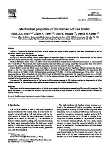
Temperature of Annealing: ll0°C
o.o
Beam Speed:
0
10
20
40
60
o.1
in/min.
120
Time of Annealing, Yin.
Fig. 19
Bffect of Annealing Time on Density of Speci•ena.
PVC Resin 353 ( fl
•
0.63) with 4.5 phr Mark-99.
180
59
In the la;t part of the study, specimens made with PVC resin of different
mole~ular
weights were ·tested on the Instron Tensile
Tester. The specimens contained different stabilizer contents of 3, 0
4.5, and 6 phr lfa·rk-99 and they were all annealed at 110 C for 20 minutes before testing. A medium beam speed of 0.1 in/min was used for the tests.
Fi~ure
20 shows true tensile yield stress increases
with nominal intrinsic viscosity which is a function of weight average molecular weight for all three different stabilizer contents. Like the yield
stres~,
figure 22 shows ultimate tensile strength also
increases rl th intrinsic viscosity of PVC. On the other hand, figure 21 s hows tensile :nodulus decreases with intri·nsic viscosity of the polymer.
60
9400
a~ · o phr l.lark-99 (I): (II): 4.5 phr Mark-99 (I II): 6.0 phr Mark-99
9200
.... ff
..
9000
1111
co
,..G.l ~
rn
.g
....c
Gl •f'4
>t
8800
&>
....c
.... 1111
1:::1 G.l
~
~
Gl
e
8600
~
E-4
~
8400
8200 0.6
. .. , 0. I
o.8
0.9
1.0
Nominal Intrinsic Viscosity
Fig. 20
yt
Effect of Weight Average Molecular Weight (Function
of Intri1sic Viscosity) on True Tensile Yield Stress. Beaa Speed: 0.1 in/min.
61
2.6
2.4
(I):
6.0 phr Mark-99
(II):
4.5 phr Mark-99
(III)~
a.o
phr Mark-99
~
Cf.l
ll-4
lO
I
0
.-4
2.2
>
cial grade
suspen~ion
polymerized. Manufactured and
suppl:l ed by Esso Chemical Canada of Sarnia, Ontario. The four 1lifferent grades which have been tested are: Nominal Intrinsic Viscosity ( '\.)
Stabilizer:
Esso llesin Grade
Lot No.
(dl/g)(Cyclo hexanone at 30°C)
353
70G051
o.~3
363
73G014
0.86
369
73G027
1.00
373
72D066
1.19
Bari1mjCadmium complex salt - trade name Yark-99. Manufactured by Argus Chemical Corporation of Brooklyn, New York. Supp: ied by Esso Chemical Canada of Sarnia, Ontario.
Lubricant:
Steari·c Acid. Supplied by Esso Chemical Canada, Sarnia, Ontario.
Testing Machines I.
Miniature lfiJcing and Injection Molder - Model CS-1831W. Manufactured ly Custom Sc :· entific Instruments, Inc. Whippany, N.J., U.S .A.
II.
Miniature Tensile Tester - Model CS-l83TE. llanufactured by Custom Scien ;ific Instruments, Inc. Whippany, N.J., U.S.A.
· III. Instron Tens i le
& Compression Tester- Yodel 'M'CL. Manufactured by
Instron Engineering Corporation, Canton, Mass. U.S.A.
94
Glossary
1)
Intrinsic V:lscosi ty:
Intrinsic viacosi ty
plottinlt the reduced viscosity,
(Yl]
is obtained by
(l'\_ -Y\._o)/rt_oC,
as a function
of ·conce11tration C, and extrapolating to infinite dilution. In this I!Xpression,
l\ o
Yl
is the viscosity of the solution and
is t h e viscosity of the solvent. The concentration is
usually 1!xpressed in grams per deciliter. For dilute solutione, the intrlnsic viscosity and molecular weight are related by the ltark·-Houwink equation: ~
(7)
,
where U
w
is the weight average molecular weight and K and a
are constants. Nakazawa and Uatsuo(
73
) reported that for PVC,
4 K is equ•:..l to 1.41 X 10- and a is euqal to 0.82 for intrinsic viecosities measured in cyclohexanone at 30
0
c.
The approximate 4
weight a·rerage molecular weight is in the range of 2 - 13 X 10 • 2)
Phr: Parts :ller hundred resin 'by weight.
3)
Percentage : Eaong~.~ion at Fracture:
Percentage increase in length
of the test section of the specimen at fracture from initial length. 'rhe length of the test section at· fracture is measured from the recording chart of tensile tester. 4)
Tensile Yod·o.lus:
In this study, tensile modulus is taken as the
elope of the initial straight line portion (within 50 ~ of the maximum :rield stress region) of the stress-strain curve.
IS)
Nominal 'f.enai : e Yield Stress: The loading force at yield point -- diYided by the initial cross-section area of the test section.
6)
True Tensile ;{ield Stress: by the
yield
ins · ~antaneous
poin· ~
The loading force at yield point divided
cross-section area of the test section at
• The instantaneous cross-eection area of the
specimen a ·!; yield point is determined fro• the amount of elongation the specim
T· ~lume
in this region.
Nominal Ultim~te Tensile Strength: The loading force at fracture diTided by. the initial cross-section area of the 'peeimen.
/