4 Mechanical properties of bioceramics M V SWAIN and L-H HE, University of Sydney, Australia
4.1
Introduction of basic definitions
4.1.1 Stress/strain The stress–strain relationship is the basic parameter to describe and evaluate a material. The quantitative treatments of deformation usually employ the concept of stress, which is the pressure at any point in a body submitted to a load and expressed as: s=
F A
4.1
where F is the force on the supporting area A. Because force, F, has direction, the stress, s, should be defined by not only in terms of its magnitude but also direction. From this point of view, stress can be divided into three types: tensile stress, compressive stress and shear stress. Material will experience deformation under certain stress. Strain quantifies the deformation of a body to stress and is defined as the ratio between the total deformation in one direction of a specimen and the length of the specimen in the same direction. Setting original length and increment of length as L and DL, separately, the strain, e, can be expressed as: e=
ΔL L
4.2
This equation does not consider the change of reference axes and is known as the nominal or engineering strain. More correctly, the true strain should be used, e=
L1
dL
ΔL
= ln ∫ L L0 L
4.3
This equation takes into account the change in the reference length L from its initial value L0 to its value L1 at each step of deformation. 78
Mechanical properties of bioceramics
79
Table 4.1 List of mechanical properties of some advanced bioceramics (Hench, 1998; Marshall et al., 2001; Guazzato et al., 2004; Yin et al., 2006) Bioceramics
Flexural strength (MPa)
Weibull modulus (m)
Elastic modulus (GPa)
Hardness (GPa)
Poisson’s ratio
Fracture toughness (MPa m1/2)
Cortical bone
50–150
–
7–30
–
–
2–12
Human tooth enamel
8–35
–
9–90
3.2–4.4
–
0.52–1.3
Human tooth dentin
31–104
–
11–20
0.25–0.8
–
2.8–3.1
Sintered hydroxyapatite
115–120
–
80–110
500 (HV)
–
1.0
Pressable ceramic (IPSEmpress I)
106 (17)
9.0
65 (1.5)
6.5 (0.4)
–
1.2 (0.14)
Pressable 303 (49) ceramic (IPSEmpress II)
8.0
90 (3.7)
5.5 (0.2)
–
3.0 (0.65)
Full sintered zirconia ceramic (Vita Zirkon)
840 (140)
7.5
220 (7.5)
12 (0.2)
0.33
7.4 (0.62)
Glass ceramic (MGC-fine)
–
–
70.5
4.15 (0.07)
–
1.04 (0.04)
Glassinfiltrated zirconia ceramic (Vita In-Ceram Zirconia)
476 (50)
10.5
240 (9)
11 (0.9)
0.26
4.9 (0.36)
Glass-infiltrated 440 (50) alumina ceramic (Vita In-Ceram Alumina)
9.5
265 (10)
11 (1.1)
0.25
3.6 (0.26)
Feldspathic porcelain (Vita D)
95 (20)
5.0
64
–
0.21
0.9
Feldspathic porcelain (Vita Alpha)
95 (15)
5.0
60
–
0.22
0.9
Alumina bioceramic (Al2O3 > 99.8%)
595
–
400
2300 (HV)
–
5–6
80
Bioceramics and their clinical applications
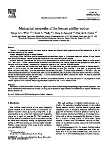
4.1 Indentation H–a/R (stress-strain) curve of human mature enamel compared with different dental ceramics and alloys.
When a given force (described by stress, s) is applied to a material, the associated deformation can be specified by the resulting strain, e. Therefore, the stress–strain curve has long been considered one of the most important parameters to evaluate material. With the curve, the deformation, which is strain, of any stress value can be predicted. In the materials science field, stress–strain curves of most materials have been determined using uniaxial tensile/compressive tests. The yield stress, elastic modulus and fracture force can all be read from the curve. But, because of the brittleness of bioceramics, it is hard to determine the stress– strain curve of ceramics using a similar method. Recently, with the development of the nanoindentation technique and associated theoretical contact mechanics, indentation stress–strain curves may be drawn with spherical indenters (Beghini et al., 2006; Herbert et al., 2001). Although there are still some difference between the uniaxial stress–strain curve and indentation stress–strain curve, the indentation stress–strain curve can still reflect both elastic and plastic responses of materials. Figure 4.1 illustrates the indentation stress–strain curves of different dental ceramics and compares them with those of enamel and metallic alloys. This kind of comparison provides a new way to rank and select the biomaterials.
4.1.2 Elastic modulus From Hooke’s law, we know that, within the elastic range, the strain has a linear relationship with stress. And the term Hookean behavior is used to
Mechanical properties of bioceramics
81
describe the usual case in which a given strain component varies linearly with stress in components (Guy, 1972). From this point of view, elastic modulus is known as the ratio of stress to strain below the proportional limit. It represents the magnitude of the interatomic stiffness of a material within the elastic range when tensile or compressive forces are applied. It is also an indication of the amount of reversible deformation that will occur in a structure when a load is applied. From the definition of stress and strain, elastic modulus can be derived as follows: E=
F /A FL s = = e ΔL/L ΔLA
4.4
Elastic modulus is a basic parameter to describe the material. Not only researchers but also clinical practitioners are interested in this value, because it may assist with the selection of restorative biomaterials with more similar deformable properties to those of the material it is replacing. For force-bearing structures, a high elastic modulus is often required to limit the deflection on loading and still returns to its original shape after being stressed. It has been reported that increasing the elastic modulus of a supporting core structure of a dental restorative material might be a way of improving the fracture resistance of all-ceramic dental crown/bridge structures (Lee and Wilson, 2000). Several methods have been developed to measure the elastic modulus of materials. Most common are bending tests, nanoindentation measurement and nondestructive methods. Bending tests The elastic modulus of ceramics is usually determined by bending tests, because deflection is more easily measured than very small tensile or compressive elongations. For three-point bending, elastic modulus can be calculated by: E=
Fl 3 4bh3 y
4.5
where F is loading force and y is deflection of the sample; l is the distance between the supports, b and h are width and height of the cross-section, respectively. For four-point bending, elastic modulus is equal to: E=
3Fl02 l1 4bh3 y
4.6
where F is loading force and y is deflection of the sample; l0 is the distance between the inner load points, l1 is the distance between the inner and outer
82
Bioceramics and their clinical applications
supports and b and h are width and height of the cross-section, respectively. Nanoindentation tests Based on Snedden’s theoretical work (Snedden, 1965), Oliver and Pharr developed a method of measuring elastic modulus of a material with a nanoindentation machine (Oliver and Pharr, 1992). The Berkovich indenter, a three-sided pyramid-shaped diamond indenter, is usually used to do the measurement. The effective elastic modulus, E*, can be calculated by fitting the unloading indentation force–displacement curve (see Fig. 4.2): E* =
1 dP 1 b dh 2
p A
4.7
in which dP/dh is the stiffness at the beginning of unloading, A is the contact area and b is a correction factor (1.034 for Berkovich indenter). The unloading stiffness, dP/dh, can be calculated from the derivative of the initial unloading curve. The effective elastic modulus is determined by the elastic modulus and Poisson’s ratio (which is the ratio of transverse contraction strain to longitudinal extension strain in the direction of stretching force) of sample and indenter based upon the following relationship: (1 −ν 2 ) (1 −ν ′2 ) 1 = + E* E E′
4.8
4.2 Schematic diagram of indentation force–displacement curve. (ht is total penetration depth).
Mechanical properties of bioceramics
83
Here, E, E′ and n, n′ are elastic modulus and Poisson’s ratio of the sample and indenter, respectively. Knowledge of the elastic modulus and Poisson’s ratio of diamond, which are ∼1000 GPa and 0.007, means that the elastic modulus of the sample can be calculated. This method is of high precision and is convenient; it can be used to measure micro-scale samples. Sometimes, because of the size limit of bioceramic materials, especially those porous scaffold materials, it is difficult to measure the real elastic modulus of the material without the influence of pores inside. Under this condition, the nanoindentation technique has an advantage. Nondestructive methods Nondestructive methods on elastic modulus measurement are also named dynamic methods (ASTM, 1990), which include: frequency of oscillation of the rod method, ultrasonic pulse transit-time method, resonant ultrasound spectroscopy, free oscillation torsion pendulum and impulse excitation of vibration. Although usually specific equipment is required, these nondestructive methods have become widely popular for elastic modulus measurement because of their simplicity and repeatability and because they are nondestructive. Knowledge of the elastic modulus is clinically relevant, because it may assist with the selection of a restorative material with similar deformable properties to those of the material it is replacing, e.g. bone or enamel. Bioceramics with comparable elastic properties to those of nature tissues can decrease the stress concentration at the bonded material–tissue interface, as for instance with occlusal loads on restored teeth and marginal bonding.
4.1.3 Hardness Hardness may be the most widely used parameter for evaluating and comparing materials. The hardness of a material usually is considered as a measure of the resistance to permanent indentation (Boyer, 1987). The principal purpose of the hardness test is to determine the suitability of a material, or the particular treatment to which the material has been subjected. The ease with which the hardness test can be applied has made it the most common method of inspection for most materials. The general procedure for hardness assessment can be summarized as: a standardized force or weight is applied to an indenter pressing into the surface of a material to create a symmetrical shaped indentation (residual impression). The dimensions of the indentation (area, depth or width) are measured at a microscopic level, and entered in a specific hardness formula
84
Bioceramics and their clinical applications
according to the type of tests. Therefore, the hardness value is different for different test methods. The most common used hardness test methods include: Brinell hardness test, Knoop hardness test, Vickers hardness test and nanoindentation hardness test. Because of the size limit of bioceramic samples, micro- and nano-hardness tests may be the best choices. Diamond Knoop and Vickers indenters are usually chosen in microhardness tests, while the Berkovich indenter is the most common one for nano-hardness tests. In Knoop and Vickers microhardness testing, the hardness value is determined by measuring the size of the unrecovered indentation with a microscope and using established formulas. Vickers hardness is calculated as: HV =
1.8544 P , d2
4.9
where P is load (kg) and d is mean diagonal of the indentation (mm). Knoop hardness has the equation of, HK =
P , 0.07028l 2
4.10
where P is load (kg) and l is the measured length of the long diagonal (mm). For nano-hardness testing, the hardness value is based on the definition of hardness, which is, H=
P . A
4.11
Here, load P is controlled by the machine and contact area A is calculated from penetration depth with a geometrical relationship. For a Berkovich indenter, the contact area has the relationship with contact depth is A = 24.5h2p although the tip needs to be calibrated for very shallow impression depths. Oliver and Pharr (1992) also proved the relationship between hp and ht as: hp = ht − ε
P . dP/dh
4.12
For Berkovich indenter, ε = 0.75. Therefore, from the force-displacement curve (Fig. 4.2), the hardness of the material can also be calculated using equations 4.11 and 4.12.
4.1.4 Fracture strength Strength can be defined as the maximum tensile stresses that a material can endure before fracture occurs. It might also be defined as force per unit
Mechanical properties of bioceramics
85
area required to initiate and propagate a crack to the fracture point. Strength is an important mechanical property to evaluate the performance of brittle materials such as bioceramics. The inability of ceramics to reduce the tensile stresses at the tip of the cracks by deformation in an inelastic manner explains why they are much weaker in tension rather than in compression and also why bioceramics normally fail in areas of tensile stresses. Therefore, tensile strength is considered more significant than compressive strength in the brittle material field. Several methods have been introduced to measure the tensile strength of materials. They include bending flexural tests and biaxial flexural strength tests. For the three-point bending flexural test, by following ASTM C 1161, flexural strength, sF, can be calculated with:
σF =
3Pl , 2bd 2
4.13
where P is breaking load (N), l is test span (m), b and d are width and thickness of the specimen respectively. The corners of the specimens need to be trimmed to minimize the failure probability from corner cracks because of such cracks are more deleterious to strength than surface cracks. The calculation of biaxial flexural strength, sF, can be found in ASTM F 394-78: sF = −0.2387P(X − Y)/d2, X = (1 + n)ln(B/C)2 + [(1 − n)/2](B/C)2,
4.14
Y = (1 + n)[1 + ln(A/C)2] + (1 − n)(A/C)2, where P is breaking load (N), d is specimen thickness, n is Poisson’s ratio, A is the radius of support circle, B is the radius of the tip of piston and C is the radius of specimen disk. The recommended crosshead speed for these flexural strength tests is 0.5 mm/min. This speed may influence the results because of the sub-critical crack propagation, which will be discussed later in this chapter. To describe the scatter of strength because of the nature of the flaws in the sample, Weibull (1951) suggested an empirical distribution function. The influence of specimen volume was incorporated into strength appraisal where the concept of failure probability, F, is used to describe the variability in strength of brittle materials. With this function, the failure probability of a specimen at any applied stress can be predicted. Too high failure probability should be avoided by changing the design or improving the material selected.
86
Bioceramics and their clinical applications
The empirical method to describe the strength distribution of brittle material is named the Weibull approach. This approach is based on a ‘weakest link’ idea, in which the strength of the body depends on the strength of the weakest unit inside. The Weibull approach assumes a simple power-law stress function and has three-parameter distribution and twoparameter distribution forms. The three-parameter distribution of failure probability, F, under tensile stress, s, has the expression:
(
σ − σ min ⎡ F = 1 − exp ⎢ − ∫ σ0 ⎣ V
)
m
⎤ dV ⎥ , ⎦
4.15
where s0 is the characteristic strength, m is the Weibull modulus and smin is the minimum strength. The characteristic strength, s0, can be interpreted as the uniaxial strength of a body with unit volume at a failure probability of 0.632. The Weibull modulus characterizes the distribution or variability of strength. Lower m means greater scatter of the strength, while higher m suggests better reliability and safety. More frequently, two-parameter distribution is used by assuming smin = 0. Thus, Eq. (4.15) can be simplified as: ln ln
( 1 −1F ) = m ln σ
max
− m ln σ *0 ,
4.16
in which smax is the maximum applied stress and s*0 = s0(LFV)1/m. LF is named the loading factor, which reflects the stress distribution in the body. Similar to s0, s*0 represents the specific characteristic strength of a body at F = 0.632 for particular V and LF. Based on this equation, the Weibull modulus of the material can be read from the slope of regression line of lnln(1/(1 − F)) versus lnsmax. For brittle bioceramics, flaws, which influence the scatter of strength and reliability of the material, are usually introduced during the fabrication processes. Different techniques may produce different numbers of flaws and thus influence the reliability of the structure. A comparative research (Tinschert et al., 2000) on dental ceramics verified this assumption, in which the results indicated that industrially prepared ceramics are more structurally reliable than dental laboratory-prepared ceramics for dental applications. This may be because materials produced in a dental laboratory experience more critical processes such as thermal sintering cycles and water and binder phases removal while heating and all of these processes may introduce more flaws into the structure. In conclusion, from the point of view of fracture strength, bioceramics, long-term functioning materials in critical environments, need not only high strength, but, more importantly, high reliability (high Weibull modulus).
Mechanical properties of bioceramics
87
4.1.5 Fracture toughness Since crack propagation and subsequent fracture is known to be the major problem that leads to ultimate structural failure, it is important to know the threshold condition of crack propagation. Therefore, fracture mechanics concepts have been applied to characterise the criteria of crack propagation of brittle materials such as bioceramics. The strength of a brittle material, sa, is related to the critical stress intensity factor, Kc, at a crack tip can be calculated with the following equation: K = Yσ a c ,
4.17
in which c is the radius of a crack and Y is a geometrical factor. Irwin (1958) analyzed the crack propagation procedure from a critical stress point of view and concluded the criteria of crack propagation, which is stress field intensity, K, of crack tip should be bigger than a certain value Kc. Kc is critical stress intensity level at which a given flaw starts growing. In mode I (uniaxial tension) crack model, this threshold value is also named as the fracture toughness, KIc, which indicates the ability of a material to resist crack propagation and its consequent catastrophic failure. The definition of fracture toughness in ASTM E-24 is: the resistance to crack propagation under plain strain conditions, which means strain value of crack tip should be kept constant while crack start propagating. Fracture toughness is one of the most important mechanical properties that delineate the fracture behavior of a specific material. It has gained wide acceptance as a technique suitable for the assessment of a ceramic material’s ability to resist crack propagation. In the biomaterials field, fracture toughness values may help us to evaluate the serviceability, long-term clinical success and performance of the brittle materials. It has been proven that materials with high fracture toughness demonstrate improved clinical performance and reliability than low fracture toughness one (Fischer and Marx, 2002). Various methods and techniques have been used for the determination of the fracture toughness of brittle materials. These methods can be divided into two main groups. One comprises traditional notched and pre-cracked sample tests, e.g. compact tension, double cantilever beam, single-edge notched beam, single-edge pre-cracked beam and chevron notch. Another includes indentation tests such as indentation fracture and indentation strength. The detailed schedules and calculation of each method can be found in relative test handbooks or fracture mechanism textbooks (Anderson, 1995; ASTM, 1999).
88
Bioceramics and their clinical applications
4.1.6 Fatigue The failure of a material due to repeated stressing is known as fatigue (Guy, 1972). It is an important concept in the design and operation of most structures and has long been used in metal material and structure design fields. Because of the brittleness of ceramics, fatigue of ceramic, especially bioceramics, is still a new and difficult field to explore. Most bioceramics experience cyclic loads during their serving life. Therefore, anti-fatigue ability should be taken into serious consideration of the material development and structure design. Using a finite element analysis, Brockenbrough and Suresh (1987) showed that when the cyclic stress leads to permanent strains, the resulting residual stresses that arise in the matrix material in the vicinity of a stress concentration are distinctly different from those induced under monotonic loading conditions. This effect of permanent strains causes a mode of failure that is unique to cyclic loading conditions. Under cyclic loading, microcracks may initiate at grain boundaries and interphase regions, and along the interfaces between the matrix and the reinforcement. Several processes may contribute to the irreversible deformation and fatigue of brittle materials relating to such microcracks, which are (Suresh, 1998): • • • • •
frictional sliding of the mating surfaces of the microcracks; progressive wear and breakage of the bridging ligaments connecting the mating surfaces of cracks; wedging of debris particles into the mating surfaces of cracks; releasing of residual stresses at grain boundaries and interfaces; stress-induced shear or dilatational transformations such as mechanical twins or martensitic lamellae.
In the metal area, the fatigue properties of material can be described by crack propagation curve, da/dN-ΔK curve. Paris and coworkers (Paris and Erdogan, 1963; Paris et al., 1961) showed that in this curve, the fatigue crack growth increment da/dN has an empirical power law relationship with the stress intensity factor range ΔK as follows: da = C ⋅ΔK n , dN
4.18
where C and n are scaling constants, which are influenced by the material microstructure, environment and load ratio, R. A study of dental feldspathic porcelain with an indentation technique generated the results of 4 and 2 × 10⁻⁶ for n and C, respectively (White, 1993). This study indicated that the relationship for metals could also be used in the ceramic area to describe the fatigue property of bioceramics.
Mechanical properties of bioceramics
89
Another practical method to evaluate the influence of fatigue on bioceramics is the cyclic contact-loading test. Usually, a Hertzian or ballinduced contact mode was chosen in these tests. The investigation conducted by Jung et al. (2000) on four different kinds of dental ceramics showed that after 106 contact cycles with loads from 200 to 3000 N, strength of all samples degraded. Moreover, after a very large number of contact cycles, all materials showed an abrupt transition in damage mode which is not observed in a comparative static loading test. These results indicate that cyclic loading may add additional damage to a bioceramic material and its structure. Under functional loading conditions, this fatigue property of bioceramics should be included into our considerations of material selection and structure design.
4.2
Reinforcement of bioceramics and its significance
The in vivo conditions of bioceramic structures are critical. High localised stresses on certain points of the structure and the surrounding erosion environment all ask for high mechanical properties of bioceramics. At this stage, the hardness and fracture strength of most bioceramics can meet the need to serve as substitute structures such as dental crown/bridge and artificial joints. The major problem is how to improve the fracture toughness of the material to resist crack propagation under cyclic loads so that the life and reliability of bioceramic medical structures can be guaranteed. The basic mechanisms of ceramic reinforcement (Evans, 1984; Green, 1998), such as crack deflection, bridging and phase transformation will be introduced briefly in this section.
4.2.1 Toughening due to crack deflection As the crack extends, the crack path will change when the tip of the crack meets a second phase in the material such as reinforcement particles. In addition there are often residual stresses associated with such particles as they have a different coefficient of thermal expansion and different elastic moduli values from the matrix. Considerably more energy will be used for the crack tip to pass through the particle. Therefore, a crack tip will change its direction to avoid these particles; more energy is required to change the crack direction (Fig. 4.3).
4.2.2 Toughing due to the bridging of the second phase reinforcement particles The reinforcement particles behind the crack tip can also act as ‘bridges’ between two surfaces of a crack. As these particles are embedded into both
Bioceramics and their clinical applications
Crack
Re in par force ticle me nt
90
4.3 Schematic diagram of crack deflection due to reinforcement particles.
Reinforcement particle
Crack tip
4.4 Schematic diagram of bridging behind the crack tip.
surfaces of the crack, which reduces the stress intensity at the crack tip and further extension of the crack requires addition external loading to break or extract these ‘bridging’ particles first (Fig. 4.4).
4.2.3 Toughening due to stress-induced phase transformation of material The incorporation or manufacture of a material from a metastable phase material provides for stress-induced transformation about the crack tip of such a material to impart toughening. Volume dilation associated with such a localized phase transformation can decrease the effective tensile stresses at the tip of crack by adding localized compressive stresses (Fig. 4.5). The above-mentioned mechanisms build a stress shielded area in the crack processing zone and reduce the stresses of crack tip dramatically. These kinds of toughening effect can be summarized as R-curve behavior of the material. R-curve behavior can be depicted as the energy dissipation rate during fracture can increase as the crack extends (Green, 1998). It has
Mechanical properties of bioceramics
91
4.5 Schematic diagram of stress-induced phase transformation at the tip of crack.
positive influence on the strength, scatter-in-strength and long-term strength behavior of the material. Therefore, for bioceramics, R-curve behavior is a desirable mechanical effect to resist crack propagation and structural failure. Tests with indentation flexure strength method on different dental ceramics showed that most toughened ceramic materials exhibited a rising R-curve with crack extension and this behavior was more pronounced for the high strength materials (Fischer et al., 2002). Zirconia-based ceramics, which have been used in the medical field for several years as core material of dental all-ceramic crown/bridge, artificial joints and other medical devices (Piconi and Maccauro, 1999), are a good example of these transformation toughening mechanisms. The remarkable mechanical properties of zirconia are mainly due to the tetragonal to monoclinic (t–m) phase transformation. The t–m transformation, which can be induced by external stresses, such as the stresses at the tip of cracks, results in a 4% increase of volume that causes localized compressive stresses to develop about the crack tip. It is this clamping constraint about the crack tip that must be overcome in order for the crack to propagate, explaining the increased fracture toughness of zirconia compared with other ceramics. Transformation toughening can occur when the zirconia particles are in the metastable tetragonal form, and on the verge of transformation. The metastability of the transformation is dependent on the composition, size, shape of the zirconia particles, the type and amount of the stabilizing oxides, the interaction of zirconia with other phases and the processing. Furthermore, transformation toughening is not the only mechanism acting in zirconiabased ceramics. Micro-crack toughening, contact shielding and crack deflection can also contribute, to a different degree, to the toughening of the ceramic (Guazzato et al., 2004).
92
Bioceramics and their clinical applications
4.3
The effects of flaws and environment on mechanical properties
No material block or structure is perfect. Brittle solids contain a population of small microscopic flaws named Griffith flaws. The presence of these flaws can cause marked reductions in fracture strength. Defects such as cracks, pores and grain boundary defects, are usually generated during the processing procedures such as cutting, pressing or sintering. These defects serve as potential sites for the nucleation of a dominant crack. The functioning environments of most bioceramic structures are also critical. These structures experience chemical erosion, thermal or mechanical cycles, contact forces and wear. All of these factors will introduce Griffith flaws and lower the mechanical properties and life of the structure. The essential problem that influences the mechanical properties of bioceramic is the presence of defects or cracks. As brittle material, bioceramics are easily affected by flaws and the influences of such cracks on mechanical properties are controlled by two aspects, which are crack initiation and crack propagation.
4.3.1 Basic description of fracture mechanisms To clarify stress concentration and fracture of bioceramics, we should start the discussion from the concept of the theoretical cleavage strength and fracture criterion. In atomic scale, from the consideration of the interatomic potential, the stress is expected to increase initially as a function of the interplanar spacing d. At a certain point, the stress will reach a maximum value, after which, with the increasing of interplanar spacing d, stress decreases. This maximum stress is termed the theoretical cleavage stress, sth (Green, 1998). the theoretical cleavage strength is found to be a material property and can be expressed as:
σ th =
Eγ , d0
4.19
where E is elastic modulus, g is the surface energy and d0 is the equilibrium interplanar spacing (under zero stress). Stress concentration can be described as stress at the tip of defect or crack that is much bigger than the applied stress. We consider the crack in an infinite plate subject to uniaxial tension (Fig. 4.6) as an elliptical hole and the elastic solution can be expressed as (Green, 1998):
σ tip = σ (1 + 2 c/ρ ) ≈ 2σ c/ρ ,
4.20
in which s is uniaxial tensile stress, c is half the length of the defect and r is the radius of curvature at the ends of the major axis of the defect.
Mechanical properties of bioceramics
93
σ
σtip 2c
σtip
σ
4.6 An internal defect in a large plate under the action of a uniaxial tensile stress.
From this equation, if r approaches atomic dimensions, the stress concentrated at the tip of crack, stip, would become very large. This phenomenon is termed the stress concentration of defects. The simplest method to evaluate fracture should be to equate the highest tensile stress associated with a crack, stip, to the theoretical cleavage stress, sth. Fracture stress, sf, can be predicted by combining Eqs. (4.19) and (4.20). But for atomically sharp cracks this method may not be appropriate, because the stresses at the crack tip would be so high that the stress field is not expected to be linear elastic. Moreover, at these dimensions, treating the material as a continuum has limitations. Thus, a new approach is needed to resolve the problem. Fortunately, in a pioneering work, Griffith (1920) postulated that materials already contain (pre-existing) cracks and it is the stress concentration associated with these cracks that gives strengths less than the theoretical cleavage stress. By considering the condition of a cracked body in an isolated system under the action of applied tractions with the energy method, Griffith deduced the famous equation of the critical stress for crack extension (the fracture stress sf):
σf =
2Eγ . πc
4.21
This equation is commonly termed the Griffith equation in which E is elastic modulus, g is the surface energy and c is initial crack size. In this work, Griffith approved both theoretically and experimentally that fracture stress – is inversely proportional to √c. All the above theoretical analysis indicates that the strength of a bioceramic and its structure may be influenced by cracks in it. Therefore, to understand the mechanical evaluation of bioceramic structures, it is
94
Bioceramics and their clinical applications
necessary to learn the performance of cracks first, including the initialization and propagation.
4.3.2 Crack initialization due to flaws and environment Different flaws and factors, such as pores and grain boundary defects, thermal cycles, impact force, and wear, will cause cracks. Pores The mechanical model described in Fig. 4.6 and Eq. (4.20) can also be used to explain the effects of pores and grain boundary defects. In short, pores and grain boundary defects will lead to stress concentration thereby making cracks easier to initiate and propagate. Pores inside the material are usually generated during the laboratory manufacturing procedure. Considering dental porcelain-fused-to-metal (PFM) techniques as a good example, the technician mixes the ceramic powder with water to form a paste to facilitate the crown/bridge build-up. During firing and ceramic powder sintering processes, water will evaporate, making it virtually impossible to avoid the generation of pores. Research showed that porosity of dental porcelains was sensitive to the powder/liquid ratio (Zhang et al., 2004), which means different technician-based procedures will lead to a range of the resultant mechanical properties for same material. Recently, more high-strength all-ceramic materials have been introduced into the dental field, not only because of their high strength, but also because they are all prefabricated, which means there are fewer pores and other defects. Some other bioceramic materials, especially those that act as scaffolds for tissue engineering, in contrast, need different size of pores to provide space for cells and other tissues. These pores will definitely decrease the strength of the material. Research has indicated that different size and shape of pores influenced the mechanical strength of the material (Liu, 1996). Therefore, it is still a challenge to optimize such porous bioceramic structures to meet the needs of both mechanical and biological requirements. Thermal cycles Bioceramic structures usually function at body temperature environment and the thermal cycle may be negligible under this condition. But they may experience critical thermal cycles during manufacture processes. Take dental porcelain fused to metal with a slight difference on thermal and elastic properties as an example. During crown/bridge construction, the materials need to be heated to a temperature of nearly 900 °C, which is much higher
Mechanical properties of bioceramics
95
than the glass transition point of the porcelain. If the heating or cooling speed cannot be well controlled, such thermal cycles may introduce defects into the structure because of the presence of the thermal residual stresses. Cyclic/impact contact forces The contact between the bioceramics appliances and opposing structures can be normalised as the standard Hertzian contact, which is the ball-on-flat contact (Fig. 4.7). This situation is very common in dental and orthopedic loading situations involving bioceramics. This kind of Hertzian contact has been well documented (Lawn, 1998). The average contact pressure P0 is:
( 34Ek ) π1 ( rP ) . 2/3
P0 =
1/3
4.22
2
The maximum tensile stress in the specimen occurs at the contact circle:
σm =
1 (1 − 2ν )P0 . 2
4.23
The maximum shear stress is located along the contact axis at a depth ≈0.5a below the surface: tm = 0.48P0
4.24
Under impact conditions, the initial contact motion is much bigger than static contact because initial contact energy includes not only static load
P Cone crack Plastic area Specimen Radial crack
Substrate
4.7 Typical Hertzian contact model.
96
Bioceramics and their clinical applications
but also kinetic energy. The maximum tensile and shear stresses may be bigger than the equivalent static contact condition. If the tensile stresses about the contact area along with the presence of a defect result in the localized stress intensity factor exceeding the KIc of a material, a crack will initiate. The extent of crack propagation is limited as the diminishing stress field with distance from the contact area results in a crack arrest rather than unstable propagation through the indented structure. Under cyclic contact loading, while the cone cracks and radial cracks may propagate under the cyclic force, the damage of the material in the plastic zone may accumulate and lead to the deterioration of the strength property of the specimen. This has been demonstrated by cyclic contact research on ceramics (Kim et al., 1999), in which two models of damage are observed. One is the conventional tensile-driven cone cracking (‘brittle’ mode) and the other is shear-driven microdamage accumulation (‘quasi-plastic’ mode). Strength losses are caused by the cone cracks and subsequent more deleterious reductions are caused by the radial cracks. Another investigation of a coarse-grained alumina (Fett et al., 2005) showed that delayed failure in bar cyclic contact fatigue loading tests is caused by a reduction of the friction between the crack surfaces due to cyclic loading and by a related increase of the effective stress intensity factor until the fracture toughness of the material is reached. Meanwhile, the processes about the irreversible fatigue damage mentioned above may also play roles in such cyclic contact damage. Wear Some bioceramic structures such as denture and artificial joints have sliding contact with opposing structures. Under this condition, surface wear is an unavoidable problem for these structures. Wear will produce cracks and surface fracture by different mechanisms, e.g. abrasive wear, fatigue wear and corrosive wear (Mair et al., 1996). These cracks may propagate at a latter time under functional stresses. From this point of view, wear is an important factor to reduce the mechanical properties of structures. Terheci has mentioned that surface fatigue during wear maybe an important reason for the surface destruction of ceramic materials (Terheci, 1998). Surface fatigue wear plays an important role in the wear of the orthopedic and dental bioceramics and other dental and natural materials they are in contact with. Mashal also indicated that the main mechanism involved in the wear of ceramic is the detachment of a particle from a surface, which is usually associated with crack propagation and fracture (Mashal, 1995). The main process of dental material surface contact damage, especially the wear of brittle and/or compound material, is surface fatigue
Mechanical properties of bioceramics
97
generation and accumulation of residual stress, crack initiation and propagation followed by particle detachment. Contact mechanics analysis in Fig. 4.8 shows the stress distribution near sliding contact area. With the repeated change of sliding direction, the cyclic changing tangential/compressive stresses within the contact area are the main reasons for the surface fatigue, residual stress and crack propagation. Figure 4.9 illustrates the subsurface damage in a 3-D manner. Wear properties of bioceramics in the form of various appliances have been well investigated (Bolton, 2002; Mair et al., 1996; Teoh, 2000; Teoh
Sliding direction
P
Pure tangential compression area
Pure tangential traction area
Pure tangential force
Pure tangential force Traction plus normal loading area
Compression plus normal loading area
Compound force
4.8 Two-dimensional schematic illustrating stress field distribution during local sliding contact.
Load
Plastic groove Lateral crack
Plastically deformed region
Residual forces
Lateral crack
Residual forces
Radial crack
4.9 Three-dimensional schematic representation of the formation of cracks by sliding contact with sphere particles.
98
Bioceramics and their clinical applications
et al., 1998; Willmann, 2001). For those structures where contact occurs directly with another part made of similar materials, such as artificial joints, a reduction of the wear rate, surface destruction and wear debris of the whole contact system is anticipated. For structures in contact with natural tissues, such as teeth, we would like the material to have similar or even slightly greater wear rate than the natural tissue to protect the opposite tissue from excessive wear and destruction.
4.3.3 Crack propagation due to flaws and environment The crack propagation of bioceramics in vivo is mainly due to subcritical crack propagation by chemical erosion and stress. It is not always the case that failure only occurs when KI ≥ KIc. Crack propagation that occurs at a KI which is lower than KIc is usually called subcritical crack propagation. Several mechanisms may lead to subcritical crack propagation, but the focus of research has concentrated on stress-induced corrosion. This behavior has been extensively studied in silicate glasses but it can also occur in many polycrystalline ceramics (Green, 1998). The stress corrosion on ceramic can be explained by Fig. 4.10. It is well known that the silicon dioxide framework is sensitive to water molecules. As shown in Fig. 4.10, an H2O molecule upon entering the crack tip region reacts and finally breaks the bonds of silicon dioxide at the crack tip. Other environmental species may also react at the crack tip and cause the bond breakage in a similar form. Because of this kind of stress erosion reaction, cracks at the surface of ceramic structures may propagate at a lower critical stress intensity factor in an aqueous environment. Therefore, the response of ceramic to stress corrosion becomes an important question to determine whether crack propagation of ceramic will occur in an erosive environment. Figure 4.11 is a typical response of crack propagation of ceramic under an aqueous erosive environment. There are three distinct regions of crack velocity, n, as a function of stress intensity factor K. Initially, when the stress intensity factor reaches a threshold value, K0I, subcritical crack propagation becomes
Si Si H
O
Si
O H
O Si
O O
Si
H
O
O
Si Si
O Si
OH
O
H O Si
Si O
O
O Si
OH Si
Si O
O
Si
O
4.10 Schematic of H2O reacting with SiO2 at the crack tip and leading to crack propagation.
99
Inv
Mechanical properties of bioceramics
III II I
Kl 0
Klc
InΔK
4.11 Schematic trend of crack velocity, n, during subcritical crack growth as a function of stress intensity factor, K.
activated. After that, crack velocity, n, increases rapidly with the growing K value (region I). This region is usually related to the stress-assisted chemical reaction-driven crack growth. At higher stress intensity levels the crack velocity enters a plateau region (region II), in which the stress intensity factor has little influence on the velocity. This is because the transportation speed of chemical erosive species limits the propagation of the crack tip. Eventually the crack tip stress intensity levels reach the fracture toughness KIc of the material (region III), resulting in catastrophic crack propagation. With the knowledge of subcritical crack propagation, consideration of the structural reliability and service longevity in service are possible. Regarding regions II and III as high-speed crack propagation mechanisms the lifetime of the material is mainly dependent upon crack propagation of region I. Therefore, most researches were concentrated on the region I behaviors of material. Evans (1972) summarized the n–K relationship of region I in an empirical equation: n = AKnI,
4.25
in which A and n are constants and named as subcritical crack growth parameters. Large numbers of experiments have shown that this equation can satisfactorily describe the region I behavior of ceramic material. n is also known as the subcritical crack growth index which depends only on material and environment. This parameter reflects the influence of environment on material. A smaller n value indicates the environment (erosive species) is very sensitive for the material and subcritical crack may grow quickly.
100
Bioceramics and their clinical applications
Because of the importance of subcritical crack growth in the life prediction of a structure, several methods have developed to study this behavior of material. In general, all methods can be divided into two categories: direct measurement methods and indirect measurement methods; each has its advantages as well as disadvantages. Direct methods need pre-cracked samples and can observe the details of crack propagation while indirect methods usually use intact samples and can simulate nature crack propagation and destroy better. Double torsion (DT) and double cantilever beam (DCB) samples are mostly used in direct measurements and with some fracture mechanical analysis, the n–k relationship can be determined. By considering the basic equation of stress intensity factor (Eq. 4.17) and subcritical crack propagation equation (Eq. 4.25), for any stress cycle s(t), the fracture strength sF has a relationship with stress rate ds/dt as: ln σ F =
{
( )}.
1 dσ ln[ B(n + 1)S1n − 2 ] + ln n+1 dt
4.26
SI is the initial inert strength, n is subcritical crack growth index and 2 K 2 IC B= . By changing the stress rate, subcritical crack growth (n − 2)Y 2 v0 index, n, can be obtained from the slope [1/(n + 1)] of lnsF − lnds/dt curve. This method is also termed as the dynamic fatigue method. With the n value, the failure time, tf, of the material under certain stress sA can be predicted as: tf =
BSI n −2 . σ An
4.27
This is the base of life prediction of bioceramic structures. Similar methods have been summarised and used in bioceramic evaluations (Barinov et al., 1998; Lohbauer et al., 2002; Qiao et al., 2002; Ritter, 1995).
4.4
Lifetime prediction and proof test
Lifetime prediction of different structures has long been a goal for materials engineers. Several methods have been developed to predict the life of engineering structures and been very successful in metal structure area. Numerous cyclic stress–life (S-N) curves of different metallic materials have been drawn and been used in life prediction. The basic life prediction processes are listed in Fig. 4.12. In brittle material area, because of the complexity of cyclic damage mechanisms and fast catastrophic crack propagation when KI ≥ KIc, life prediction becomes difficult and unpredictable. Few S-N curves are available
Mechanical properties of bioceramics Fatigue properties of the material (e.g. S-N curve)
101
Structure responses under cyclic loadings
Fatigue damage cumulative theories
Predicted life of the structure
4.12 Schematic flowchart of structure life prediction analysis procedures.
at this stage, because of the large scatter of test data. Moreover, most damage cumulative theories developed from metallic materials are not suitable in a brittle material field. Therefore, life prediction of brittle structures is mainly based on the knowledge of subcritical crack growth mentioned above. Several efforts have been developed in this area (Fischer et al., 2003; Lohbauer et al., 2002; Seidelmann et al., 1982). The general method to evaluate the lifetime of bioceramic structures is to measure the subcritical crack growth parameters (dynamic fatigue parameters) and calculate the lifetime with the help of finite element technique. The CARES/ Life (Ceramic Analysis and Reliability Evaluation of Structure Life Prediction) software (NASA Lewis Research Center, Cleveland, OH, USA) is such a software package to predict the reliability and life of structures made from advanced ceramics and other brittle materials such as glass, graphite and inter-metallics. The CARES/Life software links with several commercially available finite element analysis packages, including ANSYS® and ABAQUS®. It accounts for the phenomenon of subcritical crack growth (SCG) by utilising the power law relationship (Eq. 4.25), as well as other algorithms, and can predict the failure of structure by simulating thermomechanical and/or proof test loading such as the Weibull modulus. Medical appliance systems must be safe and, show excellent reliability and good biocompatibility during its long-term in vivo service. But, because of the unavoidable nature of flaws and cracks, some new bioceramic medical appliances may fail shortly after the implantation. Therefore, the proof test was designed to reveal those structures with microscopic defects and reduce the failure probability of the implanted appliances. By definition, a proof test refers to a predetermined and specific test designed to verify the suitability of certain structures for the intended purpose. The common procedure of proof test is to subject every product to a proof load sP, which is larger than the maximum physiological load smax in vivo. The ratio of the
102
Bioceramics and their clinical applications
proof load to the maximum load is defined as the safety factor. Those parts that survive the proof test without any fracture or crack initiation/ propagation may be regarded as suitable and have significantly reduced failure probability under physiological loads. Several proof test methods have been developed to test different medical appliances. Now, before entering the market, most medical appliances, such as artificial joint systems and heart pumps, need to pass proof tests to meet the requirement of the US Food and Drug Administration (FDA). In short, the proof test rejects defective products in the production line before being implanted into human body, and reduce the clinical failure of artificial parts.
4.5
Summary
Because of the excellent biocompatibility, matching shade, good anticorrosion ability, bioceramics are ever more widely being used in the biomedical field. Most of these bioceramic appliances need to bear forces during their lives. Therefore, the mechanical properties became the most important factors to rank and select proper material. With the rapid development of modern material science and technology, more and more high-strength, high-toughness bioceramics have been developed and introduced into biomedical usage. The ever-more critical evaluation of existing and new bioceramic appliances will greatly increase the security and confidence of the medical usage of these materials. In conclusion, in a mechanical point of view, a bioceramic and its appliances need to meet the following standards: • • • •
similar elastic modulus, hardness and stress–strain relationship as the natural tissue; high fracture toughness and subcritical crack growth index; good wear resistance and minimal fatigue crack growth susceptibility; all bioceramic appliances should undergo proper designed proof test to guarantee their quality.
4.6
References
ASTM (1990) Dynamic Elastic Modulus Measurements in Materials, Philadelphia, ASTM. Anderson, T. L. (1995) Fracture Mechanics: Fundamentals and Applications, Boca Raton, CRC Press. Barinov, S. M., Ivanov, N. V., Orlov, S. V. & Shevchenko, V. J. (1998) Dynamic fatigue of alumina ceramics in water-containing environment. Ceramics International 24, 421–425.
Mechanical properties of bioceramics
103
Beghini, M., Bertini, L. & Fontanari, V. (2006) Evaluation of the stress–strain curve of metallic materials by spherical indentation. International Journal of Solids and Structures, 43, 2441–2459. Bolton, J. D. (2002) Problems with wear in artificial orthopaedic joint replacements: a review. Key Engineering Materials, 230–232, 447–454. Boyer, H. E. (1987) Hardness Testing, Metals Park, OH, ASM International. Brockenbrough, J. R. & Suresh, S. (1987) Constitutive behaviors of a microcracking brittle solid in cyclic compression. Journal of the Mechanics and Physics of Solids, 35, 721–742. Evans, A. G. (1972) Method for evaluation the time-dependent failure characteristics of brittle materials and its application to polycrystalline alumina. Journal of Materials Science, 7, 1137. Evans, A. G. (1984) Fracture in Ceramic Materials: Toughening Mechanisms, Machining Damage, Shock, Park Ridge, Noyes Publications. Fett, T., Kraft, O. & Munz, D. (2005) Fatigue failure of coarse-grained alumina under contact loading. Materialwissenschaft und werkstofftechnik, 36, 163–170. Fischer, H. & Marx, R. (2002) Fracture toughness of dental ceramics: comparison of bending and indentation method. Dental Materials, 18, 12–19. Fischer, H., Rentzsch, W. & Marx, R. (2002) R-Curve behavior of dental ceramic materials. Journal of Dental Research, 81, 547–551. Fischer, H., Weber, M. & Marx, R. (2003) Lifetime prediction of all-ceramic bridges by computational methods. Journal of Dental Research, 82, 238–242. Green, D. J. (1998) An Introduction to the Mechanical Properties of Ceramics, Cambridge, Cambridge University Press. Griffith, A. A. (1920) The phenomenon of rupture and flow in solids. Philosophical Transactions of the Royal Society of London, A221, 163–198. Guazzato, M., Albakry, M., Ringer, S. P. & Swain, M. V. (2004) Strength, fracture toughness and microstructure of a selection of all-ceramic materials. Dental Materials, 20, 441–456. Guy, A. G. (1972) Introduction to Materials Science, New York, McGraw-Hill Book Company. Hench, L. L. (1998) Bioceramics. Journal of the American Ceramic Society, 81, 1705–1727. Herbert, E. G., Pharr, G. M., Oliver, W. C., Lucas, B. N. & Hay, J. L. (2001) On the measurement of stress–strain curve by spherical indentation. Thin Solid Films, 398–399, 331–335. Irwin, G. R. (1958) Fracture. In Fluegge, S. (Ed.) Handbuck der Physik, Berlin, Springer-Verleg. Jung, Y. G., Peterson, I. M., Kim, D. K. & Lawn, B. R. (2000) Lifetime-limiting strength degradation from contact fatigue in dental ceramics. Journal of Dental Research, 79, 722–731. Kim, D. K., Jung, Y. G., Peterson, I. M. & Lawn, B. R. (1999) Cyclic fatigue of intrinsically brittle ceramics in contact with spheres. Acta Materialia, 47, 4711–4725. Lawn, B. R. (1998) Indentation of ceramics with spheres: a century after Hertz. Journal of the American Ceramic Society, 81, 1977–1994. Lee, S. K. & Wilson, P. R. (2000) Fracture strength of all-ceramic crowns with varying core elastic moduli. Australian Dental Journal, 45, 103–107.
104
Bioceramics and their clinical applications
Liu, D. M. (1996) Control of pore geometry on influencing the mechanical property of porous hydroxyapatite bioceramic. Journal of Materials Science Letters, 15, 419–421. Lohbauer, U., Petschelt, A. & Greil, P. (2002) Lifetime prediction of CAD/CAM dental ceramics. Journal of Biomedical Materials Research, 63, 780–785. Mair, L. H., Stolarski, T. A., Vowles, R. W. & Lloyd, C. H. (1996) Wear: mechanisms, manifestations and measurement. Report of a workshop. Journal of Dentistry, 24, 141–148. Marshall, G. W. Jr., Balooch, M., Gallagher, R. R., Gansky, S. A. & Marshall, S. J. (2001) Mechanical properties of the dentinoenamel junction: AFM studies of nanohardness, elastic modulus, and fracture. Journal of Biomedical Materials Research, 54, 87–95. Mashal, Y. A.-H. (1995) The role of fracture mechanics parameters in glass/ceramic wear. Engineering Fracture Mechanics, 52, 43–47. Materials, A. S. F. T. A. (1999) Standard Test Methods for Determination of Fracture Toughness of Advanced Ceramics at Ambient Temperature, Philadelphia, ASTM. Oliver, W. C. & Pharr, G. M. (1992) An improved technique for determining hardness and elastic modulus using load and displacement sensing indentation experiments. Journal of Material Research, 7, 1564–1583. Paris, P. C. & Erdogan, F. (1963) A critical analysis of crack propagation laws. Journal of Basic Engineering, 85, 528–534. Paris, P. C., Gomez, M. P. & Anderson, W. P. (1961) A rational analytic trend of fatigue. The Trend in Engineering, 13, 9–14. Piconi, C. & Maccauro, G. (1999) Zirconia as a ceramic biomaterial. Biomaterials, 20, 1–25. Qiao, G. J., Wang, H. J. & Jin, Z. H. (2002) Comparison between fatigue behavior of some ceramics: a new concept of intrinsic stress-corrosion exponent n(0) International Journal of Fatigue, 24, 499–508. Ritter, J. E. (1995) Critique of test methods for lifetime predictions. Dental Materials, 11, 147–151. Seidelmann, U., Richter, H. & Soltész, U. (1982) Failure of ceramic hip endoprostheses by slow crack growth – lifetime prediction. Journal of Biomedical Materials Research, 16, 705–713. Snedden, I. N. (1965) The reguation between load and penetration in the axisymmetric Bossinesq problem for a punch of arbitrary profile. International Journal of Engineering Science, 3, 47–57. Suresh, S. (1998) Fatigue of Materials, Cambridge, Cambridge University Press. Teoh, S. H. (2000) Fatigue of biomaterials: a review. International Journal of Fatigue, 22, 825–837. Teoh, S. H., Thampuran, R. & Seah, W. K. H. (1998) Coefficient of friction under dry and lubricated conditions of a fracture and wear resistant P/M titanium–graphite composite for biomedical applications. Wear, 214, 237–244. Terheci, M. (1998) Wear by surface fatigue on a new foundation. Part II. Particle detachment mechanisms and quantitative aspects. Wear, 218, 191–202. Tinschert, J., Zwez, D., Marx, R. & Anusavice, K. J. (2000) Structural reliability of alumina-, feldspar-, leucite-, mica- and zirconia-based ceramics. Journal of Dentistry, 28, 529–535.
Mechanical properties of bioceramics
105
Weibull, W. (1951) A statistical distribution function of wide application. Journal of Applied Mechanics, 9, 293–297. White, S. N. (1993) Mechanical fatigue of a feldspathic dental porcelain. Dental Materials, 9, 260–264. Willmann, G. (2001) Improving bearing surfaces of artificial joints. Advanced Engineering Materials, 3, 135–141. Yin, L., Song, X. F., Song, Y. L., Huang, T. & Li, J. (2006) An overview of in vitro abrasive finishing & CAD/CAM of bioceramics in restorative dentistry. International Journal of Machine Tools & Manufacture, 46, 1013–1026. Zhang, Y. L., Griggs, J. A. & Benhan, A. W. (2004) Influence of powder/liquid mixing ratio on porosity and translucency of dental porcelains. Journal of Prosthetic Dentistry, 91, 128–135.