Design and Implementation of an FPGA Based Media Platform Andrew Lagattuta
[email protected] Faculty Advisor: Dr. Amir Roth April 10, 2007
1
Abstract
The consumer electronics industry has exploded in recent years, notably with the increasing popularity of portable media devices. The market for mobile entertainment has been steadily growing, leading to an influx of new devices from many different companies. As these devices grow more complex, they become increasingly interesting to study in terms of their architecture and design. This project aims to gain a deep understanding of these devices through a sample implementation of a digital media player, using a field programmable gate array (FPGA). FPGAs are wonderful tools for designing and prototyping digital systems, since they prevent the need for fabricating real chips. They also present their own interesting challenges–specifically speed and size limitations. The ultimate goal of this project is to construct a digital media player with a simple user interface, capable of presenting pictures, text, games, and audio. Finally, as a beneficial side-effect, the implementation of this device will result in several controller components that can potentially be used for Penn’s undergraduate processor design course.
2
Related Work
As any tech savvy consumer would know, the market currently has a wide variety of portable media players. These devices vary in terms of storage capacity and type, physical size and appearance, battery life, user interface, and other features, but they all contain similar core architectures. To gain more insight into these devices, I will present a brief synopsis of their history. The first digital audio player was the MPMan F10, created in 1997. This device combined 32 MB of flash memory with an audio decoder, microprocessor, and a AA battery to provide users with roughly 30 minutes of portable audio. The first mass market player was introduced in 1998 by Rio. The PMP300 had similar features to the MPMan F10, and included the ability for random playlists, equalizer settings and extra storage through a SmartMedia slot. In 1999, Compaq introduced a device that used a standard laptop hard drive for storage, increasing the capacity to 4.8 GB. Finally, in 2001, Apple released the first iteration of what is now the dominant MP3 player–the 1
iPod. This device greatly expanded the market with the introduction of its iTunes software and its intuitive user interface. Since the original iPod, devices have grown into 2 major camps. The current market has a number of smaller capacity, lightweight players using flash media and boasting long battery life, as well as huge capacity (upwards of 80 GB) machines with color displays that can also play movies, pictures, and games. The project that I plan to implement is different than current digital media players, in that is will be implemented on an FPGA instead of fabricated chips. While my device will not be a worthy competitor to the current generation of technology, it provides many new opportunities that marketable devices do not. The key area of impact of my device is education. The study of computer architecture is greatly enriched by the opportunity to get one’s hands dirty with an actual microprocessor implementation. FPGAs enable these implementations to produce tangible results, as programs can be run and executed on actual hardware devices. An even greater sense of accomplishment is achieved when these programs provide interesting audiovisual feedback to the student. My project will serve as an extension that can be added to extremely simple microprocessors to produce a very intriguing result–a device capable of multi-media playback. One could easily imagine the excitement of an introductory digital systems design student listening to his favorite song on a device of his own creation. Indeed, a similar idea was presented by Hedberg et. all in their paper ”Teaching Digital HW-Design by Implementing a Complete MP3 Decoder.” This paper discusses how the opportunity to create a realistic and interesting audio component can motivate students to work hard and learn about the challenges in hardware design. Whereas the project in this paper is intended for masters students and real chips are fabricated, my project would be more suited to introductory undergraduates. However, one can easily see how a curriculum could be built bottom-up, where one course allows students to construct a simple uncompressed audio device, and higher-level courses require the addition of more intricate hardware to provide richer functionality. Another similar project was discussed by Kiatisevi et all in their paper ”Development of an Audio Player as System-on-a-Chip using an Open Source Platform”. As in my project, the researchers implemented a digital audio player on an FPGA. This project presented many similar challenges, such as limited memory and low clock speed. The key difference between my project and theirs deals with the microprocessor and target audience. Kiatisevi and his colleagues used the LEON platform, which contains a modern 32-bit SPARC processor, comparable to processors found in current media devices and phones. Their goal was to prototype a device intended for real embedded systems. The aim of my project is to create an media player that does not rely on a sophisticated processor, so that it can be implemented by university students or hobbyists. Finally, unlike commercial media devices, all of my hardware and software designs will be freely available and modifiable, so that anyone with an FPGA can modify the design as they see fit, implementing their own versions of the player. In this regard, this project provides students and hobbyists with a basic framework for understanding digital media devices, and it can easily be extended for the study of more advanced topics including compression, encoding/decoding, digital signal processing, etc.
2
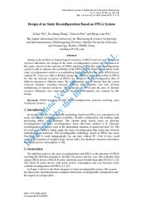
Figure 1: Block Diagram for the MP3 Player
3
Technical Approach
The overall architecture of the media player is comprised of several key hardware components, joined together by a simple, RISC microprocessor. An operating system running on top of the processor provides support for file management and user IO. In this section, I will describe the major modules of the system, explaining the functionality and interfaces of each. Before we begin to discuss each module in detail, I present a high-level overview of the hardware system. The device consists of 2 logical units connected together by the microprocessor and its operating system. The User IO Unit, responsible for user input and visual output, contains a vga monitor and its corresponding video controller, as well as an array of buttons, switches, and LEDs. The buttons and switches pass their state to the processor’s on-chip memory, where these inputs becomes available for computation. The processor sends visual data to the video and LED controllers. The Data IO Unit, responsible for disk input and audio output, contains a compact flash reader, an audio codec, a speaker, and controller logic for these devices. The processor provides addresses, audio sample data, and commands for the compact flash and audio devices by writing to designated portions of its memory address space, and the compact flash controller uses this memory-mapping to send the processor disk data and status updates. As the audio controller receives data from the processor, it internally buffers the data to allow for continuous playback. See Figure 1 for the corresponding block diagram. The target FPGA is Xilinx’s Virtex2p-xup.
3
Compact Flash Controller: This unit reads a sector of data from a compact flash (CF) device and stores it to an internal buffer, where it can be accessed by the main device controller. This module takes advantage of the virtex2p’s on-board System ACE controller; a mechanism internal to the FPGA that transfers information to and from the CF control registers. Essentially, the System ACE provides an interface for communication with the CF device, eliminating the need to deal directly with its pins. (This is necessary, since the FPGA does not expose these pins directly to the user.) Thus, IO from disk is a multi-step process, requiring proper communication with the System ACE controller to initiate appropriate operations on the CF control registers. To successfully read and write the System ACE control registers, detailed timing constraints must be followed. To accomplish this, I designed an interface that consists of 2 small finite state machines (FSM), one to control reading and the other to control writing. These FSMs run on a 32 MHz clock that is synchronized with the CF device. This interface uses a 7-bit address line to specify which ACE control register should be accessed, a 16-bit bi-directional data bus, and a ”commit” bit that allows the FSM to transition past its initial state, performing the requested operation. The output of an ACE read is stored in a separate register, so that it can be referenced after the read initially occurs. In addition to communicating with the System ACE interface, the compact flash controller abstracts the process of reading CF sector data. Reading data from a CF device is a fairly intricate process that involves a large number of reads and writes to the CF control registers– or in our case, the System Ace interface. To briefly summarize the steps involved, one begins by specifying the logical address of the desired sector. Then, the compact flash controller must acquire a lock on the CF device, issue the desired command to the device (in this case a read), and wait for the data buffers to become full. Data is read into 32 byte buffers until all data (512 bytes/sector) has been read. Finally, the CF lock must be released, so that new CF operations can take place. For a precise description of this process, see the SystemACE Compact Flash Solution reference. To implement the specification, I created several registers that communicate with the processor through memory mapping. 4 registers are used to construct the logical block address for the read (LBA0 - LBA3) and an internal 512 byte RAM holds the CF data. To access this data from the processor, an auto-incrementing offset register (CF-OFFSET) controls which 16-bit word of the sector will be output from the data register (CF-DATA). Finally, a control/status register (CF-STATUS) is used to initiate the read command. When a positive value is written to this register, a Direct Memory Access style transfer is initiated. Essentially, the processor writes this register to inform the CF controller that a read should be started, and is then free to go on with other work. The status register is reset to 0 during the read, and it is set to a negative value when the read has finished, informing the processor that the data transfer is complete. Thus, the software interface to read a sector of CF data is simple. One must set the appropriate logical block address, initiate a read by writing a positive value to the control/status register, poll the value of this register until it becomes negative, then read from the CF data register 256 times (if all 512 bytes of data are required). Notice that
4
the offset register need not be used in this scenario, since it automatically increments. If one wishes to access the CF data in a random-access paradigm, then the offset register is set to the appropriate value and a single read from the CF data register is performed. I decided to use polling instead of interrupts for status communication, since the typical amount of data traffic is low. This means that the polling overhead will be negligible, and that both the software and hardware can be simpler. One other interesting design decision that arose during the development of the CF controller was whether the controller should write its data directly to the processor’s memory, bypassing the internal buffer. This would eliminate the CF offset and data registers and make the software to read a sector of data simpler. Ultimately I decided not to implement this idea, since it would require adding an additional port to the memory. Adding ports to a memory increases its size and access latency. It also adds the possibility of a structural hazard on the memory, if both the processor and CF controller are attempting to write to the same location. I decided that these complications weren’t worth the slightly simpler software interface. Audio Codec Controller: This unit performs IO with the FPGA’s built-in AC97 audio codec, by presenting serialized audio data and control signals. The unit can simultaneously capture audio from the board’s microphone input jack and output audio sample data received from the main device controller. All audio data is stored in stereo, uncompressed PCM format, sampled at a rate of 48 KHz with 8-bit samples per channel. This decision was made as an attempt to keep the audio file size as small as possible without requiring complex hardware decoding. Using 8-bit samples causes audio quality to suffer somewhat, but not enough to warrant a serious problem. Since the device uses CF for storage, keeping the file size small outweighs the need for pristine audio quality. Audio data is presented to the AC97 codec in 256-bit frames, which contain both control bits for the audio codec and the sample data itself. To achieve this, the module contains a large finite state machine that takes the two 8-bit input samples, zero-extends them to the appropriate length, and packages them into a properly formatted frame. This frame is then sent one bit at a time to the audio codec, on a 12.288 MHz clock. Notice that one frame is sent at a rate of 12.288 MHz / 256 = 48 KHz, matching the stored audio’s sample rate. This means that samples are delivered to the codec at the appropriate speed. The precise format of these frames can be found in the LM4550 data sheet. The inputs to this module come from three memory-mapped registers–one containing the audio sample data (AC97-DATA), one containing the current volume (AC97-VOLUME), and a control register (AC97-CONTROL) to issue play/pause commands to the audio controller. The data input is formatted as 2 unsigned, 8-bit integers (one for each channel), concatenated together into a 16-bit word with the left sample data occupying the most-significant bits. The volume input is a 5-bit value that represents attenuations from 0 dB to 46.5 dB in 1.5 dB steps. If the control register is set to 0, the controller pauses. This is accomplished by muxing in constant zeros (which represent no sound) for all audio samples and disabling the write enables for both the read and write addresses of the internal audio buffer, which is described next. When this register is set to a non-zero value, the controller passes audio samples through the audio buffer, as in normal operation. 5
In order to prevent major gaps in the audio stream, due to the delay associated with reading a CF sector, this controller maintains an internal buffer that stores unprocessed audio data input. The buffer consists of two 512-byte RAMs with separate, auto-incrementing read and write addresses, as well as a flag that determines which RAM is ”active” (being read). To begin, the active RAM is populated with audio data by the main device controller. Then, when the controller is set to ”play” mode, data from the active RAM is packaged into AC97 frames, as described earlier. New audio data sent to the audio controller from the main device controller is written to the inactive RAM, overwriting any used data. When the buffer’s read address overflows back to zero, the active RAM flag alternates. Audio data is continually read and written in this fashion until the controller is set to ”pause” mode. This buffering is sufficient, since reading a sector of data from CF into the audio buffer takes, on average, 6000 cycles. Running on a 32 MHz clock, this takes about 0.2 ms. Reading a sector of data from the audio buffer takes 512 cycles running on a 48 KHz clock, which takes about 10 ms. Since the time necessary to fill the inactive buffer is significantly less than the time necessary to read the active buffer, this scheme prevents gaps in audio playback. Input Unit: This simple component takes advantage of the Digilent DIO4 extension to the FPGA. This extension board provides 5 push buttons, 8 switches, and a variety of LEDs and seven segment displays. This unit captures all such button-presses and switch-flips and stores them in internal registers, for use by the main device controller. I created a simple, memory-mapped controller that allows the inputs and outputs to be configured by software. To do so, 4 registers are used to reflect the current state of all buttons (BTN-IN), switches (SW-IN), and LEDs (LED-OUT and SEV-SEG-OUT). The operating system can then load or store to these registers with the assigned memory addresses, mapping functionality to inputs as it sees fit. The final version of the operating system uses 3 buttons, whose functionalities change depending on the current state of the system. In addition to this primary functionality, the seven-segment displays have proven to be very valuable for monitoring internal states of the system. Using the switches as select lines for a MUX, I am able to easily monitor the important data lines for each module of the system, creating a method to debug hardware problems. Main Device Controller: The main device controller is a simple microprocessor, which runs code to connect all of the individual modules together into a complete system. The microprocessor, which runs at 32 MHz, implements the P37X ISA–a simple RISC ISA used for the undergraduate processor design course. During the development of the Operating System, I debated adding a new ”move” instruction to the ISA, which transfers the content of one register to another, since I used this programming construct quite often. I ultimately decided not to make this addition, in order to keep my operating system compatible with the undergraduate instruction set. This way, students interested in modifying the operating system for future projects can do so with 6
no compatibility issues. The processor communicates with all other modules in the system through memory mapping. This simplifies the operating system and removes the need for special IO instructions or other complicated software procedures to drive the hardware. Indeed, the other modules in the system have been purposefully designed to allow the processor to be as simple as possible. Specifically, the processor is totally ignorant of disk, audio, video, and user IO, believing that all of these are just normal memory addresses. Video Controller: This component performs IO with a standard monitor, by reading values from a dedicated video memory. The video controller provides the OS with the facility to give the user visual feedback of the system’s state. A separate video memory is used to store display data, which is then sent to a VGA controller and, ultimately, to a monitor. The input data to this memory typically comes from bitmap files stored on disk. The video controller uses 16-bit addresses and data values, divided as follows: Bit[15] Bits[14:10] Bits[9:5] Bits[4:0]
Reserved Red Green Blue
This system supports a total of 32,768 colors and 15,872 pixels (a 128 pixel x 124 pixel square), which allows for a display that holds 11 rows of text, each containing roughly 25 characters. The graphics are of very low resolution, so images look pixelated when viewed on a large monitor. If this prototype were ever to become a real system, a much smaller display with smaller pixels would be used, making the image look crisper. Operating System: While the microprocessor provides the physical connections between each module of the system, it must be programmed to actually use these links. The Operating System is the facet of my original design that has changed the most since my original design proposal. Specifically, it has been greatly enhanced to support new types of media, pass control to other applications, and improve system usability. The OS has several major functions–managing files stored on disk, mapping characters to the display, displaying graphics, passing control of execution to other programs, and assigning user actions into appropriate system events. File management is accomplished by pairing the FAT16 filesystem present on the CF device with a very simple file list. The file list contains a mapping of file names to starting sectors, lengths, and file-types. When the operating system first runs, it traverses through the root directory of the CF’s FAT16 filesystem, examining the extensions of all file entries. For each entry that is valid, not deleted, and of a proper extension (.obj, .bmp, .wav, and .txt in the current implementation), the OS extracts the file’s starting cluster and length. The cluster 7
number is then converted into a disk sector number, and this value, along with length and an identifier of the file’s type, is copied to the file list. In this procedure, the root directory of the FAT16 filesystem native to the CF device is converted into a much simpler file list, which contains only the information needed to locate the file on disk. The main reason for creating this pseudo-filesystem instead of continuing to use the CF’s FAT filesystem directly is the limited memory available to the processor. Since the P37X ISA is only 16-bit, this severely limits the amount of data that can be stored in memory. The amount of instructions needed to traverse the FAT, maintain a working directory, and read data in cluster order would require a great deal of memory. (Indeed the code to create the pseudo-filesystem, which requires only a subset of these demands, is quite large.) Since these subroutines would inflate the memory footprint of the operating system, less memory would be available to user applications and data. Thus, this simple, optimized file list relieves some of the system’s memory pressure, while maintaining most of the flexibility and ease-of-use of the FAT16 filesystem. Of course, this simplicity places some restrictions on file management. Primarily, all files must reside in the CF device’s root directory. This prevents user management of files into separate folders. However, since this system uses compact flash instead of traditional disk technology, the relatively small amount of available storage makes this issue less of a concern. In addition, this pseudo-filesystem currently cannot handle file fragmentation. A simple modification in future software revisions could address this issue, however. This modification would entail adding an OS routine to traverse the FAT entries for a given file, and replacing each file’s single starting sector in the file list with an array of starting sectors, representing where each cluster resides on disk. I did not attempt this modification, because I never had files that were large enough to become fragmented. The character mapper is implemented as a simple lookup table that takes as input an 8-bit ASCII character, and outputs a matrix of pixels to be drawn to the screen. Each matrix is 9 pixels in length, with a variable width between 1 and 5 columns. Thus, each character can use at most 45 pixels. Each matrix is stored in 3 consecutive 16-bit words, with the 3 bits not occupied by pixel data storing the width of the matrix. Note that the term ”pixel data” here refers to whether the pixel is set or clear. It does not store any color information. The mapper also keeps track of its current row and column positions in the display for formatting purposes. Displaying Graphics is a simple process that reads image data from disk or elsewhere in memory and copies it to the video memory region (addresses xC000 to xFDFF). To display properly, images must use 16-bit color, and cannot exceed the 128 x 124 pixel dimensions of the video controller. Transfer of Control of Execution to other programs is achieved by one of two processes. If the program to execute is a user application designed to run on top of the operating system, the program data is copied from CF to the user code section of memory (beginning at x3000), then control of the machine is passed to the new program following a callee-save convention, just as standard OS subroutines execute. Upon termination, the user application restores the state of the OS and jumps back to the OS address space. 8
If the program to execute is a stand-alone application or operating system, control is transferred with the aid of the boot ROM, which is described later in this document. Essentially, the OS retrieves the new program’s disk address from the file list, sends this address to the compact flash controller, sets a flag that instructs the boot ROM to load a program, and then jumps to the boot ROM’s address space (xFF00). The boot ROM then copies the new program’s object code to memory, overwriting the OS code. When this is complete, the boot ROM transfers control back to the new program’s starting address. Note that this scenario destroys the state of the OS, but this problem is not major. Guest programs can restart the OS by setting a flag that instructs the boot ROM to load the OS, then transferring control to the boot ROM. The boot ROM then initializes the system in the exact same manner as system power-on. Note that, in the event a guest program does not transfer control back to the OS, the same effect can be achieved by pressing the system’s main reset button. This 2-process control flow transfer system was designed mainly to support programs written for the undergraduate Introduction to Computer Architecture class. These programs assume that they are the only code executing on the machine and occupy the same address space as the OS. This system allows such programs to run properly without any modification, which is ideal. At the same time, this system allows programs that are dependent on the OS to still receive the subroutine support they need.
The operating system will proceed as follows when the system powers on: 1. Traverse the FAT16 root directory to populate the file list. 2. Draw menu graphics to the display. 3. Write the list of file names to the display, using the character mapper. 4. Enter an infinite loop waiting for user input. If the ”up” or ”down” buttons are pressed, scroll through files list, altering which file is highlighted on the screen. If the ”play” button is pressed, select the highlighted item, performing the appropriate action (displaying a graphic, using the character mapper to display text, passing control of execution to a new program, or sending audio data from CF to the audio controller) based on the file’s type. I leave a detailed description of these software routines to the source code and commenting. 5. Upon completion of processing the highlighted item, wait for the user to press any button, then transfer control of execution back to the OS, returning to step 4.
9
Boot ROM: The Boot ROM is a 512-byte, single-ported ROM that is pre-imaged with the instructions necessary to load the operating system when the system starts up. These instructions traverse through the compact flash device’s FAT16 partition table and boot sector, locating the sector address of the filesystem’s root directory. Once found, the boot ROM searches the root directory for a file named RAMIMAGE, which contains the object code of the operating system (or any other program that should be executed on startup). If no such file is found, an error is reported and the system halts. Otherwise, the RAMIMAGE file is copied into the main device controller’s memory, and control of execution is transferred to the operating system’s starting address (x200). If a special flag is set, instead of searching for a RAMIMAGE file, the Boot ROM assumes that the proper disk address has already been sent to the compact flash controller, and the file pointed to by this address is copied to the main device controller’s memory. Note that on system startup or reset, this flag is clear, so the OS will always be loaded.
Figure 2 is a table of all memory-mapped devices used in the system, their dedicated memory addresses, and their functionality. These specify the complete microprocessor interface to the media player’s devices. Memory Address xC000 - xFDFF xFE03 xFE04 xFE05 xFE0B xFE0C xFE0D xFE0E xFE0F xFE10 xFE11 xFE12 xFF00 - xFFFF
Device VIDEO MEMORY BTN-IN, SW-IN LED-OUT SEV-SEG-OUT LBA1, LBA0 LBA3, LBA2 CF-OFFSET CF-STATUS CF-DATA AC97-DATA AC97-VOLUME AC97-CONTROL BOOT ROM
Purpose stores pixel data to send to the display stores the state of user controlled buttons and switches stores the current state of the extension board LEDs stores the number to be printed on the seven-segment displays contains bits [15:0] of the CF sector to read contains bits [27:16] of the CF sector to read specifies which 16-bit word of CF sector data is output pos. → begin CF read, neg. → CF read complete outputs a 16-bit word of CF sector data provides left and right channel audio sample data sets the master volume 1 → play audio data, 0 → pause audio data stores the code needed to load the OS from disk
Figure 2: Memory-Mapped Microprocessor Interface to the System
10
4
Technical Challenges and Interests
The principle technical challenge encountered during the implementation of this project dealt with the timing and synchronization of hardware devices. Since several devices run on different clock speeds, ensuring their synchronization was slightly troublesome. Specifically, clocking issues caused a few strange bugs in my hardware implementations that were very difficult to track down. Identifying this class of bugs became a task of hypothesizing potential places for timing errors and systematically testing each potential problem through experimentation. The resolution to these timing issues was achieved through keeping as much of the system running on a common, fast clock as possible. Devices that required slower clocks were then partitioned into small, isolated segments, which were linked to the rest of the system through registers clocked on the fast system clock. Several cycles of delay were introduced when reading these interfacing registers, to allow the device data to stabilize. Another technical challenge that consumed a large portion of development time was the difficulty of debugging hardware modules. This problem was never completely solved, but progress was made by adding some extra debugging signals to the design. These signals could be viewed on the sevensegment display, which when combined with the facility to single-step the microprocessor, allowed for a moderate degree of debugging. This debugging process lacked many nice features of software debugging, including breakpoint support. Reflecting on this process, adding hardware breakpoint support would have made debugging much easier, and this could potentially be a nice future project area. The most severe technical challenge, which at the time this document was written has not been solved, involved the proper formatting and sample-rate of audio samples. While this was not an issue for input received from the board’s built-in microphone, samples passed to the audio controller from a wav file produce a muddy, unappealing noise. The reasons for this phenomenon are currently unclear. Originally, I thought that the problem was caused by an inconsistency between the sampling rate of the AC97 codec (48 KHz) and the wav files (8 KHz). I addressed this problem by re-sampling the input wav files to match the rate of 48 KHz, but the problem persisted. I then experimented with various data formatting combinations, including the endedness of multi-byte samples and using sign-extension vs. zero-extension during sample extraction, thinking that perhaps I was sending the audio data in an improper manner. Again, the results were unsatisfactory. Solving this issue will require further experimentation and research. Finally, the most interesting technical challenge that arose during the development of this project was interfacing my system with commercial filesystems and products. This required significant reverse engineering and research of real systems, which provided an interesting insight into the organization and design of these products.
11
5
Conclusions
Overall, I am extremely pleased with the outcome of this project. What started as a vague idea for a project that would be fun, but ultimately limited in usefulness, has become a prototype for a system which provides a useful service in a very user-friendly way. The ultimate result of this project is a hardware and software platform that provides its user with the ability to view images, read text, play games, and execute other programs assembled into the P37X instruction set. (Note that at the time this document was written, the basic software routines and hardware connections to play audio files are in place, but an issue with proper audio sample formatting and rate prevents this feature from correct functioning). To add new media to the system, the user simply copies the relevant files to the root directory of the compact flash device. Upon booting, the system displays all of the appropriate media to user, where standard menu-style interactions mediated by the input buttons control the flow of execution. Decomposing this high-level system into several of its key components is another useful way to analyze my results. Specifically, this project has resulted in 4 modules that could potentially be quite useful for future work in the undergraduate processor design course or elsewhere. 1. A Memory-Mapped Compact Flash Interface for P37X processors provides a simple way for P37X programs to utilize permanent storage. In addition to this hardware support, a software subroutine is provided that abstracts away the few remaining low-level details of this process. 2. A Boot ROM that utilizes the compact flash module enables a P37X processor to load an operating system or other program into the machine’s instruction memory dynamically at run-time. Before this feature existed, the program to be executed had to be pre-imaged into the processor’s memory, which required a great deal of time during hardware synthesis. In addition, the hardware needed to be re-imaged and re-synthesized each time the program to be run was changed. The Boot ROM removes both of these inefficiencies, resulting in faster hardware synthesis, which needs to be performed less frequently. Finally, the Boot ROM allows the contents of memory to be reset along with the rest of the system when appropriate, since resetting the machine transfers control back to the Boot ROM, which re-images memory. 3. A well documented Operating System provides subroutines for reading files, displaying text, and passing control of the processor to other programs. This program, in essence, abstracts away the hardware details and common software routines of the system, allowing applications to be developed more easily. 4. A Memory-Mapped Audio Interface for P37X processors provides hardware support for buffering serial audio data and assembling it into frames that are properly formatted for an AC97 audio codec. At the time this document was written, this module is still a work in progress, as in some cases it produces noisy, muddled audio. All of the major hardware components are in place and well-documented, however, so I feel confident that this interface can be completed with time. As, in my opinion, this module is the least useful of the four major results for the project, I deliberately changed my design goals during implementation, placing less focus on audio and more emphasis on improving usability of the remainder of the system. 12
The design and development of this system forced me to consider and overcome two primary concerns. First, since the entire project centers on the use of compact flash as permanent storage, no progress could have been made if the hardware compact flash controller failed. This concern was magnified by the difficulty in debugging hardware. To overcome this potential problem, I spent the first two weeks exclusively studying specifications for the compact flash standard and data sheets for the target FPGA. This effort proved to be priceless, as I discovered many intricacies that I had not originally anticipated and mandated subtle changes to my initial design strategy. The second concern was one of usability. I feared that I would be successful in creating a working system, but that it would be too difficult to use to be practical. This was a serious concern until the final quarter of the development period. My original design called for a file system that was completely distinct from the FAT filesystem native to the compact flash card. As a consequence, the initial setup of the system would be quite complex. First, a stand-alone application would be required that utilized a computer to search for valid media on the card, recording its location on disk, size, etc. This program would generate the filesystem file for my device, which would then be copied to the compact flash root directory. At this point, the user would be required to examine the CF card’s FAT filesystem to obtain the location on disk of this filesystem file. Finally, this location would be hard-coded into the processor’s memory before synthesis. As is apparent, this process seems more of a hassle than most would be willing to accept. At that point, I realized that it was more important to fix this glaring usability issue than to add additional features to the design. I modified the goals of my project to trade focus away from audio processing to utilizing the CF’s FAT filesystem directly. To do so, I had to study the details of FAT16 and create additional software routines, but the effort was well-rewarded. In my revised design, the user simply must format the CF card using FAT16 and drag the desired files (including the main operating system object code) to the root directory. This was the first point at which the system seemed ”real”. I mention these two points because they demonstrate how this project was truly one of both implementation and design that evolved over time. I was forced to balance trade-offs in usability, performance, and feature richness into the most sensible design for my target audience, while still meeting the time constraints of the project. I found this to be a very interesting and useful exercise in semi large-scale hardware and software design. I also had to make several iterations through a cycle of design and implementation, as new challenges faced during implementation mandated a change to the design. In retrospect, some of these cycles could have been eliminated by more rigorous initial planning, but many of the issues that arose during implementation could not have been foreseen during the design phase. Since I was very careful to ensure that my design plans were flexible, I was able to handle the evolving nature of this project reasonably well. I will conclude with what I found to be the most rewarding aspect of this project–specifically the opportunity to incorporate all that I’ve learned in the CSE curriculum into a cohesive system. Creating this system involved merging concepts from computer architecture and logic design, lowlevel assembly programming, data structures and algorithm design, development of unit testing procedures, and general engineering issues such as time managment and balancing tradeoffs in performance, usability, and functionality. By integrating all of these skills, I was able to convert an idea into a realistic working system that has the potential to be quite useful as a foundation for future projects.
13
6
References
Hedberg, et all. ”Teaching Digital HW-Design by Implementing a Complete MP3 Decoder” International Conference on Microelectronic Systems Education, 2003
Kiatisevi et all. ”Development of an Audio Player as System-on-a-Chip using an Open Source Platform” IEEE International Symposium on Circuits and Systems, 2005
Xilinx Inc. ”Virtex-II Pro Hardware Reference Manual”, 2005
Xilinx Inc. ”SystemACE Compact Flash Solution”, 2002
CompactFlash Association ”CompactFlash Specification Revision 4.0”, 2006
National Semiconductor ”AC 97 Rev 2.1 Multi-Channel Audio Codec with Stereo Headphone Amplifier, Sample Rate Conversion and National 3D Sound”, 2004
”Digital Audio Player: History” wikipedia
Previous designs for a p37X processor and some devices by Andrew Lagattuta, Joe Devietti, Peter Hornyack, Zheng Yang, Josh Gerson
University of Pennsylvania CIS Department ”P37x ISA”, 2007
14