Sensors & Transducers, Vol. 176, Issue 8, August 2014, pp. 49-57
Sensors & Transducers © 2014 by IFSA Publishing, S. L. http://www.sensorsportal.com
FPGA-based Array CCD Sensor Drive System Design and Implementation 1 1
2
Cai Chengtao, 1 Wei Mingyan, 2 Liang Yanhua
College of Automation, Harbin Engineering University, Harbin, 150001, China College of Electrical and Control Engineering of Automation, Heilongjiang University of Science and Technology, Harbin, 150027, China 1 Tel.: 0451-82588940, fax: 0451-82588940 E-mail:
[email protected]
Received: 21 May 2014 /Accepted: 31 July 2014 /Published: 31 August 2014 Abstract: CCD Sensor is the crucial equipment for environment perception which is widely used in various fields such as surveillance, vision navigation and machine vision. The commercial CCD device has been encapsulated the sensor driver inside which is not opened for secondary development. Even this mode facilitates the usage but it really can’t content the customizable need. For solving this challenging but imperative issue, we designed a novel CCD sensor driver system which implements the efficient and effective image acquisition task in customizing approach. The working principle and driving timing sequence about ICX625AQA the interline CCD image sensor used in our system are discussed in detail. For handling with this data intensive task, a high performance Field Programmable Gate Array (FPGA) controller is used for data allocation and translation, the peripheral circuits including AD9974 and CXD3400 drive interface which process the horizontal signal and vertical signal, respectively. The system execute code is compiled and configured in the Quartues II IDE and is simulated used the SignalTap. Some significant results also are proposed at the end of this paper. Copyright © 2014 IFSA Publishing, S. L. Keywords: Interline transfer, Field programmable gate array (FPGA), Dual-channel output, Charge coupled device (CCD), ICX625AQA.
1. Introduction Charge-coupled device (CCD) was invented initially in 1970s, it has many excellent features, such as high sensitivity, large dynamic range, low noise, low power consumption and fast sampling speed [1]. The CCD sensor is such a device for the movement of electrical charge, usually from within the device to an area where the charge can be manipulated, for example conversion into a digital value, and is widely used in professional, medical, and scientific applications where high-quality image data is required particularly in high-precision measurement,
http://www.sensorsportal.com/HTML/DIGEST/P_2258.htm
space remote sensing, robot vision and other associate fields [2-3]. CCD image sensor converts optical signal into charge signal by an optical sensitive surface, and then according with certain rules to output image based on corresponding pulse timing driver. CCD image sensor has better performances in optical filling rate, the uniformity of the response of pixels and quantum efficiency than CMOS and become a science of choice detector for high frame rate imaging acquisition system increasingly [4], the array CCD image sensors can be implemented in several different architectures. The most common are full-frame, frame-transfer, and
49
Sensors & Transducers, Vol. 176, Issue 8, August 2014, pp. 49-57 interline [5]. Each of these architectures has its different approach to the problem of shuttering. The interline transfer because of its advantages and fast readout speed CCD camera has been used in high frequency [6]. The mainly driving circuit of interline transfer CCD includes biased voltage circuit, the horizontal timing-driven circuit and vertical timingdriven circuit. In such circuits mentioned above, the first encountered issue is how to generate the CCD drive timing. In generally, there are four different methods to deal with this challenging matter: direct digital circuits, microcontroller-driven, EPROMdriven and programmable logic devices method [7-9]. Direct digital circuit can get higherspeed driving frequency but accompany with design complication and debug difficulty, Microcontroller drive owns the advantage of easy programming and flexible adjustment but the frequency of driving circuit is too lower to meet the high-speed requirements, EPROM-driven is simple to structure and debug but the usually occupies larger structural space, programmable logic devices such as field programmable gate array (FPGA) includes many advantages such as the ability to re-program in the field to fix bugs, can be repeated or improved after completing the design and easy to update and maintenance. Thus characteristics make the FPGA gradually dominates the application for CCD sensor driver. The driver circuits implemented based FPGA is higher integration, reliability and performance, lower power consumption, cheaper price cost and shorter development cycle period [10]. In this paper, we focus on how to design a novel CCD sensor driver system which implements the efficient and effective image acquisition task in customizing approach based on FPGA. Firstly, we discuss the parameters and work principles about ICX625AQA, one of the typical CCD sensors. Secondly, we describe the design of hardware driving circuit including horizontal drive, vertical drive and voltage generation circuit as well as illustrate the circuit layout and manufacture board. Thirdly, we introduce the workflow of the software running on the FPGA which including the horizontal and vertical timing modules. The simulation of the timing also is conducted to verify the validity of the software. Fourthly, we integrate the hardware part and software part together to achieve the high fidelity image. Finally, we conclude our work and prospect the further tasks.
2. ICX625AQA Structure and Characteristics ICX625AQA is an interline transfer area array color image sensor produced by SONY Corporation, The total gross number of pixels up to 2536 (H) × 2068 (V), approximately 5.24 Mega, The valid number of pixels are 2456 (H) × 2058 (V), approximately 5.05 Mega effective pixels. Each pixel unit cell size is 3.45 μm (H) × 3.45 μm (V), the
50
effective pixel imaging area is 86.39 square millimeter. ICX625AQA fans out the signal within dual output channels. There are three operating modes can be handled when proper operating the sensor which are full pixel scan output model, in this mode, all pixel signals within the same exposure period are read out simultaneously, making this mode suitable for high resolution image capturing; in the 4/16 line output model, the signals are read out four lines (1st, 5th, 8th and 12th line) for each 16 lines and two pixels of the same color are added in the horizontal register, all effective area signals are output at higher frame rate than the all pixel scan mode; the last operation mode is the center readout scan output mode, this mode realizes high frame rates by sweeping the top and bottom of the picture with high-speed transfer and cutting out the center of the picture. The image output rate of the ICX625AQA can achieve to 15 frames/sec in the allpixel scan mode also output using various addition and elimination method [11]. An electronic shutter with variable charge-storage time which makes it possible to realize full-frame still images without a mechanical shutter. High sensitivity and low dark current are achieved through the adoption of Super HAD CCD technology. This CCD image sensor is driven by one four-phase vertical transfer pulse (V1, V2, V3 and V4), one two-phase horizontal transfer pulse (H1 and H2), another electronic shutter pulse (SUB) and one reset pulse (RG) simultaneously. Those various pulses mentioned above combined with each other constitute CCD image sensor’s drive timing pulse.
3. Driver Circuit Analysis and Design Stable power circuit is essential for ICX625AQA work properly. There are several extinguished power circuits to provide energy for the CCD sensor, such as the positive 15 V bias voltage, the negative 8 V bias voltage. The horizontal transfer pulse and the vertical transfer pulses are shown in Fig. 1. Bias voltage circuits not only provides CCD sensor power but also content the power consume in FPGA main chip system, the horizontal drive circuit and vertical drive circuit provides horizontal driving clock signal and vertical driving clock signal for CCD sensor respectively. Each circuit such as Horizontal drive circuit, AD conversion circuit and the vertical driving circuits works in different clock frequencies but shares the common clock synchronization signal. These circuits work harmoniously to ensure the CCD image sensor can output the small analog signals which stand for the environment light intensity. The small analog signals are prone to be influenced by the electronic noise, one AD conversion circuit which holds high magnification times and SNR is used for correct image acquisition [12]. FPGA processors is used to be the main chip which is responsible for outputting timing and controlling signal for each chip desired, at the same time, it also
Sensors & Transducers, Vol. 176, Issue 8, August 2014, pp. 49-57
RG2
RG1 LH1B
0 .1 u F
B10
B4
RG_A
C4 3
C4 4
RG_B
H2B
H1B
LH1A
F10 F9 D10 D9
0 .1u F
H1_B H2_B H3_B H4_B
D0_B D1_B D2_B D3_B D4_B D5_B D6_B D7_B D8_B D9_B D10_B D11_B D12_B D13_B
H1_A H2_A H3_A H4_A
F4 F3 D4 D3
G7 H7 J7 K7 G8 H8 K8 G9 H9 J9 K10 J10 H10 G10
H1A
K9 K3
H2A
G10
H10
J10
K10
K8
H8
G8
K7
J7
H7
G7
G4
H4
J4
K4
J3
H3
G3
K2
H2
G2
K1
J1
H1
G1 H1 J1 K1 G2 H2 K2 G3 H3 J3 K4 J4 H4 G4 D0_A D1_A D2_A D3_A D4_A D5_A D6_A D7_A D8_A D9_A D10_A D11_A D12_A D13_A
0.1uF 0.1uF
0.1uF
C16 C15
C17
3.0V_AFE_DRVDD
C18 4.7uF
G1
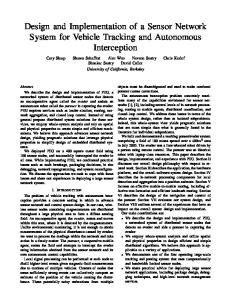
As discussed above, ICX625AQA adopts the dual-channel drive model to fan out the image signals which ask the AD conversion circuit must match this issue. In our system, the high performance AD convert chip named ADA4800 is chosen as a buffer amplifier. In this section, we mainly focus on generating the CCD drive signal, in our work, we select ADI's AD9974 to provide horizontal pulses drive signal, the Circuit diagram of AD9974 is shown in Fig. 2. AD9974 integrates double-pass high-speed signal processing circuit for high speed digital video camera applications. Each channel is
J9
3.1. The Horizontal Drive Circuit
H9
Fig. 1. System hardware block diagram.
G9
specified at pixel rates of up to 65 MHz, and in internal integrated analog front-end processing circuit, including the black level clamping, CDS, programmable amplifier (VGA) and a 14-bit analogto-digital converter circuit. The Precision Timing core in it allows adjustment of high speed clocks with approximately 240 picoseconds resolution at 65 MHz operation. The timing driver provides the high speed CCD clock drivers for the RG1, RG2, H1A to H4A, and H1B to H4B outputs. AD9974 generates flexible high speed timing signals using the Precision Timing core. This core, composed of the Reset Gate RG, Horizontal Driver H1 to Horizontal Driver H4, and SHP/SHD sample clocks, is the foundation for generating the timing for both the CCD and the AFE. A unique architecture makes it routine for the system designer to optimize image quality by providing precise control over the horizontal CCD readout and the AFE correlated double sampling [13]. AD9974 can be seamless connection with ICX625AQA and can conveniently connect the clock signals to the ICX625AQA pins i.e. H1A, H1B, H2A, H2B, and RG1, RG2. AD9974 has two three-wire serial communication interfaces which can be used to configure the internal registers for generating the horizontal clock pulse and forward analog control signal. There also are two high-speed master clock signals named CLI_A and CLI_B are generated as internal reference clock inputs which is should be pay attention in PCB layout to avoid noise interference.
receives the valid data coming from AD conversion output for further processing. The relationship between those circuits mentioned above is shown in Fig. 1.
DRVSS_B J8 DRVSS_A J2
DRVDD_B DRVDD_A
FB FB
AD9974
LDO_OUT_A DVDD_A AVDD_A
RG_VDD_B HVDD_B
HD_B
VD_B
CLI_B
SL_B
D8 C8 B8 A9 E8 E7 SDATA_B
SCK_B
HD_A
VD_A
CLI_A
SL_A
AVSS_B B7 AVSS_A B1
CLI_B CTL_B[0..4]
C3 5
C3 4
CLI_A CTL_A[0..4]
0 .1 u F
C3 3
SDATA_A
SCK_A 0 .1 u F 0.1u F 0 .1 u F
DVSS_B F8 DVSS_A F2
SCK_B SDATA_B SL_B CLI_B VD_B HD_B
SCK_A SDATA_A SL_A CLI_A VD_A HD_A D2 C2 B2 A4 E2 E1
D7
REFB_B
REFT_B C7
D1
REFB_A
REFT_A
CCDINM_B A6
CCDINP_B A7
CCDINM_A A1
CCDINP_A
0 .1 u F C2 2
H5 J5 G5 F5 E5 C5 B5 D5 K6 J6 H6 G6 F6 E6 D6 C6 B6 K5
RGVSS_B C9 RGVSS_A C3 HVSS_B E9 HVSS_A E3
RGVDD_A HVDD_A
A2
C4 E4
U2
0.1uF
C10
C10 E10
C1
0.1uF 0.1uF 0.1uF
0.1uF
C6
C5
0.1uF 0.1uF 0.1uF
C4 C3 C2
C13 C14 4.7uF 4.7uF C12 C11
F1 A3
LDO_OUT_B DVDD_B AVDD_B
FB
L2 0.1uF
C1
A10
A5
FB
L1
F7 A8
GND GND GND GND GND GND GND GND GND GND GND GND GND GND GND GND GND GND
IOVDD_B IOVDD_A
0 .1 u F
3.6V_HVDD3.6V_HVDD
B9 B3
C3 6
L3 L4
C3 0
Fig. 2. AD9974 Signal connection schematics.
51
Sensors & Transducers, Vol. 176, Issue 8, August 2014, pp. 49-57
Header 14
VOUT1
GND
VDD_15V
RG1
LH1A
H1A
H2A
H1B
H2B
VSUB V3B
V3A
V3D
V1A V1B V2 V3A V3B V4
14 16 12 17 19 13
20
XSHT XV1 XSG1A XSG1B XV2 XV3 XSG3A XSG3B XV4 XSG3B
XSG3A
XSG3D
XV3
VDD
2 6 8 7 10 3 5 4 9
1
GND
XSG3C
0.1uF 0.1uF
V3C
C42 C41
SHT VH
CXD3400N
15
U5
0.1uF
C39
VDD_15V
3.3V_FPGA_IO
VL
XV1
XSG2B
XSG2A
XV4
XSG2D
18
Fig. 3. CXD3400 Signal connection schematics.
52
LH1B
RG2
1 2 3 4 5 6 7 8 9 10 11 12 13 14 VDD_15V
VOUT2
GND
GND
SUB
VDD_-8V
V1
V2A
V2B
V2C
0.1uF
V1
V2B
V2A
C31
100K V4
V2D
V2C
XSHT XV1 XSG1A XSG1B XV2 XV3 XSG3A XSG3B XV4 XSG2C
XV2
XSUB
VDD
G N D 11
2 6 8 7 10 3 5 4 9
U1 0.1uF
C7
14 16 12 17 19 13
SHT VH
VDD_- 8V
CXD3400N
15
1M R7
V1A V1B V2 V3A V3B V4
20
C9
0.1uF 0.1uF
C8
3.3V_FPGA_IO
VL
1
V2D
V3A
V3B
V3C
V3D
VDD_15V R2
MA111
0.1uF
D1
2200pF C3 2
18
D2
0 .3 3 u F C1 9
MA111
C24
C29 20v 3.3uF
C27 20v 3.3uF
V4
C23
C2 1
0.1u F
0.1uF
P3
1 2 3 4 5 6 7 8 9 10 11 12 13 14
C20 20v 3.3uF
The power stability is crucial for ICX625AQA, even minimums voltage fluctuation can lead to this
P4
3.3. Voltage Generation Circuit
GND
In generally, The output voltage amplitude comes from FPGA can’t satisfy the requirement of CCD sensor vertical drive signal, To deal with this issue, we choose the exclusive drive chip produced by SONY named CXD3400 as CCD vertical driver chip. CXD3400 contains six channels and can work at the high-speed readout mode. The CCD sensor ICX625AQA must be driven in ten channel vertical signals which are Vφ1, Vφ2, Vφ3 and Vφ4 four-phase vertical drive signal while the signal Vφ2 and Vφ3 further are divided into four signals. So, we have to use two CXD3400 chips to deal with the ten signals simultaneously. When the conversion inside the CCD sensor has been completed, the signals of Vφ2 and Vφ3 provide the VH, VM and VL three-level signals synchronically to read out to the vertical conversion signal. The one thing we have to emphases is that the pins of CXD3400 process circuit must be connected to FPGA pins directly in specific rule in order to ensure proper signal generation. The vertical drive circuit schematics based on two CXD3400 is shown in Fig. 3.
Header 14
high-precision sensors break down. On the other hand, the power has to own some redundancy capacity than pre-estimated total power consume [14-15], in our paper, we adopt the special power supply chip produced by Texas Instruments named TPS54594 which is a DC/DC power switching chip with dual 5 V (4 A/2 A) output and requires 12 V input. The 5 V/4 A power channel supply power to the TPS54286 and two LDO which are other power switching chips, The TPS54286 outputs the 3.3 V voltage for FPGA system while the two LDO output 3.0 V and 3.6 V voltage for AD9974 respectively. The 5 V/2 A power channel supply power to LT3486 exclusively. The LT3487 dual channel switching regulator generates positive and negative outputs for biasing CCD imagers. The device delivers up to – 8 V at 90 mA and 15 V at 45 mA from a lithiumion cell, providing bias for many popular CCD imagers. Low cost LDO linear regulator, low noise, quiescent current, which is its outstanding advantages. DC/DC switching power supply chip advantage is the high conversion efficiency can be high current, but the output disturbance is large, the volume is relatively large. According to the advantages and disadvantages of the two power chip, we chose this construct power circuit. Voltage Generation Circuit schematic diagram is shown in Fig. 4.
3.2. The Vertical Drive Circuit
Sensors & Transducers, Vol. 176, Issue 8, August 2014, pp. 49-57 VDD_5V_4A
C45 16v 10uF
C46 16v 10uF
VDD_5V_4A
3.6V_HVDD
GND
D3 MBRA340
P A D 15
C55 470pF R11 10R 1%
GND
C56 470pF 16v 4.7uF
TPS54286PWP
GND
GND
GND
R13
R15
GND
GND
D4 MBRA340
R12 10R 1%
C49 6v 4.7uF
LP2985-N C54 X7R 1uF
GND C58 X7R 0.01uF
GND
GND
R16
R14
1% 8.06K
1% 24.9K
VDD_5V_4A
3.0V_AFE_DRVDD R33
U9
10K
VDD_5V_4A
P ow e rP17a d
VIN2 VBST2 SW2 PGND2 EN2 PG2 VFB2 VREG5
GND U2_EN
VDD_5V_2A_FB
C71
10uF
22uF
620
300
300
VIN_12V 1 3 2
VIN_12V R17 22.1K U2_EN
D6 LED2
蓝
D7 LED2
C64 10uF
C62 22uF
GND
C79 0.1uF
D9 LED2
GND
6 5 7 8
27pF R26 324K 1%
VDD_-8V
GND
红
D8 LED2
C65 X7R 0.01uF
U11 C77
C61 22uF
C63 10uF
10v C80 10uF
VDD_IO C81 100nF
LT3487
Vin DN FBN RUN/SS G N D 11
R18 22.1K 绿
L11 15uH SWP
620
C74 1uF
GND J1
C59 6v 10uF
GND
2
R30
15uH
SWN
R29
L10
15uH
V ba t
R28
L9
3
VDD_SOM
R27
黄
25v C72 2.2uF
4
VDD_5V_2A 3.3V_FPGA_IO
R23 22.1K
C60 X7R 1uF
VDD_5V_2A
GND
VDD_5V_4A
D5 LED2
C70
ON/OFF LP2985-N
GND
GND
红
3 0R R20 124K R22 VDD_5V_2A_FB
L8
C73 1uF
GND
2K
4.7uH C66 0.1uF
TPS54494
R24 22.1K
R31
16 15 14 13 12 11 10 9
BY P A4 S S
C69 10uF
VDD_5V_2A
VIN1 VBST1 SW1 PGND1 EN1 PG1 VFB1 GND
V out
C68 R21 124K 22uF VDD_5V_4A_FB
0R
1 2 3 GND 4 U2_EN 5 6 VDD_5V_4A_FB 7 8
G N D2
L7
R19
U10
0.1uF
C67
V in
4.7uH
VIN_12V
ON/OFF
5
1% 8.06K
VIN_12V
GND
C51 16v 10uF
C53 16V 47uF
1
1% 24.9K
3
L6
C57
10K
VDD_SOM
18uH 2A
C47 47nF
BY P A4 S S
C52 16V 47uF
14 13 12 11 10 9 8
PVDD2 BOOT2 SW2 BP SEQ ILIM2 FB2
V out
L5
C50 16v 10uF
PVDD1 BOOT1 SW1 GND EN1 EN2 FB1
G N D2
1 2 3 4 5 6 7
C48 47nf
V in
U8
18uH 2A
U7
5
GND 3.3V_FPGA_IO
1
R32
CAP FBP Vpos
1 9
C76 10pF
C75 16v 0.1uF
1% R25 549K 16v C78 10uF
10
VDD_15V
GND
GND
GND
Fig. 4. Voltage circuit schematics.
3.3. Circuit Layout and PCB Board Manufacture Base on the circuit schematics design mentioned above, we laid out the printed circuit board (PCB) in the DXP2004 the integrated development environment (IDE). The manufacture of the PCB board is shown in Fig. 5. The No. 1 stands for the combination of the CCD and lens with a pins connector to facilitate change and protect the CCD sensor [16]. The No. 2 and No. 3 stand for the combination of the horizontal drive chip AD9974 and vertical drive chip CXD3400 respectively as well as the peripheral configuration circuit. The Horizontal and vertical drive chips are layout around the CCD sensor adjacently for eliminating noise interference [17]. The component labeled No. 4 is the power supply circuit. The No. 5 states the output interfaces, including network interface and VGA interface. The No. 6 indicates core board interface. Through conducting whole experiment, this board is working properly and generating the necessary timing signals for the CCD image sensor.
L1, L2, a clock signal, the reset switch signal is RG1, and RG2, the vertical transfer clock signal is V1 to V4, the substrate clock signal is SUB. For clearing the residual charge in the sensor, the RG pulse signal is used to reset the output unit. SUB electronic shutter signal for generating a high pulse which is used to clear the accumulated charge before the next exposure of the CCD [18]. At the same time, the AD9974 generates the horizontal drive signal which decomposed into SHD, SHP, HBLK, PBLK, CLPOB and DOUTCLOCK signals. SHP and SHD signals are correlated but have a certain phase difference. CXD3400 provides the vertical transfer clock signal which is input to the CCD sensor directly. All signals have fixed phrase separation and all are controlled by the FPGA, so the drive timing design we are going to discuss is crucial to get high quality image.
4. Drive Timing Analysis and Design 4.1. Driver Timing Analysis ICX625AQA has three operating modes. We use the all-pixel scan output mode to get the higher resolution image. In this mode, the main driving clock signal for the horizontal transfer is H1 and H2 while the last stage of the horizontal transfer use the
Fig. 5. Soldering template.
53
Sensors & Transducers, Vol. 176, Issue 8, August 2014, pp. 49-57
4.2. Driver Timing Design In our program, we design the complicated driver timing in Verilog HDL language [19]. The detailed procedure about the software diagram is shown in the Fig. 6. The program running in FPGA is divided into several modules. The pixel counter module which initialize the AD9974 controls the horizontal and vertical signal by means of two counters [20], AD9974 initialization module is called three-wire serial interface module to do the initialization of AD9974 module. The counters begin to count as soon as the configuration procedure finished. So the AD9974 module and the CXD3400 module generate horizontal and vertical clock signal synchronically. When one frame AD conversion is completed, the counter module calls the image read module reads image data. We will discuss the horizontal and vertical drive timing design separately in following sections.
synchronical valid period, the HBLK and PBLK signals occupy 615 bits during in effective voltage phrase, in the similar way, CLPOB signal occupies 40 bits, the rest are blank bits.
Fig. 7. The basic horizontal signal timing diagram.
4.4. Vertical Drive Timing Design Once anyone image frame is outputted, the next frame must be transferred to vertical field. As we know the CXD3400 chip provides the vertical transfer clock signal which is valid during this transferring period. When each row of pixels shifts, CXD3400 module acts once. The four-phase vertical transfer signals are shown in Fig. 8. The signals also are combined by CXD3400 to meet the requirement of vertical transfer clock.
Fig. 6. The workflow of software.
4.3. Horizontal Drive Timing Design Horizontal drive module consists of three submodules which are three-wire serial write module, AD9974 register initialization module and vertical sync counter module [21]. Through the initial configuration, the AD9974 internal Precision Timing core uses a master clock input (CLI_X) as a reference. This clock input should be the same as the CCD pixel clock frequency. The internal timing core divides the master clock period into 64 steps or edge positions, the high speed clocks, RG, H1 to H4, SHP and SHD, are generated by positions. The RG pulse has programmable rising and falling edges and can be inverted using the polarity control. The H1 and H2 horizontal clocks have separate programmable rising and falling edges, as well as separate polarity control. The time sequence of those signals is shown in Fig. 7. There are 1924 raw bits signal transferred by horizontal synchronization signal HD. There are 1228 effective pixels within the raw bits. In
54
Fig. 8. All pixels read timing diagram.
4.5. Timing Logic Simulation The designed and implemented drive timing program is simulated in the Signal Tap IDE [22]. The simulation of three-wire serial control signal which is used in AD9974 is shown in Fig. 9. The simulation signal contains enable signal Send_En, complete signal Send_Done, allowing signals SL and transmit serial clock signal SCK. When Send_En become effective status, SL signal becomes low to activate
Sensors & Transducers, Vol. 176, Issue 8, August 2014, pp. 49-57 serial port to sent out valid data at the edge moment of SCK rising, When the data transfer finished is completed, Send_Done will drop down the voltage level to notify FPGA that the whole frame data has been transferred completely, then the FPGA will start
up or terminate the next frame data acquisition process according to the situation of Send_En signal. SL signal is effective at each rising edge of SCK data read period. SL at least keeps ahead the rising edge of SCK tls nanoseconds.
Fig. 9. Serial control module simulation diagram.
FPGA must provide the vertical sync and horizontal sync clock signal to motivate the AD9974 generates the horizontal drive clock [23]. Meanwhile, the Sub exposure signal and the vertical transfer clock signal also are accompanied by FPGA. The signal time sequence is shown in Fig. 10. In this figure, we can figure out that when the horizontal synchronization signal is valid, the signals of Xsub and Vsub combines to generate Sub signal as well as the signals V1-V4 combines to generate the vertical transfer signal.
Fig. 11. The waveform of vertical drive signals
Fig. 10. Sync signal and the vertical transfer signal simulation diagram.
5. Experimental Test After the completion of the production of circuit boards, through the timing analysis, we completed the design of the driver modules, and ultimately successful run on the board in the simulation test. AD9974 and CXD3400N output signals are shown in Fig. 11. Because the oscilloscope only has two probes, SUB signal is a reference signal for the combination of V1-V4 in Fig. 11. Fig. 12 is the waveform of the horizontal drive signal, the vertical works in the idle phase. The bandwidth of oscilloscope is 100 MHz, and when the horizontal drive signal reaches 60 MHz, the waveform is display with a certain amplitude error.
Fig. 12. The waveform of horizontal signals.
6. Conclusions In this paper, we discussed how to design and implement the novel CCD sensor driver system
55
Sensors & Transducers, Vol. 176, Issue 8, August 2014, pp. 49-57 based on FPGA. The working principle and driving timing sequence about ICX625AQA the interline CCD image sensor used in our system are discussed in detail. We adopted the special vertical driver chip CXD3400 and horizontal driver chip AD9974 to enhance anti-jamming capability of the circuits, the peripheral circuits including AD9974 and CXD3400 are illustrated as well as some simulations are conducted to verify the correctness of the process program. Our work provides a practical approach to implement the efficient and effective CCD sensor image acquisition task in customizing pattern.
Acknowledgements The authors would like to thank to the reviewers for their valuable comments which have improved this paper significantly. This work is supported by National Natural Science Foundation of China (No. 61203255), Fundamental Research Funds for the Central Universities (HEUCFX41304), the Science Foundation for Youths of HRB (No. 2013RFQXJ106) and the Heilongjiang Province Postdoctoral Sustentation Fund (No. LBH-Q11135).
References [1]. He G., Wang X., Li D., et al., A high-speed image sensing technique with adjustable frame rate based on an ordinary CCD, Optik-International Journal for Light and Electron Optics, 119, 11, 2008, pp. 548-552. [2]. Leach R. W., Design of a CCD controller optimized for mosaics, Publications of the Astronomical Society of the Pacific, 1988, pp. 1287-1295. [3]. Xu Z., Wei J., Zhou Q., et al., Design of the driving system for visible near-infrared spatial programmable push-broom remote CCD sensor, Proc. SPIE, Advanced Sensor Systems and Applications IV, 7853, 2010, 78531O. [4]. Xianjun Wang, Circuit Design for High Integrated Photoelectric Encoder Base on SOC Singlechip, Based Optics and Precision Engineering, 19, 5, 2011, pp. 1082-1087. [5]. Zhou Q., Ning T. G., Pei L., et al., CCD fiber Bragg grating sensor demodulation system based on FPGA, Proc. SPIE, Advanced Sensor Systems and Applications IV, 7853, 2010, 785305-785305-5. [6]. Rafael C. Gonzalez, Richard E. Woods, Digital Image Processing, Pearson Education, Inc., 2010, pp. 347-355. [7]. Xianjun Wang, Circuit Design for High Integrated Photoelectric Encoder Base on SOC Singlechip, Based Optics and Precision Engineering, 19, 5, 2011, pp. 1082-1087. [8]. Li B., Song Q., He C., et al., Circuit design of an EMCCD camera, Proc. SPIE, 8453, 2012, 84532O. [9]. Kotov I. V., Frank J., Kotov A. I., et al., CCD characterization and measurements automation, Nuclear Instruments and Methods in Physics Research Section A: Accelerators, Spectrometers, Detectors and Associated Equipment, 695, 2012, pp. 188-192.
56
[10]. Rui Tian, Chunyu Chen, Design of the Drive Circuit of the Large Array Frame Transfer CCD Based on FPGA, in Proceedings of the Industry Conference, 2, 2010. [11]. Sony Corporation, Diagonal 11.016 (Type 2/3) progressive Scan CCD image Sensor with Square Pixel for Color Cameras, Sony Corporation, Japan, 2007. [12]. Cheng Y., Li T., The research and analysis of TDICCD dynamic driving design, in Proceedings of the 5th International Symposium on Advanced Optical Manufacturing and Testing Technologies. International Society for Optics and Photonics, 2010, 76580U-76580U-6. [13]. Analog Devices corporation, Dual-Channel, 14-Bit, CCD Signal Processor with Precision Timing Core, Analog Devices Corporation, 2009. [14]. Wei Zhou, Jianying He, Jugen Nie, Implementation of the Programming and Configuring of CPLD and FPGA, Computer and Digital Engineering, 34, 1, 2006, pp. 100-102. [15]. Si G., Li Y., Guo Y., Timing generator of scientific grade CCD camera and its implementation based on FPGA technology, in Proceedings of the 5th International Symposium on Advanced Optical Manufacturing and Testing Technologies. International Society for Optics and Photonics, 2010, pp. 76585Y-76585Y-7. [16]. Zhenglei Sun, Xiaodong Wang, Hongfeng Qu, Design for driving control of high frame rate area array CCD based on FPGA, Application of Electronic Technique, 38, 7, 2012, pp. 65-66. [17]. Xu T., Xiong X., Li M., Design of FPGA based on linear array CCD driver circuit, in Proceedings of the IEEE 9th International Conference on Electronic Measurement & Instruments (ICEMI'09), 2009, pp. 2-766-2-769. [18]. Wang H., Yan S., Zhou Z., et al., Fieldprogrammable gate array-based hardware architecture for high-speed camera with KAI-0340 CCD image sensor, in Proceedings of the 5th International Symposium on Photoelectronic Detection and Imaging. International Society for Optics and Photonics (ISPDI’2013), 2013, pp. 890811-890811-8. [19]. Jun Ma, Shaoyi Li, Li Sun, Analysis of the Interaction Between CCD Driving Circuit Design and Image Quality, Measurement and Control Technology, 30, 3, 2011, pp. 5-7. [20]. Ma Q. J., Song K. F., Qu Y., et al., Design of CCD circuit systems for ultraviolet limb imaging spectrometers, Guangxue Jingmi Gongcheng (Optics and Precision Engineering), 19, 7, 2011, pp. 1538-1545. [21]. Zhong W., Tian B., Gao Y., et al., The research of linear array CCD dynamic image acquisition and processing, in Proceedings of the IEEE International Conference on Measurement, Information and Control (ICMIC), 2, 2013, pp. 964-967. [22]. Ningning Li, Zhinong Li, Zhihua Liu, The Design of a Linear CCD Driving Circuit Based on CPLD, Mechanical Design and Manufacturing, 6, 2011, pp. 30-32. [23]. Kai Yang, Zhenshen Li, Suying Lv, Design of Driving Circuit of Area Array CCD with Interline Transfer Based on FPGA, Shanghai Electric Institute, 15, 1, 2012, pp. 38-43.
Sensors & Transducers, Vol. 176, Issue 8, August 2014, pp. 49-57
___________________ 2014 Copyright ©, International Frequency Sensor Association (IFSA) Publishing, S. L. All rights reserved. (http://www.sensorsportal.com)
57