Dall Energy Biomass Furnace Verification Protocol Low particle, CO and NOx emission furnace
April 2011 Project Manager:
Marianne Kyed Ørbæk
Dall Energy Verification Protocol
1. TABLE OF CONTENTS 1. TABLE OF CONTENTS ........................................................................................2 2. INTRODUCTION ...................................................................................................4 2.1. 2.2. 2.3. 2.4. 2.5. 2.6.
NAME OF PRODUCT ..............................................................................................4 NAME AND CONTACT OF VENDOR ..........................................................................4 NAME OF CENTRE/VERIFICATION RESPONSIBLE......................................................4 VERIFICATION AND TEST ORGANIZATION ................................................................4 TECHNICAL EXPERTS ............................................................................................6 VERIFICATION PROCESS .......................................................................................6
3. DESCRIPTION OF THE TECHNOLOGY .............................................................6 4. DESCRIPTION OF THE PRODUCT .....................................................................7 5. APPLICATION AND PERFORMANCE PARAMETER DEFINITIONS .................9 5.1. 5.2. 5.3. 5.4. 5.5.
MATRIX ................................................................................................................9 TARGET ...............................................................................................................9 EFFECTS ..............................................................................................................9 PERFORMANCE PARAMETERS FOR VERIFICATION ...................................................9 ADDITIONAL PARAMETERS ....................................................................................9
6. EXISTING DATA .................................................................................................10 6.1. SUMMARY OF EXISTING DATA ..............................................................................10 6.2. QUALITY OF EXISTING DATA ................................................................................10 6.3. ACCEPTED EXISTING DATA ..................................................................................10 7. TEST PLAN REQUIREMENTS ...........................................................................10 7.1. 7.2. 7.3. 7.4. 7.5.
TEST DESIGN......................................................................................................10 REFERENCE ANALYSIS ........................................................................................11 DATA MANAGEMENT ...........................................................................................11 QUALITY ASSURANCE .........................................................................................11 TEST REPORT.....................................................................................................11
8. EVALUATION .....................................................................................................11 8.1. 8.2. 8.3. 8.4.
CALCULATION OF PERFORMANCE PARAMETERS ...................................................12 EVALUATION OF TEST DATA QUALITY ...................................................................12 USER MANUAL ....................................................................................................12 OCCUPATIONAL HEALTH AND ENVIRONMENT ........................................................12
9. VERIFICATION SCHEDULE ..............................................................................13 10. QUALITY ASSURANCE .....................................................................................13
2
Dall Energy Verification Protocol
1. APPLICATION .........................................................................................................16 1.1. MATRIX ............................................................................................................................ 16 1.2. TARGET ............................................................................................................................ 16 1.3. EFFECTS ............................................................................................................................ 16
APPENDICES Appendix 1 Appendix 2 Appendix 3
Terms and definitions used in the verification protocol References Application and performance parameter definitions
3
Dall Energy Verification Protocol
2.
INTRODUCTION Environmental technology verification (ETV) is an independent (third party) assessment of the performance of a technology or a product for a specified application, under defined conditions and quality assurance.
2.1.
Name of product The Dall Energy Biomass Furnace is a low emission and high efficiency biomass furnace, without any moving parts. The combustions principle is gasification in the bottom of the furnace and gas combustion in the upper part. This gives a very low emission of particles, CO and NOx, which stays low during load changes, and even when operated as low as 10 - 20 % load.
2.2.
Name and contact of vendor Dall Energy Venlighedsvej 2 2970 Hørsholm Denmark Phone: +45 29 87 22 22 Contact: Jens Dall Bentzen E-mail:
[email protected]
2.3.
Name of centre/verification responsible FORCE Technology, verification body at the Danish Centre for Verification of Climate and Environmental Technologies (DANETV). FORCE Technology DANETV Air emission and Energy Centre: Verification Test Centre (DANETV) FORCE Technology Park Allé 345 DK - 2605 Brøndby Denmark.
2.4.
Verification responsible Ole Schleicher E-mail
[email protected] Phone +45 4326 7540 Cell phone +45 2269 7540
Verification and test organization The verification was conducted by the Danish Centre for Verification of Climate and Environmental Technologies, DANETV, which performs independent tests of technologies and products for the reduction of climate changes and pollution. The verification will be conducted by the Danish Test Centre DANETV. The verification is planned and conducted to satisfy the requirements of the ETV scheme currently being established by the European Union (EU ETV).
4
Dall Energy Verification Protocol
Verification and tests will be performed by FORCE Technology as Verification body at DANETV Test Centre. The day to day operations of the verification and tests will be coordinated and supervised by FORCE Technology, with participation of the vendor, Dall Energy. The testing will be conducted at the 8 MW Dall Energy Furnace, which is under construction at Andelsselskabet Bogense Fjernvarme, Fynsvej 5, 5400 Bogense, Denmark. The furnace will be operated by the local operators, supervised by Dall Energy, which also will provide the necessary documentation and operation instructions for the tests. Dall Energy will also assist FORCE Technology in the development of the protocol and test plans. An expert group is established to support FORCE Technology in planning, conducting and reporting the verification and tests, and to review plans and reports. The organization chart in Figure 1 identifies the relationships of the organization associated with this verification and tests. Figure 1 Organization of the verification and tests
5
Dall Energy Verification Protocol
2.5.
Technical experts The expert group assigned to this test and responsible for review of test plan and test report includes: Arne Oxbøl (AOX) FORCE Technology Phone: +45 4326 7130 E-mail:
[email protected]
2.6.
Verification process Verification and tests will be conducted in two separate steps, as required by the EU ETV. The steps in the verification are shown in Figure 2. Figure 2 Verification steps
References for the verification process are the Quality Management Plan for DANETV /1/. A verification statement will be issued after completion of the verification.
3.
DESCRIPTION OF THE TECHNOLOGY The Dall Energy furnace is a newly invented combustion design, which in one special designed unit combines the well known updraft gasification technology with a gas combustion section above the gasifier. The unit has no hot moving part inside the furnace. The technology can only work as an integrated part of a biomass combustion plant, consisting of a fuel feeding system, a system to utilize heat and a chimney. To achieve the highest energy efficiency the heat utilizing system includes a wet condensation system. Several other units, e.g. blowers, instrumentation and a
6
Dall Energy Verification Protocol
process control system are necessary to operate the plant. Only the furnace is included in the ETV verification test, as all the surrounding equipment can be selected among different technologies and suppliers. The furnace can be delivered in sizes ranging from 1 MW to 20 MW. The furnace to be verified is 8 MW.
4.
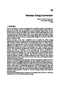
DESCRIPTION OF THE PRODUCT The product is a multipurpose biomass furnace, without any hot moving parts which combines the well known updraft gasification process with a gas combustion section above the gasifier. The following Figure 3 shows the Dall Energy furnace principle diagram.
Figure 3 Dall Energy furnace - Principle diagram
7
Dall Energy Verification Protocol
In the bottom part, the solid fuel is converted into a burnable gas and fine ash. In the top layer, the fuel is dried and pyrolysed. The heat for the drying and pyrolysis process is a combination of convective heat from the gasification gases below and radiation heat from the gas combustion part above. The gas velocity in the bottom part is very low. Consequently, ash particles remain here and the dust emission of the furnace is very low. Due to the very efficient gas combustion the CO emission is very low. Moreover the emission of the fuel NOx is relatively low due to the gasification process. Gas from the bottom part is combusted in the upper section. The gas combustion can operate at low oxygen concentration and maintain very stable flow, temperatures, emissions etc. In combination with a flue gas condensation system and a fuel or combustion air moisturizing system, a very high thermal efficiency is achieved, and biomasses with up from 0 % to 60 % moisture can be used for fuel. The following Figure 4 gives an overview of the Dall Energy Biomass Combustion Plant.
Figure 4 Dall Energy Biomass Combustion Plant
8
Dall Energy Verification Protocol
5.
APPLICATION AND PERFORMANCE PARAMETER DEFINITIONS The intended application of the Dall Energy Biomass Furnace is defined in terms of the matrix, the target and the effect of the biomass furnace. The application is defined in the application definition appendix, Appendix 3, in terms of matrix for use, targets and effects.
5.1.
Matrix The matrix of the application is combustion of biomass. The biomass type is wood chips.
5.2.
Target The target is the composition of the flue gas where it leaves the furnace.
5.3.
Effects The effect is: • low concentrations of particles, condensable, CO, NOx • stable concentrations by operation in the whole possible operation area from 20% to 100 % • stable concentrations of particles, condensable, CO, NOx during load changes
5.4.
Performance parameters for verification The performance parameters for the verification are the concentration of particles, condensable, CO and NOx, and the stability of the concentrations when changing load, and when operating at the lowest possible load.
5.5.
Additional parameters Several parameters will be measured or values achieved at the plant, to calculate the performance parameters into standard and reference conditions, and to verify and document the operating conditions during the verification: • flue gas temperature and humidity • samples of the biomass feed will be collected, and one or two samples will be analysed for: Humidity, ash-content, heat value and nitrogen content. • biomass feed to calculate the total heat value in the biomass feed. • produced energy
9
Dall Energy Verification Protocol
6.
EXISTING DATA
6.1.
Summary of existing data Some measurement results from operating a 2 MW test furnace are available in an EUDP report (Appendix 2, Ref. /3/), and the main results are shown in Table 1. Table 1 Existing data Parameter
Load
Measured value
Unit
Particles
100 %
20 - 30
mg/Nm³ and 10% O2
NOx
100 %
175
mg/Nm³ and 10% O2
CO
20-40-100 %
15
mg/Nm³ and 10% O2
The results indicate that the claims of being a low emission furnace, with stable operation in a wide operational range are reliable.
6.2.
Quality of existing data The existing data has not been measured accredited according to the requirements of ISO 9001. There is no information on the instruments and methods used for the measurements, and no detailed data is available.
6.3.
Accepted existing data The existing date can only be seen as indicative values, which however clearly indicate the good performance of the furnace, and the low emission of CO, NOx and particles.
7.
TEST PLAN REQUIREMENTS
7.1.
Test design Emission and operation parameters shall be measured continuously and/or manually during stable operation for the furnace at different loads. The concentration of particles and condensable shall be measured manually, by isokinetic sampling of flue gas, and subsequent analysis. The flue gas is app. 1000 °C, and special equipment and adjusted sampling procedure must be applied. The sampling will consequently not directly follow any existing standard, and cannot be reported accredited, but all standard procedures for accredited sampling will be followed. Continuously measurement shall be performed for the parameters CO, O2, NOx and flue gas temperature. The measurement point shall be after the boiler, where the flue gas temperature is more suitable for the measurement. The measured
10
Dall Energy Verification Protocol
parameters will not be affected by the reduced flue gas temperature from the furnace and to the outlet of the boiler. The flue gas temperature shall also be measured at the outlet of the furnace. The test shall be carried out during 3 – 4 days, with different loads and while changing the loads, according to this program: 1. 2. 3. 4.
stable operation at 100 % load (maybe also at 120 %?) changing load from 100 % to 20 % and if possible further down to 10 %. stable operation 20 % load (or 10 % load if possible) changing load again up to 100 % (maybe also up to 120 %)
Continuously measurement shall be made during the whole test period, while the manual measurements of particles and condensable only shall be made in the two periods with stable operation.
7.2.
Reference analysis The test measurement will be performed according to FORCE Technology’s DANAK accreditation no. 51, except for the manual sampling of condensable, which will be performed by a modified method, taken from one or more standards.
7.3.
Data management Data storage, transfer and control will be done in accordance with the requirements described in the DANETV FORCE Technology verification centre quality manual. Similarly, filing and archiving requirements are described in the DANETV FORCE Technology verification centre quality manual (Appendix 2, Ref. /1/).
7.4.
Quality assurance The quality assurance of the tests must include control of the reference system, control of the test system and control of the data quality and integrity. The test plan and the test report will be subject to review by the expert group as part of the review of this verification protocol and the verification report, see Figure 2.
7.5.
Test report The test report will follow the template of DANETV FORCE Technology verification centre quality manual with data and records from the tests presented (Appendix 2, Ref. /1/).
8.
EVALUATION The evaluation includes calculation of the performance parameters, see Section 5.4 for definition, evaluation of the data quality based upon the test quality assurance,
11
Dall Energy Verification Protocol
see Section 7.4 for requirements, and compilation of the additional parameters as specified in Section 5.5.
8.1.
Calculation of performance parameters Calculations are done according to generally accepted mathematical and statistical principles such as those described in the standards behind the DANAK accreditation number 51 (Appendix 2, Ref. /2/) and as described in Section 7.3.
8.2.
Evaluation of test data quality The information of the test plan and the test system together with data quality and integrity control will be evaluated against the requirements set in this protocol and the objectives set in the test plan.
8.3.
User manual The user manual for the furnace to be verified, is an integrated part of the manual covering the whole Biomass Combustion Plant, as all parts are integrated in the same process control and monitoring system. As the boiler is still under construction, the manual is not yet available. Consequently it is at present not possible to evaluate the user manual in this verification protocol. Instead the manual will be evaluated in the test report.
8.4.
Occupational health and environment The use of the product does not imply special health, safety and waste issues different from the operation of other furnaces. The work during testing will be done according to the FORCE Safety Rules that are compliant with the extensive Danish rules for safe occupational health and the European regulations of work with chemicals.
12
Dall Energy Verification Protocol
9.
VERIFICATION SCHEDULE The verification is planned for mid April 2011. The overall schedule is given in Table 2. Table 2 Verification schedule Task Verification protocol Test plan Test Test Report Verification report Verification statement
Timing [week] 10 11 15 20 24 26
QA 10 11 19 21 25 27
Expert 14 22 -
The time schedule is based on an uncomplicated start up of the furnace, which is planned to be in week 11. The schedule will be postponed if the start up is delayed, or stable operation is not achieved in time before the scheduled test.
10.
QUALITY ASSURANCE The quality assurance of the verification is described in Table 3 and Figure 2, and the quality assurance of the tests in the test plan. Table 3 QA plan for the verification
Task
Initials
Plan document with the application definition, verification protocol and test plan Report document with the test report and verification report
Internal audit
Expert Group
MKO
AOX
QS
Review
QS
Review
13
Dall Energy Verification Protocol
Appendix 1
Terms and definitions Word
DANETV
Condensable
Condensable particulate matter (CPM). Condensable PM is organic and inorganic compounds in vapour phase at stack conditions, which forms liquid or solid particles, when cooled down to below 30 °C.
Effect
The way the target is affected
ETV
Environmental technology verification (ETV) is an independent (third party) assessment of the performance of a technology or a product for a specified application, under defined conditions and adequate quality assurance.
Evaluation
Evaluation of test data for a technology product for performance and data quality
Matrix
The type of material that the product is intended for
Method
Generic document that provides rules, guidelines or characteristics for tests or analysis
Performance claim
The effects foreseen by the vendor on the target(s) in the matrix of intended use
Performance parameters
Parameters that can be documented quantitatively in tests and that provide the relevant information on the performance
QA
Quality assurance
Standard
Generic document established by consensus and approved by a recognized standardization body that provides rules, guidelines or characteristics for tests or analysis
Target
The property that is affected by the product
Test/testing
Determination of the performance of a product for parameters defined for the application
Verification
Evaluation of product performance parameters for a specified application under defined conditions and adequate quality assurance
14
Dall Energy Verification Protocol
Appendix 2 References
/1/
DANETV Centre Quality Manual, FORCE Technology. February 2009
/2/
DANAK accreditation number 51
/3/
EUDP. Multi brændselsovn, Proces verifikation. Slutrapport. Januar 2010
/4/
ISO 17125.
/5/
ISO 9001. Quality management systems - Requirements
15
Dall Energy Verification Protocol
Appendix 3 Application and Performance parameter definitions
This appendix defines the application and the relevant performance parameters application as input for verification and test of Dall Energy Biomass Furnace following the DANETV method.
1.
Application The intended application of the Dall Energy Biomass Furnace is defined in terms of the matrix, the target and the effect of the biomass furnace.
1.1.
Matrix The matrix is the type of material that the product is intended for. In the case of Dall Energy Biomass Furnace the matrix of the application is combustion of biomass. The biomass furnace to be verified is suitable for many types of biomass. In this verification the biomass type is wood chips.
1.2.
Target Targets are the measurable properties that are affected by the product for verification. In the case of Dall Energy Biomass Furnace the target is the composition of the flue gas where it leaves the furnace.
1.3.
Effects The effects describe how the targets are affected by the product. In the case of Dall Energy Biomass Furnace the effect is: • low concentrations of particles, condensable, CO, NOx.
• stable concentrations by operation in the whole possible operation area from 20% to 100 %.
• stable concentrations of particles, condensable, CO, NOx during load changes
16