American Journal of Electrical Power and Energy Systems 2016; 5(4): 28-34 http://www.sciencepublishinggroup.com/j/epes doi: 10.11648/j.epes.20160504.11 ISSN: 2326-912X (Print); ISSN: 2326-9200 (Online)
Control Scheme of Energy Storage Power Converter for Active and Reactive Power Balancing in Grid Connected PV Micro-Grids Moien Omar Electrical Engineering Department, An-Najah National University, Nablus, Palestine
Email address:
[email protected]
To cite this article: Moien Omar. Control Scheme of Energy Storage Power Converter for Active and Reactive Power Balancing in Grid Connected PV MicroGrids. American Journal of Electrical Power and Energy Systems. Vol. 5, No. 4, 2016, pp. 28-34. doi: 10.11648/j.epes.20160504.11 Received: September 5, 2016; Accepted: September 14, 2016; Published: September 28, 2016
Abstract: Micro-Grid (MG) is a small-scale power network associated with Renewable Energy Sources (RES), Energy Storage System (ESS) and local critical loads. MGs can either be connected to the main grid or operate stand-alone. Due to variable nature of RES such as Photovoltaic (PV) solar cells, ESS become necessary to maintain reliability of power supply to critical loads during islanded mode. During grid connected mode, ESS is used to support the grid or MG depending on the grid operator and energy management functions. On the other hand, the power converters interfaced ESS can be used to provide additional services to the main grid, such as reactive power and unbalanced compensation. This paper presents a control strategy for an Energy Storage Power Converter (ESPC) in MGs, in order to mitigate the negative effects of grid connected MGs working with highly unbalanced operation and poor power factor conditions. Simulation results have been carried out by using Matlab – Simulink software to verify the effectiveness of the proposed control scheme.
Keywords: Microgrids, Power Electronic Converters, Power Balancing, Unbalance Compensation
1. Introduction As it is well known, Integrating Distributed Generation (DG) units are becoming more and more important, due to their advantages in improvement of the overall efficiency, sustainability and reliability of power system [1, 2]. The environment friendly and economically advantages of interconnecting DG units to a main grid, encourage to add more DG units. However increasing the contribution of DGs in electrical networks adds more complexity and poses challenges like disconnection or islanding from the main grid; which requires a new paradigm of active electrical networks or MGs in low and medium voltage networks [3, 4]. MGs can operate in either grid connected mode or islanded mode according to the state of the main grid or MG. During normal operating conditions the MGs work in grid connected mode, while, during disturbances MGs work with islanded mode, in which the generation and corresponding loads can be separated from the distribution system, to isolate the MG loads from the disturbance without harming the transmission grid’s integrity [5]. ESS is essential for MG to
supply electrical power to MG local loads during islanded mode, on the other hand, during grid connected mode, the ESS allow the MG to provide different services to the main grid such as, grid supporting during on-peak period, unbalanced and reactive power compensation [6]. In low voltage MGs the output power of single phase PV inverters and residential loads are various and highly dependent on the surrounding conditions and the end-users behaviors which lead to unbalanced operation of MGs. The unbalanced causes serious problems such as limited the power exchange between MGs and the main grid, unbalanced faults, asymmetrical voltage drops, more losses, loads failure [7] and abnormal operation of sensitive equipments in the MGs. The MGs are supposed to be grid friendly when connected to the external grid therefore the unbalanced currents should preferably be handled within the MGs. This paper proposes a control scheme for ESPC to mitigate the negative effects of unbalanced operation and performs other functions based on the grid operator and MG conditions, like supporting the grid with active power, supporting the MG during power generation shortage, power
29
Moien Omar: Control Scheme of Energy Storage Power Converter for Active and Reactive Power Balancing in Grid Connected PV Micro-Grids
quality improvements and reactive power compensation.
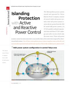
2. System Architecture and Components 2.1. Tested MG The MG of Fig. 1, representing a three-phase four-wire low voltage distribution power system, it is considered in this
work to provide an example of application of the proposed control technique. The MG has ESPC connected at Point of Common Coupling (PCC), single phase loads and single phase PV inverters. The system was developed in Matlab Simulink environment, which allows to evaluate the proposed control approach in various operating conditions with time-domain simulations.
Fig. 1. Tested MG under unbalanced operation.
2.2. Power Converter Topology Power electronic converters are used in MG’s for power conversion and to control the power flow inside the MG and with the main grid [8]. Different types of power converters are needed to perform several functions within a MG. In this paper a four-legs inverter is proposed because the MG consists mixture of three-phase and single-phase inverters
and loads. Four-legs voltage source converter shown in Fig. 2 is used instead of the split DC-link because unbalanced and nonlinear loads cause the neutral currents to flow in the midpoint in the split DC link which can distort the output voltage, moreover the fourth leg allows to fully control of neutral connection, resulting in better output voltage [6, 9].
Fig. 2. Four-legs power converter with LCL filter.
An LCL filter is utilized to achieve low distortion and meeting IEEE 519 harmonic standard. The instability issue associated with an LCL filter is dampened by using a passive damping element [10]. 2.3. Four Legs VSI Modulation Techniques Various modulation techniques have been proposed for switching the 3P4L converter. The Three Dimensional Space
Vector Modulation (3D-SVM) technique was proposed in [11, 12]. It requires complex calculations for the selection of the switching vectors by employing an αβ0 transformation. Carrier-based Pulse Width Modulation (CPWM) is another option [13, 6]. It has been shown that CPWM is equivalent to a 3D-SVM but with an easier implementation. Because of that, it was chosen to be used in this work for converting the reference three signals, from the control loops, into four gating signals for the four-legs inverter.
American Journal of Electrical Power and Energy Systems 2016; 5(4): 28-34
3. Proposed Control Scheme Vector control or (dq) control, can be employed in highperformance three-phase grid connected inverters, for delivering balanced output currents. The AC quantities are easily converted into DC by abc/dq transformation, hence simple PI-type controllers can be employed [14]. However, during unbalanced operation, the measured quantities are containing a double line frequency component due to the negative sequence components and a line frequency component due to the zero sequence components. Therefore it is not pure DC anymore. As well known a Proportional Integral (PI) controller tracks well the desired value if it is pure (DC) [14]. Therefore the decomposition includes symmetrical components can be used to extract the positive, negative and zero sequence components of currents before PI controller [15, 16]. Hence the DC operating point for each
=
sin( cos( +
) )
− cos( ) × sin( )
= 1
+ + +
)
) )
1 ! = #1 " 1
$ $% 1
×
( $% $&× ( ( 1
channel can be obtained without disturbances. Fig. 3 shows the proposed control scheme, it can be seen that the unbalanced currents of MG; I-MG are measured at PCC while the unbalanced currents of ESPC (I-ESPC) are measured at the output of the ESPC in order to control the its output currents [16, 6]. The measured unbalanced quantity of each phase is considered to be the alpha component while the beta component can be obtained by using time delay of quarter period T/4; 5 ms in case of 50 Hz line frequency, which is proposed in [17, 18], this approach is used in this work assuming the MG is connected to a stiff grid operating with a fixed frequency of 50Hz. After getting alpha-beta components of each phase, the conversion from alpha-beta to d-q frame is obtained by using (1). After that the complex form of d-q components are obtained by (2); where the d is the real component and the q is the imaginary component.
Fig. 3. Proposed control scheme description.
(1) (2)
The positive, negative and zero sequence components can be extracted from the three complex quantities as described in (3) and (4). ( ( (
30
+ + +
)' )( ))
(3)
Where u could be V (voltage) or I (current) and a is an
operator and has the value of
$ = * +%,/" , $% = * +/,/"
(4)
The current control loop is used to control the desired sequence components, then a sequence composition is applied by transform each sequence d-q components to alpha-beta as given in (5). =
sin( ) − cos( )
cos( sin(
) × )
(5)
Then equation (6) is used to get three signals in abc reference frame; the inputs of CPWM of ESPC [6].
31
Moien Omar: Control Scheme of Energy Storage Power Converter for Active and Reactive Power Balancing in Grid Connected PV Micro-Grids
1 2 ! − # (& = 1 % 1 ! ) 0− '
%
0
√"
% √"
−
%
1 7 8 16 × # 8 6 15
9
9
8
+8 −8 9
9
9
&
power. As the ESPC interfaces ESS the positive sequence power could be positive, negative and zero. The positive value indicates discharging power from battery while the negative value indicates charging the battery and the zero value indicates that the power converter is working for compensation without delivering or absorbing active power. The transfer function of PI controller in the control loops is given by (7) [6].
(6)
Fig. 4.a shows the negative and zero sequence control loops, both are for compensating the negative and zero sequence components of the unbalanced currents. The reference values are the MG unbalanced currents (I-MG) measured at PCC. The positive sequence power is controlled by the positive sequence control loop, Fig. 4.b, which is used to control the positive output power of ESPC by control the d-q reference values, d for active power and q for reactive
:;< (=) = >? ∗ = +
A
BC D
(7)
Kp=50; Ti=0.025
(a)
(b) Fig. 4. a) Control loop for negative and zero sequence , b) Control loop for positive sequence.
4. Results and Discussions In order to verify the proposed control scheme, the tested cases are assumed with different loads and different generation of single phase PV inverters, connected in each phase of the MG. As ESPC interfaces ESS, this will add
some restrictions and limits in its operation. For example, the battery charging and discharging conditions, should be maintained within the battery manufacturers recommendations, to extend the lifespan of the battery storage system which has high investment costs.
American Journal of Electrical Power and Energy Systems 2016; 5(4): 28-34
32
4.1. Case 1, ESPC Discharging and Compensation Modes This simulation is conducted to evaluate the performance of ESPC control scheme during discharging mode or delivering power with compensation mode, the simulation parameters are tabulated in table 1, where P and Q indicates the active and reactive power respectively. Table 1. Case 1, simulation parameters. Power of local loads, PV and ESPC Power
Phase (A)
Phase (B)
Phase (C)
Load [kW, kVAR]
P=6, Q=3
P=4, Q=2
P=3, Q=0
PV [kW]
P=3
P=4
P=0
ESPC power control Time
Start
0.2 s
Reference power
P=4 kW (delivered)
0.2s
0.4s
P=0 (compensator)
It can be seen in Fig. 5.a, the ESPC is delivering constant active power of 4 kW from starting time until 0.2s, at time 0.2s the output power of ESPC is reduced to 0; compensation mode, ESPC is neither charging nor discharging, as a result the supplied power by the grid is increased by 4 kW, as expected. This can be occurred in cases if the battery state of charge reaches minimum limit or if the Energy Management System (EMS) decides to use the stored energy in different time. Fig. 5.b shows that the reactive power is fully compensated by ESPC throughout the whole simulation period, as a result no reactive power is supplied by the grid.
Fig. 6. Case 1, current wave forms.
Fig. 6.e shows that the grid neutral current (In-grid) is equal zero as expected, because the grid currents are balanced, MG neutral current (In-MG) is circulating in the neutral path. 4.2. Case 2, ESPC Charging and Compensation Modes In this simulation study the ESPC is working in two different modes: charging and compensation, the simulation parameters are given in Table 2. Table 2. Case 2, simulation parameters. Power of local loads, PV and ESPC Power
Phase (A)
Phase (B)
Phase (C)
Load [kW, kVAR]
P=1,Q=2
P=2,Q=3
P=9,Q=0
PV [kW]
P=5
P=4
P=3
ESPC power control Fig. 5. Case 1,active and reactive power.
As shown in Figs. 6.a, 6.b, the three phase current waveforms of MG (I-MG) and ESPC are unbalanced while the grid currents are balanced as shown in Fig. 6.c, because the ESPC compensates the unbalanced of MG. At time 0.2s, the grid currents start increasing because the power supplied by the grid is increased as the power demanded by the MG (6 kW) is delivered only from the grid.
Time
Start
Reference power
P= -6 kW (Absorbed)
0.2s
0.2s
0.4s 0
Fig. 7.a shows ESPC is charging with active power of 6 kW (negative sign), from starting time until time of 0.2s, after time of 0.2s, ESPC is working only as a compensator; it’s output power becomes zero. This can be occurred in some cases when the batteries reach certain fully charged. In Fig. 7.b, it can be seen that, the reactive power of grid remains
33
Moien Omar: Control Scheme of Energy Storage Power Converter for Active and Reactive Power Balancing in Grid Connected PV Micro-Grids
zero, which means it is fully compensated by ESPC.
Fig. 7. Case 2, active and reactive power.
Fig. 8.c shows that throughout the simulation period, the grid current waveforms are balanced with unbalanced waveforms for MG and ESPC currents. At time 0.2s the ESPC stops charging or absorbing power and the grid currents continue to be zero because the power balancing performed by ESPC. Fig. 8.e shows the neutral current for grid is equal to zero, with the same explanation of case 1.
Power balancing is another important advantage of the proposed control scheme, in which the power generated in different phases is distributed to unbalanced loads of the MG. Table 2 illustrates that the sum of PV power generated in the three phases is equal to 12 kW and the sum of the MG local loads is equal to 12 kW also. It can be observed that phase (a) is lightly loaded with high PV generation and phase (c) is highly loaded with low PV power generation. The ESPC distributes the power between phases without discharging ESBs or getting power from the grid. The DC bus of ESPC is charged from phases with power generation greater than consumption, and it delivers that power to phases with consumption greater than power generation. The advantages of distributing power between phases are mainly to improve the efficiency and the reliability of power system. Fig. 9 shows that the charging occurs in phase (a) with high PV generation and discharging that power to phase (c) with high load and low PV generation. The sum of the three power per phase is equal to the output power of ESPC; in the first simulation period the power is negative 6 kW, which means ESPC is discharging with 6 kW, as shown in Fig. 9 the power of phase a, b and c is - 6, - 4 and 4 kW with sum of - 6 kW charging mode. In the next simulation period the total power is zero as power per phase is - 4, - 2 and 6 kW.
Fig. 9. Case 2, ESPC active power per phase.
5. Conclusions This paper represents a control scheme, based on vector control and symmetrical components for a four leg power converter, to mitigate the negative effects of the unbalanced currents and for reactive power compensation in grid connected MGs. The proposed control schemes of the ESPC improves the MGs functionality and flexibility, and obtaining grid friendly MG, operating with highly unbalanced and poor power factor conditions. Results in different cases including power balancing, reactive power compensation with charging, discharging and compensation modes of ESPC are presented to support the validity of the proposed control scheme. Fig. 8. Case 2, current waveforms.
American Journal of Electrical Power and Energy Systems 2016; 5(4): 28-34
References [1]
P. Chiradeja and R. Ramakumar, “An approach to quantify the technical benefits of distributed generation,” IEEE Trans. Energy Conversion., vol. 19, no. 4, pp. 764–773, Dec. 2004.
[2]
R. C. Dugan and T. E. McDermott, “Distributed generation,” IEEE Ind. Appl. Mag., vol. 8, pp. 19–25, Mar./Apr. 2002.
[3]
R. Martinez-Cid, E. O’Neill-Carrillo, “Sustainable microgrids for isolated systems,” Transmission and Distribution Conference and Exposition, 2010 IEEEPES, pp.1-7, 19-22 April 2010.
[4]
M. Omar, and G. Scarcella, “Unbalanced and reactive power compensation for grid friendly microgrids”, 3rd Renewable Power Generation Conference (RPG 2014), 2014 page 3. 3. 3.
[5]
R. H. Lasseter and P. Paigi, “Microgrid: a conceptual solution,” in IEEE 35th Annual Power Electronics Specialists Conference PESC. June 20- 25, 2004, Aachen, Germany. Energy Reviews 24, 387-405.
[6]
Moien. A. Omar, “power converters and control for grid connected microgrids under unbalanced operating conditions” Ph. D dissertation, University of Catania, 2014.
[7]
Modeling, analysis, and design of stationary-reference-frame droop-controlled parallel three-phase voltage source inverters JC Vasquez, JM Guerrero, M Savaghebi, J Eloy-Garcia, R Teodorescu Industrial Electronics, IEEE Transactions on 60 (4), 1271-1280.
[8]
[9]
Y. Wei Li, D. M. Vilathgamuwa, and P. Chiang Loh, “A gridinterfacing power quality compensator for three-phase threewire microgrid applications,” IEEE Transactions on Power Electronics, vol. 21, no. 4, pp. 1021–1031, 2006. Jamil M, Hussian B, Sharkh SM, Abusara MA, Boltryk RJ., “Microgrid Power Electronic Converters: State Of The Art and Future Challenges”, 2009 International Universities Power Engineering Conference (UPEC), Glasgow, United Kingdom.
[10] Design and control of a three-phase four-leg inverter for solidstate transformer applications. Shri, A.; Popovic, J.; Ferreira,
34
J. A.; Gerber, M. B. Power Electronics and Applications (EPE), 2013 15th European Conference on Digital Object Identifier: 10.1109/EPE.2013.6634666 Publication Year: 2013. [11] K. H. Ahmed, S. J. Finney, and B. W. Williams, “Passive Filter Design for Three-Phase Inverter Interfacing in Distributed Generation,” in Compatibility in Power Electronics. CPE, 2007, pp. 1-9. [12] R. Zhang, V. H. Prasad, D. Boroyevich, and F. C. Lee, “ThreeDimensional Space Vector Modulation for Four-Leg VoltageSource Converters,” IEEE Transactions on Power Electronics, vol. 17, No. 3, pp. 314-326, 2002. [13] M. G. Villalva and E. R. Filho, “3-D space vector PWM for three- leg four-wire voltage source inverters,” in Proc. IEEE PESC, 2004. [14] J.-H. Kim and S.-K. Sul, “A Carrier-Based PWM Method for Three-Phase Four-Leg Voltage Source Converters,” IEEE Transactions on Power Electronics, vol. 19, No. 1, pp. 66-75, 2004. [15] M. Reyes, P. Rodriguez, S. Vazquez, A. Luna, R. Teodorescu, and J. Carrasco, “Enhanced Decoupled Double Synchronous Reference Frame Current Controller for Unbalanced GridVoltage Conditions,” IEEE Transactions on Power Electronics, vol. 27, No. 9, pp. 3934-3943, 2012. [16] H. Camblong, I. Vechiu and O. Curea, “An Innovative VSI Controller for the Generation of Balanced Voltage in Spite of the Presence of Unbalanced Loads”, Proceedings of the 2007 American Control Conference, Marriott Marquis Hotel at Times Square, New York City, USA, July 11-13, 2007. [17] E Ortjohann, A Arias, and D Morton. “Grid-Forming ThreePhase Inverters for Unbalanced Loads in Hybrid Power Systems”. In: Conference Record of the 2006 IEEE 4th World Conference on Photovoltaic Energy Conversion (2006), pp. 2396–2399. [18] I. Vechiu, O. Curea, and H. Camblong, “Transient Operation of a Four-Leg Inverter for Autonomous Applications With Unbalanced Load,” IEEE Transactions on Power Electronics, vol. 25, No. 2, pp. 399-407, 2010.