TJPRC: International Journal of Signal Processing Systems (TJPRC: IJSPS) Vol. 2, Issue 1, June 2016, 31-40 © TJPRC Pvt. Ltd.
DECOUPLED ACTIVE AND REACTIVE POWER CONTROL FOR LARGE-SCALE GRID-CONNECTED PV SYSTEMS R.MADHIVADHANA1 &C.CHRISTOBER ASIR RAJAN2 1
PG Student, Electrical and Electronics Engineering , Pondicherry, Engineering College, Puducherry, India 2
Professor, Electrical and Electronics Engineering , Pondicherry, Engineering College, Puducherry, India
ABSTRACT This paper presents a grid connected PV system in large scale with cascaded multilevel inverters. A decoupled active and reactive power control is proposed to achieve power distribution for each PV module, as well as improve the system power quality, overmodulation and reliability.A CFDAB converter implemented specially for its degree of freedom in DC-DC conversion. This system also enhances the independent MPPT for PV system. The control system includes PLL controller, voltage and current controller, voltage distribution and synthesization by which effective reactive power control is achieved. Hence by this system the effective reactive power flow in the PV systems can be eliminated. Finally, a 3MW/12kV system with PV system and cascaded multilevel inverter is simulated in MATLAB and the simulation results are presented to verify the validity of the proposed technology.
Grid Connected Inverter, Decoupling Power Control Technique.
Received: Mar 26, 2016; Accepted: Apr 08, 2016; Published: Apr 18, 2016; Paper Id.: TJPRC: IJSPSJUN20164
I. INTRODUCTION
Original Article
KEYWORDS: Photovoltaic (PV) System, MPPT (Maximum Power Point Traction) High Voltage High Power(HVHP),
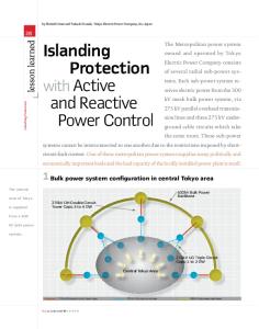
Today photovoltaic (PV) power systems are becoming more and more popular, with the increase of energy demand and the concern of environmental pollution around the world. The power generation by PV system connected to the utility grid has obtained more and more attention, since the world’s demand for clean energy increases very quickly. But the fact that PV arrays cannot be directly connected to the PV inverter in HVHP application due to the PV insulation and ground leakage current issues even if there is low-frequency medium voltage transformer between the PV system and grid, there may be complicated ground leakage current among the PV inverter modules [1-5]. In this paper a Large scale grid-connected HVHP PV system with cascaded PV inverters as shown in Figure 1. The cascaded multilevel inverter is very promising for the HVHP PV system due to its unique advantages such as lower electromagnetic interference, low device rating, improved harmonic spectra, modularity, independent maximum power point tracking (MPPT) for segmented PV arrays, transformer less topology etc. [1][6-8]. In similar way, the cascaded multilevel converters implemented here is CF-DAB dc-dc converter with small DC-link capacitor that can achieve minimized low-frequency ripple effect on MPPT without adding extra components. The current-fed topology with inherit zero-voltage-switching (ZVS) characteristics is particularly suitable for PV application. Furthermore, the interleaved structure is also helpful to alleviate the input power ripple. The cascaded PV system, shown in Figure 1 the total voltage produced is obtained by the output voltage
www.tjprc.org
[email protected]
32
R. Madhivadhana & C. Christober Asir Rajan
from each converter module in one phase leg. This voltage synthesized must fulfill grid codes or requirements for the PV system synchronization. But due to same grid current flows in ac side of each converter module, active power mismatch will happen which will result in unsymmetrical ac output voltage of these modules [9]. The converter with higher active power generation, may cause overmodulation and result in poor power quality if proper control system is not designed for the PV system. The Reactive power compensation will improve the system reliability and help in MPPT for cascaded module during unsymmetrical condition [10]. To maintain the active and reactive power in gridwhen symmetrical active power comes from each module it will be distributed to these modules [11] and [12]. In case of unsymmetrical active power generation this power produced will change in the same direction, this may give output voltage overmodulation in segmented PV arrays. The decoupled active and reactive power control strategy helps to improve the performance of the system, which leads to have good power quality in the grid connected PV system. The reactive power must be controlled in each PV converter to reduce the overmodulation of PV converter output voltage due to unsymmetrical active power from PV arrays. This paper provides a control system where the voltage distribution and current and current control is done which avoids the risk of over modulation and power control in the system.
Figure 1: Large Scale Grid Connected PV System Section II described the system design and parameter analysis is given in table I. The power flow in the system and controller design is illustrated in section III. Simulation verification and results are discussed in section IV and section V with the simulation graphs. Finally, the conclusion is given in section VI.
SYSTEM DESIGN Figure.1 shows the system design for a single phase system this can be implemented for phase b and phase c. Similarly the control system also designed for single phase which can also be used for other two phase.
www.tjprc.org
[email protected]
Decoupled Active and Reactive Power Control for Large-Scale Grid-Connected PV Systems
•
33
CFDAB DC-DC Converter Two stage PV converters with high gain dc-dc converter cascaded by inverter is most popular topology for grid
connected PV system. There are many converters like bulky electrolytic capacitor, dc-link capacitor, voltage-fed dual active bridge dc-dc converter (VF-DAB), etc. Due to many effects such as reduced reliability, large voltage swing, low frequency ripples they are not suited for this proposed system. Design a filter also creates complexity. The CF-DAB dc-dc converter [13] with small DC-link capacitor that can achieve minimized low frequency ripple effect on MPPT without adding extra components. It inherits zero voltage switching (ZVS) characteristics which is particularly suitable for PV application. This converter has two degree of freedom such as the duty cycle D and phase shift angle Φ. The input PV voltage is directly controlled by regulating duty cycle therefore PV array is immune to low-frequency power fluctuation and an optimized MPPT is achieved. The MPPT is achieved by sensing the PV voltage and current. The PV voltage and LVS of dc-link are controlled. Due to an advanced phase-shift control, large voltage ripples are permitted in the dc-link and the dc voltage ripples between primary side and second side are symmetrical, which contributes to reduce the transformer peak current. Table 1: System Circuit Parameters
Furthermore, the interleaved structure is also helpful alleviate the input power ripple. With the proposed
technology, the PV converter can allow the film capacitor to replace the bulky electrolytic capacitors [14]. The v
and to
I Ipv are sensed and MPPT is achieved by P & O method, with the helpof simple PI controller to achieve the duty cycle. The HVS is combined with proportional resonant (PR) to obtain enough gain at double frequency to ensure the
LVS voltage to dynamically follow the reference voltage. With this the required pulse can be generated for the converter. The power transfer from LVS TO HVS is achieved by linear transformer with the help of phase shift angle. The converter can be coupled as n number for the large scale grid connected PV system. For the simulation verification the number of converter is taken as n=4 for a phase. Similarly they can be implemented for b and c phase. The real and reactive power is obtained and measured for each PV system which is decided by individual MPPT attained from each PV System. Thus the dc-dc converter takes PV panel input voltage of around 200Vand produces a boosted output voltage of 3kV which is suitable for the inverter. This happens by the transformer ratio here it is taken as N (transformer turn ratio). The output of converter is feeded to the inverter for dc-ac conversion.
www.tjprc.org
[email protected]
34
R. Madhivadhana & C. Christober Asir Rajan
•
Cascaded Multilevel Inverter The cascaded multilevel is very promising for Large scale PV system. For each converter an inverter is connected
hence for the proposed system n=4 number of single phase inverter is connected to form the cascaded multilevel inverter [19]. This has the main advantage that the reactive power in each module can be synchronously controlled to reduce overmodulationrisk regardless of active power change, by the unique feature of active and reactive power is decoupled in each module by synchronizing with grid current [18]. The switching pattern for the inverter is developed with the help of proposed controller technique. From the cascaded inverter we could able to obtain 9 level output and hence by this ac output is obtained which is synchronized with the grid system which is not implemented in old system [16] and [17]. •
Controller Technique Consider a single phase grid voltage Vga which is fed into the PLL (phase lock loop). The function of this loop is
to hissynchronize on a variable frequency sinusoidal signal. Which produce a vector control dq axis current and angle difference, θ(theta). The DC voltage received from the converter is used to set the reference current. With these the current control for the system can be corporate and required reference dq axis voltage can be obtained. This reference voltage is used for the voltage distribution and synthesization process and by which the phase voltage is synthesized. This can be used to analyze the prior modulation index for the inverter system. With the help of the modulation index the cascaded multilevel inverter can be performed. The PWM (pulse with modulation) technique is used to attain proper sinusoidal waveform. According to the reference and carrier signal in the PWM system the output if the inverter for the proposed system will be 9 levels as the inverter output. By incorporating all these power output and power conversion in HVHP system can be easily done. Thus the power compensation is done to renewable energy based PV system. Where the dc power is converted to ac and synchronized in grid current in the system.
III. POWER FLOW ANALYSIS AND CONTROLLER DESIGN The controller is designed to operate the large scale system in efficient way. To produce pulse for the dc-dc converter the estimated voltage and power from the PV is used and MPP is been tracked. Since we use the CF-DAB system it has dependent in duty cycle and phase shifting with the help of PI and PR controller. •
Reactive Power Estimation The controller technique implemented here is DFT_PLL which is Discrete Fourier transformer. The basic of PLL
is to lock the phase difference [15]. With the help of this controller the single phase grid voltage is been sensed and hence this can be resolved into dq frame by Clarke to park , Transformation as V ga_d and V ga_q Similarly the current can also be resolved to dq axis with rotating frame Iga_d and Iga_q. The reference current is been obtained with the help of different panel voltages such as Vdcna and power such as PPV. The reference current I*ga_d is been extracted from these parameters. The above terms are used to have the components of grid voltage in αβ stationary frame to dq rotating frame can be written as v
v
_α _β
www.tjprc.org
= v sin (Ѡt)
= −v cos(Ѡt)
(1) (2)
[email protected]
Decoupled Active and Reactive Power Control for Large-Scale Grid-Connected PV Systems
v v Ѡ
_
_
=
sin (Ѡt) cos (Ѡt)
−cos (Ѡt) v sin (Ѡt) v
35
_α
(3)
_β
is the system fundamental frequency.
The current control in the controller system is been done with the help of the vector components as derived. This is given in the control system in Figure 2. Where the reference of dq frame the voltages are obtained as Vsa_q* and Vsa_d*. This reference along with theta =t
!
"
#$_%
#$_&
'
(4)
We can convert the dq frame again to αβ frame i.e. rotating to stationary frame. Where the signal for a single phase can be obtained and thus this can be used for inverter pulse generation. Thus the amount of reactive power generated bythe load in the grid system can be estimated by the transformation principle. •
PWM Technique This method is used to generate pulse for inverter according to the reactive power extracted. The modulation
index m1is been obtained by
!
()
. Thus the repeating sequence and the carrier is been implemented to produce the pulse.
For the cascaded inverter (n=4), they require 4 pulse for each inverter system. Hence for the multilevel output accordingly the pulses are generated. Going for higher level will reduce the presence of harmonic in the ac output of the system. The output voltage is been synchronized with the grid system with the help of filter inductor. Whenever there exist a reactive power drop in the grid system there the controller plays a role to overcome these issues. Such that a large scale grid connected PV system can be utilized. The controller is shown in Figure 2. The same is simulated and the result is been analyzed. The same system can be repeated and connected with phase b, phase c. for an effective three phase system. Hence this proves the reactive power compensation in the grid system by the Photovoltaic system with the simulation results. The dc-dc converter has the freedom of duty ratio and phase shifting and hence by calculating PPVna_1 and * +,-._/ 012-._/
we can have the MPPT with the reference VPVna_1*. The PR controller use to avoid double frequency component
and increase the gain ratio. Hence with these the pulse for the converter is been generated. Thus the decoupled active power V ka_d of each module output is obtained by determining the active power contribution. Similarly the reactive power V ka_q of each module is also obtained by determining the reactive power contribution in the system. The output of each module is expressed as
www.tjprc.org
[email protected]
36
R. Madhivadhana & C. Christober Asir Rajan
Figure 2: Control System for Grid Connected PV System v v
_α
_β
=3
sin (Ѡt + −cos (Ѡt +
)
cos (Ѡt + sin (Ѡt +
)
) v 5 ) v
_ _
(5)
K=1,2,3…..n. By using this decoupling effect in the system and the extraction of real and reactive power can be easily understood.This is nothing but the Clarke to park transformation. The Figure 2 shows the details of the controller, with each control units shown separately in the block.
IV. SIMULATION VALIDATION AND RESULTS Large scale grid connected cascaded PV system with the controller is designed and validated in MATLAB. The switching function model in phase a is shown in Figure 3. The same can be implemented for phase b and phase c. From the characteristics of PV array the required current source I PV and voltage source VPV are developed in this model. This can be fed into the controller as shown in control system Figure 2. Then the dc voltage is controlled in converter. Therefore the equivalent current source is given as (! 6) 8
(
(! 6)*7 8
and voltage source
Can be integrated into this model [20]. The dc voltage of converter is determined by both Duty ratio and
phase angle. The inverter output mVdc is connected to grid voltage Vga by grid inductor Lf. The other circuit parameters are listed in table I. Here the reactive power injected into the grid is given as negative power and reactive power absorbed from the grid is defined as positive power. In similar way the active power injected into the grid is positive and the absorbed power is negative. The solar irradiation for n=4 PV inverter module is kept as 200W/m2 or 1000W/m2. At 0.5 sec the irradiation is been change from 200W/m2 to 1000W/m2 [21]. The active power to grid, Pgachanges from 0.178 to 1MW and reactive power to grid, Qga controlled to be -0.5MVAR. The switching of irradiance can be done for different irradiance effect. At 1000W/m2 the active power is seen to be 3MW. The total reactive power to the grid is around -1.5MVAR. When designing for three phase system the switching between the phases can be done in 1 sec. The control implemented used to www.tjprc.org
[email protected]
Decoupled Active and Reactive Power Control for Large-Scale Grid-Connected PV Systems
37
avoid the risk of over modulation. This effective control strategy is used to maintain the active and reactive power and hence helps to improve system performance.
Figure 4: Simulation Results of PV System with Decoupled Active and Reactive Power Control in Phase A
Figure 5: Zoomed Waveform
Figure 3: Equivalent Switching Function Model of the Cascaded PV System in Phase A. www.tjprc.org
[email protected]
38
R. Madhivadhana & C. Christober Asir Rajan
CONCLUSIONS This paper gives the idea of active and reactive power distribution among cascaded PV inverter modules and their impacts on power quality, reliability and system stability for the large-scale grid connected cascaded PV system. The output voltage for each module was extracted based on grid current synchronization, to achieve independent active and reactive power distribution on the system. A decoupled active and reactive power control strategy was implemented to enhance system operation performance. The control strategy enabled the cascaded PV inverter modules to employ their respective reactive power compensation capability regardless of their active power generation. The risk of overmodulation of the output voltage from the cascaded PV inverter modules can be effectively reduced, which improves system power quality and stability. Correspondingly, the simulation and experimental results in Figure 4 and Figure 5 shows the validity proof of decoupled active and reactive power control in the proposed control strategy. REFERENCES 1.
E. Villanueva, P. Correa, J. Rodriguez, and M. Pacas, “Control of a Single-Phase Cascaded H-Bridge Multilevel Inverter for Grid-Connected Photovoltaic Systems,” IEEE Trans. Ind. Electron., Vol.56,No.11, pp.4399-4406, September 2009.
2.
O. Alonso, P. Sanchis, E. Gubia, and L. Marroyo, “Cascaded H-bridge multilevel converter for grid connected photovoltaic generators with Figure 11 Laboratorial PV system hardware prototype including two cascaded 5kW/600V PV inverter modules1307independent maximum power point tracking of each solar array,” in Proc. 34th Annu. IEEE PESC, Jun. 2003, vol. 2, pp. 731–735.
3.
J. Negroni, F. Guinjoan, C. Meza, D. Biel, and P. Sanchis, “Energy sampled data modeling of a cascade H-bridge multilevel converter for grid-connected PV systems,” in Proc. 10th IEEE Int. Power Electron. Congr., Oct. 2006, pp. 1–6.
4.
S. Khajehoddin, A. Bakhshai, and P. Jain, “The application of the cascaded multilevel converters in grid connected photovoltaic systems,” in Proc. IEEE EPC, Montreal, QC, Canada, Oct. 2007, pp. 296–301.
5.
S.J. Lee, H.S. Bae, B.H. Cho, “Modeling and Control of the Singlephase Photovoltaic Grid-connected Cascaded H-Bridge Multilevel Inverter,” Proc. IEEE ECCE, Sep. 2009, vol. 1, pp. 43–47.
6.
L. M. Tolbert, F. Z. Peng, and T. G. Habetler, “Multilevel converters for large electric drives,” IEEE Trans. Ind. Applications, vol. 35, no.1, pp. 36–44, Jan./Feb. 1999.
7.
M. Malinowski, K. Gopakumar, J. Rodriguez and M. A. Perez, “A Survey on Cascaded Multilevel Inverters,” IEEE Trans. Ind. Electron., Vol.57, No.7, pp.2197-2206, July 2010.
8.
L. Liu, H. Li, Z. Wu, Y. Zhou, “A Cascaded Photovoltaic System Integrating Segmented Energy Storages with Self-regulating Power Allocation Control and Wide Range Reactive Power Compensation,” IEEE Trans. Power Electron., vol. 26, no.12, pp. 3545–3559, Dec.,2011.
9.
L. Liu, H. Li, and Y. Xue, “A coordinated active and reactive power controlstrategy for grid-connected cascaded photovoltaic (PV) system in high voltage high power applications,” in Proc. IEEE 28th Appl. Power Electron. Conf. Expo., Long Beach, CA, USA, Mar. 17–21, 2013, pp. 1301–1308.
10. L. Liu, H. Li, Y. Xue, and W. Liu, “Reactive power compensation andoptimization strategy for grid-interactive cascaded photovoltaic systems,” accepted by IEEE Trans. Power Electron., 2014 11. W. Zhao, H. Choi, G. Konstantinou, M. Ciobotaru, and V. G. Agelidis,“Cascaded H-bridge multilevel converter for largescale PV gridintegration with isolated dc–dc stage,” in Proc. 3rd Int. Symp. Power Electron.Distrib. Generation Syst.,
www.tjprc.org
[email protected]
Decoupled Active and Reactive Power Control for Large-Scale Grid-Connected PV Systems
39
Aalborg, Denmark, Jun. 25–28, 2012,pp. 849–856. 12. H. Choi, W. Zhao, M. Ciobotaru, and V. G. Agelidis, “Large-scale PV system based on the multiphase isolated DC/DC converter,” in Proc. 3rd Int. Symp. Power Electron.Distrib. Generation Syst., Aalborg, Denmark, Jun. 25–28, 2012, pp. 801– 807. 13. Wei Song, Member, IEEE, and Brad Lehman, Member, IEEE”Current- fed Dual-Bridge DC–DC Converter” in Proc. IEEE 5th Energy Convers. 14. Y. Shi, L. Liu, H. Li, and Y. Xue, “A single-phase grid-connected PV converter with minimal DC-link capacitor and lowfrequency ripple-free maximum power point tracking,” in Proc. IEEE 5th Energy Convers. Congr.Expo., Denver, Colorado, USA, Sep. 15–19, 2013, pp. 2385–2390. 15. L. Liu, H. Li, and Y. Zhou, “A cascaded photovoltaic system integratingsegmented energy storages with self-regulating power distribution control and wide range reactive power compensation,” IEEE Trans. Power Electron., vol. 26, no. 12, pp. 3545– 3559, Dec. 2011. 16. W. Zhao, H. Choi, G. Konstantinou, M. Ciobotaru, and V. G. Agelidis,“Cascaded H-bridge multilevel converter for largescale PV gridintegration with isolated dc–dc stage,” in Proc. 3rd Int. Symp. Power Electron.Distrib. Generation Syst., Aalborg, Denmark, Jun. 25–28, 2012, pp. 849–856. 17. H. Choi, W. Zhao, M. Ciobotaru, and V. G. Agelidis, “Large-scale PVsystem based on the multiphase isolated DC/DC converter,” in Proc. 3rd Int. Symp. Power Electron.Distrib.Generation Syst., Aalborg, Denmark, Jun. 25–28, 2012, pp. 801– 807. 18. L. Liu, H. Li, Y. Xue, and W. Liu, “Reactive power compensation andoptimization strategy for grid-interactive cascaded photovoltaic systems,” accepted by IEEE Trans. Power Electron., 2014. 19. O. Alonso, P. Sanchis, E. Gubia, and L. Marroyo, “Cascaded H-bridge multilevel converter for grid connected photovoltaic generators with independent maximum power point tracking of each solar array,” in Proc. IEEE 34th Annu. Power Electron. Spec. Conf., Jun. 2003, vol. 2, pp. 731–735. 20. Y. Zhou, L. Liu, and H. Li, “A high performance photovoltaic moduleintegrated converter (MIC) based on cascaded quasi-Zsource inverters (qZSI) using eGaN FETs,” IEEE Trans. Power Electron., vol. 28, no. 6,pp. 2727–2738, Jun. 2013. 21. H. Jin, “Behavior-mode simulation of power electronic circuits,” IEEETrans. Power Electron., vol. 12, no. 3, pp. 443–452, May 1997.
www.tjprc.org
[email protected]