Fall 2010 Meeting 1 Fall 2010 ICC Education Session
Outline • • • • •
Background Overall Process for an Effective Forensic Program Primary Modes of Failure Benefits of a Forensic Program Summary
2 Fall 2010 ICC Education Session
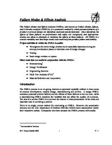
•Cable accessories have a significant Infant mortality rate •Newly installed accessories account for 20% of accessory related service interruptions •Workmanship is the Number 1 cause of failure representing nearly 50% of the total failures •The number of unknown cause of failure is high (about 20%) showing the need for more thorough forensic evaluations
Percentage of Service Interuptions (%)
Background – Significance of Problem Accessories
80
Cable
70 60 50 40 30 20 10 0
New
Middle Aged
Old New Age Description
Middle Aged
Old
•Manufacturing defects represent 15% of the total failures
3 Fall 2010 ICC Education Session
Po o M an r w uf ork ac m a tu rin nsh g i pr p ob M ec le m ha Cor ro ni ca s l D ion am ag e Ev en t Ag i O ng ve r lo a U nk d no M wn oi D st ie ur le e ct ric O th br ea e r C on kdo wn ta m in at io In Ove n co rh M ai r rec eat nt en t re an co ce rd fa ilu re
% of Total Cases
Analysis of Collated Data – Cable Accessories Cause of Failure
Fault Type
40 35 30 25 20 15 10 5 0
Fall 2010 ICC Education Session
4
Analysis of Collated Data – Failures by Accessory Vintage
Accessory Vintages - All Utilities % of Total Failures
40 35 30 25 20 15 10 5
>2 00 5
20 00 -2 00 5
19 95 -2 00 0
19 90 -1 99 5
19 85 -1 99 0
19 80 -1 98 5
19 75 -1 98 0
19 70 -1 97 5
0
Vintage
Joints
Terminations
Junctions
5 Fall 2010 ICC Education Session
Analysis of Collated Data – Cause of Failure Summary by Failure Type ‐ All Utilities
Overall Process for an Effective Forensic Program • • • • • • • •
Preservation of sample integrity Importance of sister components Collection of background information Obtain installation instructions Choose the right evaluation technique/document all findings Identify all installation errors/determine most probable root cause of failure Clearly and accurately report all findings/forward to the appropriate personnel Track results of examinations
7 Fall 2010 ICC Education Session
Preservation of Sample Integrity • Remove sufficient cable length on either side of failed component • Label sample to clearly identify location of failure • Seal cable ends and wrap component to protect from environment • Keep associated components together • Store in a dry location prior to performing analysis
8 Fall 2010 ICC Education Session
Preservation of Sample Integrity • If you do not know what you are doing Do Not attempt your own analysis
9 Fall 2010 ICC Education Session
Importance of Sister Components •
•
•
Sister components are those installed at the same time of the failed component, likely by the same installer Significant damage to failed component may prevent determining most probable root cause of failure Sister components allow for easy detection of installation/workmanship errors if installed by the same personnel
10 Fall 2010 ICC Education Session
Sister Units Jacket Cutback
Jacket Cutback
Copper Tape Shield
Ground Strap Constant Force Spring 11 Fall 2010 ICC Education Session
Sister Units Cut in Cable Insulation at Jacket Cutback
12 Fall 2010 ICC Education Session
Sister Units
Cut in Tape Shield at Jacket Cutback
Copper Tape Shield intact
13 Fall 2010 ICC Education Session
Collection of Background Information • Events leading up to failure (weather, switching events, previous failures, etc.) • Circuit diagram • Number of re-closures on circuit after initial failure • Available fault current • Typical loading conditions • Type of load being served • Any additional information that may be helpful in determining the root cause of failure
14 Fall 2010 ICC Education Session
Obtain Installation Instructions • Obtain installation instructions for vintage of component to be evaluated • A proper analysis of most failed components is the exact reverse of the installation instructions • Check for function, not for detailed compliance • A perfectly installed accessory may fail by means outside the installers control
15 Fall 2010 ICC Education Session
Outside the Installers Control Termite Damage UV Aging
16 Fall 2010 ICC Education Session
Outside the Installers Control Over ¾ inch Total Insulation Shrinkback
12 Inches
17 Fall 2010 ICC Education Session
Choose the Right Evaluation Technique • • • • •
Think before you cut Document all findings/observations through photographs Preserve failure site, Do Not make cuts directly through failure site Cuts should be made at locations 90 degrees on either side of failure site Cuts through failure site should only be made, if necessary, and once a detailed examination of the various mating interfaces has been made Cut through Failure Site
Fall 2010 ICC Education Session
Failure Site
18
X-Ray
19 Fall 2010 ICC Education Session
Identify all Installation Errors/Determine Most Probable Root Cause of Failure • • •
Identification of all installation errors should be documented to enhance training efforts Multiple errors may have contributed to the failure Determine most probable cause by process of elimination through a detailed analysis of the available evidence “When you have eliminated the impossible, whatever remains, however improbable, must be the truth” Sherlock Holmes – In the Sign of the Four
20 Fall 2010 ICC Education Session
Clearly and Accurately Report all Findings •
• • •
•
Report should indentify most probable cause of failure and all installation errors observed Share report with all parties to reduce or prevent future occurrences Discuss product defects with manufacturer to improve processes Discuss installation errors with training personnel or installers to eliminate installation errors If installation errors are the result of unclear installation instructions revise instructions
As-Built of termination used in report
21 Fall 2010 ICC Education Session
Track Examination Results • Results of examinations should be tracked in a database • A database will help responsible personnel to observe and take appropriate action when trends in installation errors or manufacturing defects are evident
Workmanship Lower Cold Shrink Tube Incorrectly Installed at Upper End of Termination
Black Stress Control Tube
Electrical Activity off Insulation Shield Cutback 26 Fall 2010 ICC Education Session
Workmanship Puncture
Incomplete Shrink Down of Dual Layer Tube Leading to Failure
27 Fall 2010 ICC Education Session
Workmanship
Discharge between Inner Stress Control Tube and Cable Insulation Caused by Incomplete Shrink Down 28 Fall 2010 ICC Education Session
Workmanship
Discharge between Inner Stress Control Tube and Dual Layer Tube Caused by Incomplete Shrink Down and Failure to Keep Stress Control Tube Hot
29 Fall 2010 ICC Education Session
Workmanship
Corrosion Deposits No Mastic between Solder Blocks
Lack of Bond between Mastic and Jacket Fall 2010 ICC Education Session
Water Migrated Past End Seal 30
Workmanship
Puncture at Knife Cut in Cable Insulation
Discharge between Stress Control Tube and Insulation Shield 31
Fall 2010 ICC Education Session
Workmanship Interface Tracking from Surface Contamination
32 Fall 2010 ICC Education Session
Workmanship
Water
Dirt Deposits and Lack of Bond
33 Fall 2010 ICC Education Session
Workmanship
Contamination between Insulating Tube and Stress Control Tube
34 Fall 2010 ICC Education Session
Workmanship
Stress Relief Mastic Across Entire Cable Interface
35 Fall 2010 ICC Education Session
Workmanship Brown Discoloration of TRXLPE caused by Overheating Compression Connector
No Wire Brush Marks on Conductor in Area of Crimp Down
36 Fall 2010 ICC Education Session
Workmanship Deformation of Insulation
Thermal Damage to Joint Body
Transition of Insulation Color Away from Connector
37 Fall 2010 ICC Education Session
Workmanship
No Wire Brush Marks on Conductor
Wire Brush Marks on Conductor 38
Fall 2010 ICC Education Session
Workmanship Brown Discoloration of TRXLPE caused by Overheating Compression Connector
Thermal Damage
Tool Cuts in Conductor Strands
39 Fall 2010 ICC Education Session
Workmanship Aluminum Oxides
Arc Pit in Connector Body Area of Crimpdown in Connector Body 40 Fall 2010 ICC Education Session
Workmanship
Bent Probe
Melting of Arc Quenching Probe
41 Fall 2010 ICC Education Session
Workmanship Surface Contamination
Surface Tracking 42 Fall 2010 ICC Education Session
Workmanship Ground Strap
Corrosion Deposits
Soldier Block Located over Dual Layer Tube Fall 2010 ICC Education Session
43
Workmanship Start of Penciling on Cable Insulation Cut in Cable Insulation
Dielectric Puncture
Thin Area of Insulation Wall In Line With Failure 44 Fall 2010 ICC Education Session
Workmanship Note that Cut Aligns with Centerline of Puncture
Fault Channel Electrical Treeing 45 Fall 2010 ICC Education Session
Workmanship Failure Site Bracket Cutting into Cable
Open Neutrals Arcing to Bracket 46 Fall 2010 ICC Education Session
Workmanship Compression Lug Vaporized
47 Fall 2010 ICC Education Session
Workmanship/Manufacturing Knife Cuts Created During removal of Joint Body
White Bedding Tape Sanding Marks
Folds/Wrinkles in Copper Tape
48 Fall 2010 ICC Education Session
Manufacturing Defect
Area of Discoloration
Puncture Site
Puncture Site
49 Fall 2010 ICC Education Session
Manufacturing Defect Void in Insulation
Insulation
Conductor Shield
Puncture in Conductor Shield
50 Fall 2010 ICC Education Session
Manufacturing Defect Fault Channel in Joint Insulation Metal Contaminant
51 Fall 2010 ICC Education Session
Design Issues
Surface Tracking on Cable Insulation
Erosion of Stress Control Tube
52 Fall 2010 ICC Education Session
Design Issues Corrosion on Conductor
Moisture Entry Point
Path of Moisture
53 Fall 2010 ICC Education Session
Design Issue Dielectric Puncture
Cable Training 54 Fall 2010 ICC Education Session
Design Issue Complete Break in Sheath
Failure Site
Stress Cracking
55 Fall 2010 ICC Education Session
Design Issue - UV Aging Surface Tracking and Erosion
Stress Cracking 56 Fall 2010 ICC Education Session
Benefits of a Failure Analysis Program • • • •
Improve Training Reduce outages Increase in revenue Reduce need for expensive diagnostic testing
57 Fall 2010 ICC Education Session
Summary •
•
•
•
Surveys and data analysis show cable accessory failures make up a large percentage of in-service outages About 20% of accessory failures have no known cause, indicating a need for more detailed forensic analysis About 15% of accessory failures can be attributed to manufacturing defects, indicating a need for tighter control of manufacturing processes Surveys and data analysis show the need for improved training of cable accessory installers
Terminations 5.6%
Splices 37.1%
Unknown 1.1%
Cable 56.2%
Utility Survey Showing System Failure Causes
58 Fall 2010 ICC Education Session
Summary All evidence points to improved TRAINING as the single most cost effective means of improving system reliability