International Journal of Current Engineering and Technology
E-ISSN 2277 – 4106, P-ISSN 2347 – 5161 Available at http://inpressco.com/category/ijcet
©2015 INPRESSCO®, All Rights Reserved
Research Article
Failure analysis of Magnetorheological Brake Lijesh K.P.†* and Chiranjit Sarkar‡ †,Mechanical ‡Mechanical
Department, Indian Institute of Technology Delhi, New Delhi, India. Delhi Technological University, Delhi, New Delhi, India.
Accepted 01 April 2015, Available online 07 April 2015, Vol.5, No.2 (April 2015)
Abstract Magnetorheological (MR) fluids alter their flow resistance as a function of the magnetic field. The variation in flow resistance is rapid and completely reversible and due to this MR fluids have been used in Braking applications. In the present paper, a MR Brake experimental setup, developed to evaluate the torque performance of MR brake, has been detailed. The measured torque values were compared with the estimated torque values and errors in the experimental values compared to theoretical torque values as a function of rotational speed have been presented. To investigate the reason for the variations, the vibration of MR disc was measured using proximity sensor. Based on the obtained results from proximity sensor the setup was modified. A comparison among the vibration signals measured on test setups (before modification and after modifications) has been presented. Keywords: MR brake, roller bearing, vibration, torque. 1. Introduction 1 There
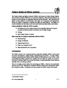
is a trend to replace conventional hydraulic disk brakes with Magneto-Rheological (MR) brake (Sarkar and Hirani, 2015, Sarkar and Hirani, 2013, Sarkar and Hirani, 2013, Sarkar and Hirani, 2013, Sarkar and Hirani, 2013, Sukhwani, Hirani, 2008, Sukhwani et al, 2008, Sukhwani, Hirani, 2008, Sukhwani et al, 2009, Sukhwani et al, 2007). The MR brake, having time invariant friction performance, is an active system and its response is far better than that of hydraulic disk brakes. The MR brake consisting a rotating disk, MR fluid (Hirani and Manjunatha, 2007), electromagnet (core+coil), seals, bearings and housing is shown in figure 1. For developing MR fluid, powder (micro-nano size) of material having high magnetic permeability and saturation (for e.g. iron powder) are used (Sarkar, Hirani, 2013). These particles are dispersed in a nonmagnetic carrier fluid. Seal (Hirani and Goilkar, 2011, Goilkar and Hirani, 2009, Goilkar and Hirani, 2009, Goilkar and Hirani, 2009, Goilkar and Hirani, 2010), brakes are provided to stop the leakage of the fluid from the housing. The bearings (Hirani et al, 1998, Hirani et al, 1999, Hirani et al, 2000, Hirani et al, 2000, Hirani et al, 2001, Hirani et al, 2001, Hirani, 2004, Hirani, 2005, Hirani, Suh, 2005, Hirani, Samanta, 2007, Hirani, 2009, Hirani, Verma, 2009, Lijesh, Hirani, 2014, Lijesh, Hirani, 2015, Lijesh, Hirani, 2015, Lijesh, Hirani, 2015, Muzakkir et al, 2011, Muzakkir et al, 2013, Muzakkir et al, 2014, Muzakkir et al, 2015, Rao et al, *Corresponding author: Lijesh K.P.
2000, Hirani, Samanta, 2007, Shankar et al, 2006, Lords, 2012) are required to bear the load of the flywheel (which provides required inertia to the system).
Fig. 1 Asymmetric Sketch of MR Brake The MR brakes are actuated by passing the magnetic field through the magnetic particles with the help of current carrying electromagnet. On the application of magnetic field, MR fluid changes its state from liquid to semi-solid by aligning magnetic particles in chains. The formation of chain is shown in figure 2. Due to such chaining action, yield strength of fluid increases, friction between disk and housing (Fig. 1) increases and as a result the braking occurs.
1004| International Journal of Current Engineering and Technology, Vol.5, No.2 (April 2015)
Lijesh et al
Failure analysis of Magnetorheological Brake
4 T 2h yd r22 r12 r23 r13 3
(1)
Fig. 2 Chair formation of MR particles with supply of current Sukhwani, Hirani, (Sukhwani, Hirani, 2008) designed a MR brake for high rotational speed up to 2000 rpm. Sukhwani and Hirani (Sukhwani, Hirani, 2008) concluded that, effectiveness of MR brake reduces at high speeds due to shear thinning of MR fluid. Therefore, to make MR brake more effective at higher speed operation, one needs to think of ‘Shear stable MR fluid’. To investigate this phenomenon a MR brake a test setup was developed in the laboratory. Initial study on test setup showed enormous variation between the theoretical and experimental frictional torque values. The measured experimental frictional torque values were higher than the estimated theoretical torque values, which motivated to investigate the test setup. Moreover it was observed that the one of natural frequency of the test setup was close to operational speed of rotating disk. In the present work, experimental investigation is carried out by measuring the displacement of the shaft using proximity sensor at different rotational speed of MR brake and theoretical natural frequency of the system was estimated by using Dunkerley’s method (Budynas, Nisbett, 2011). Based on the obtained results the necessary modifications have been incorporated.
Fig 3 Experimental set for MR brake Where h is the gap between the rotor and housing filled with MR fluid, τyd is the yield stress function of magnetic field, η is the viscosity of the MR fluid, ω is angular velocity of the disk brake, r2 is the outer radius of the disk and r1 is the radius of the shaft as shown in figure 4. To study the braking torque of MR brake, r1=55 mm, r2=196 mm and h=1mm (parameters used to develop MR brake) were considered. The approximate BH polynomial curve polynomial curve (Budynas, Nisbett, 2011) is given by
B 1011 H 2 6 106 H 0.156
(2)
2. Braking Torque The MR brake experimental setup used for the present work is shown in figure 3. It consists of 2 HP DC motor. The speed of the motor is controlled by using the speed controller. A flywheel is mounted between the DC motor and the MR brake through bearing bracket, jaw coupling and flexible coupling. A DC power supply (30 V and 5 A) is used to control the current to the electromagnet of MR brake. The speed of the motor was measured by using tachometer. The experimental torque for the present work was calculated using the instantaneous power drawn from the motor at particular rotational speed. The theoretical torque for the present work is estimated using following formula (Sukhwani, Hirani, 2008, Sukhwani et al 2009, Sukhwani, Hirani, 2008, Sarkar and Hirani (accepted), Sarkar,)
Fig 4 Schematic figure of MR brake The magnetic field intensity (H=NI/2h) of the MR fluid is in kA/m. The estimated values of torque using equation (1) and experimentally predicted values of torque are plotted in the figure 5. From this figure, huge difference between the experimental and theoretical values as a function of operating speed is observed. In the following section the reason for the deviation in torque values has been detailed.
1005| International Journal of Current Engineering and Technology, Vol.5, No.2 (April 2015)
Lijesh et al
Failure analysis of Magnetorheological Brake
Fig. 5 Experimental and theoretical torques
Fig. 8 Rubber padding
3. Results and Discussion To investigate the reason for the variation of the torque, the original setup was modified (as shown in figure 6) to measure the displacement of the disk using proximity sensor.
In the addition to installing rubber pads, the need to regrease the bearings was identified. The grease of ball bearing had become black in color (probably due to impurities) as shown in figure 9(a). After completely de-greasing the bearing, the new lithium based grease was applied as shown in figure 9(b).
Disk
Fig. 6 Modified setup to measure the deflection of disk The deflection data measured at various speeds using the proximity sensor are plotted in figure 7. From this figure it can be observed the lateral deflection of rotating disc is varying between 0.1 mm to 0.18mm. In theoretical calculations, it is assumed that there will not be any lateral deflection of the disc. To reduce the vibration of the system rubber padding (isolation) was provided as shown in figure 8.
(a) Used bearing
Proximity sensor
(b) Bearing with fresh grease
Fig. 9 Bearings used in MR brakes After using the rubber padding and reapplying the grease in the bearing, the displacement signals were measured. The results are plotted in figure 10. From this figure it can be observed that the vibration of the signal has reduced to great extent, hence proving the rubber pad (isolation) and greasing are necessary for MR brake system.
Deflection Amplitude (mm)
0.2 0.18 0.16 0.14 0.12 0.1 0.08 0.06 0.04 0.02 0 200
400
600
800
R.P.M
Fig. 7 Proximity sensor signal at different RPM
Fig. 10 Proximity sensor signal before and after applying greasing and padding at different RPM From figure 10 it is observed that the vibration (deflection) is the maximum at 300-400 RPM. To
1006| International Journal of Current Engineering and Technology, Vol.5, No.2 (April 2015)
Lijesh et al
Failure analysis of Magnetorheological Brake
investigate the reason for such low natural frequency, theoretical study was performed using Dunkerley’s method (Budynas, Nisbett, 2011). This method estimates fundamental critical speed of shaft carrying a number of components (gears (Shah, Hirani, 2014, Hirani 2009), pulley, coupling, etc.). The system is divided into number of subsystems based on components. Using this method critical speed of each individual subsystem is estimate by direct formula. To implement this formula, a block diagram of the MR brake system is shown in figure 11. Fig. 13 Failure of Spiral coupling
Fig. 11 Subsystems and components of MR brake test setup
Due to the low bending stiffness subsystem makes it a weak link. A block diagram of the subsystem 4 is shown in figure 14. The critical frequency estimated for the subsystem 4 having spiral coupling of dimension 60mm length and 40mm diameter, Young’s modulus of 10MPa is 9.13Hz.
In the present system there are total five subsystems. The subsystems 3 is expected to provide more vibration and to reduce the critical speed due to the load of flywheel. To estimate the critical frequency of this subsystem (Fig. 12) following equation is used.
fn
1 2
K M K
Where;
and fn
fn 1 2
(3)
1 2
P
Pl 3 48EI K 48EI l3
and
48E 1 mR 2 Ml 3
4
f
n
1 2
48mER 2 2Ml 3
48 209 109 6 0.0254 2 26 0.2183
f n 1.0514 103 rad / sec f n 167.27 Hz
Fig. 14 Block diagram of subsystem 4 Hence from this theoretical study it is concluded that the spiral coupling has reduced the natural frequency of the system. Hence for any system the spiral coupling should not be used or if it is used then the system must be operated lesser the estimated critical speed or appropriate damping system must be provided to reduce the vibration. Conclusion To evaluate the performance of the MR brake, a test setup was developed and experiments were performed to measure the frictional torque. The comparison in the theoretical and experimental values of frictional torque revealed errors. Detailed theoretical and experimental investigations were performed and it was found the higher system vibration was the reason for such deviations. The vibration in the system is reduced by
Fig. 12 Free body diagram of sub system 3 The estimated natural frequency of the sub system 3 (ω3) using the equation (3) is 167.27 Hz which is very high compared to the natural frequency occurred in the experimental setup (6.67Hz). This indicates that the subsystem 3 is not the reason for providing low natural frequency. The theoretical study was extended to subsystem 4, consisting a low bending stiffness (can be observed from figure 13) spiral coupling.
By providing isolation using rubber padding between the system and foundation Application of proper greasing on the ball bearings. Replacing the spiral coupling with rigid coupling. Acknowledgment This research was supported by Council of Scientific and Industrial Research, New Delhi, India [Grant No. 70(0073)/2013/EMR-II].
1007| International Journal of Current Engineering and Technology, Vol.5, No.2 (April 2015)
Lijesh et al
Failure analysis of Magnetorheological Brake
References Sarkar, C. & Hirani, H., (2015), Development of magnetorheological brake with slotted disc, Proc. IMechE, Part D: Journal of Automobile Engineering, DOI: 10.1177/0954407015574204. Sarkar, C. & Hirani, H., (2013),Theoretical and experimental studies on a magnetorheological brake operating under compression plus shear mode, Smart Materials and Structures, vol.22. no.11, art. no. 115032 Sarkar, C. & Hirani, H., (2013), Synthesis and Characterization of Antifriction Magnetorheological Fluids for Brake, Defense Science Journal, vol. 63, no.4, pp.408-412. Sarkar, C. & Hirani, H., (2013), Design of a Squeeze Film Magnetorheological Brake Considering Compression Enhanced Shear Yield Stress of Magnetorheological Fluid, Journal of Physics: Conference Series, vol.412, no.1, 012045. Sarkar, C. & Hirani, H., (2014), Effect of particle size on shear stress of magnetorheological fluids, Smart Science, http://dx.doi.org/10.6493/SmartSci.2015.317. Sukhwani, V. K., Hirani, H., (2008),A Comparative Study of Magnetorheological-Fluid-Brake and Magnetorheological-GreaseBrake, Tribology Online, vol 3, no.1, pp. 31-35. Sukhwani, V. K., Hirani, H., & Singh, T. (2008), Synthesis and Performance Evaluation of MR Grease, NLGI Spokesman, vol. 71, no.10. Sukhwani, V. K. & Hirani, H., (2008),Design, Development and Performance Evaluation of High Speed MR Brake, Proc. Institute Mech. Engineers., Part L, Journal of Materials: Design and Applications, vol. 222, no.1, pp. 73-82. Sukhwani, V. K., Hirani, H., & Singh, T. (2009), Performance Evaluation of a Magnetorheological Grease Brake, Greasetech India, vol. 9, no.4, pp. 5-11. Sukhwani, V. K., Hirani, H., & Singh, T. (2007),Synthesis of Magnetorheological (MR) Grease, Greasetech India. Hirani, H. & Manjunatha, C. S., (2007),Performance Evaluation of Magnetorheological Fluid Variable Valve, Proc. of the Institution of Mechanical Engineers, Part D, Journal of Automobile Engineering, vol. 221, no.1, pp. 83-93. Hirani, H. & Goilkar, S.S., (2011), Rotordynamic Analysis of Carbon Graphite Seals of a Steam Rotary Joint , Book on IUTAM Symposium on Emerging Trends in Rotor Dynamics, 253-262, Springer Netherlands. Goilkar S S, and Hirani H., (2009) ,Design and development of test setup for online wear monitoring of mechanical face seals using torque sensor, Tribology Transactions, vol. 52, no.1, pp. 47-58. Goilkar, S.S. & Hirani, H. (2009), Tribological Characterization of Carbon Graphite Secondary Seal Indian Journal of Tribology, vol. 4, no. 2, pp. 1-6. Goilkar, S.S. & Hirani, H. (2009) Tribological Characterization of Carbon Graphite Secondary Seal Indian Journal of Tribology, vol. 4, no. 2, pp. 1-6. Goilkar, S.S. & Hirani, H. (2010),Parametric Study on Balance Ratio of Mechanical Face Seal in Steam Environment, Tribology International, vol. 43, no. 5-6, pp. 1180-1185. Hirani, H. & Goilkar, S.S., (2009),Formation of Transfer Layer and its Effect on Friction and Wear of Carbon-Graphite Face Seal under Dry, Water and Steam Environments, Wear, vol. 226, no. 11-12, pp.1141-1154. Hirani, H., Athre, K., Biswas, S. (1998), Rapid and Globally Convergent Method for Dynamically Loaded Journal Bearing Design, Proc. IMechE (UK), Journal of Engineering Tribology, vol. 212, pp. 207214. Hirani, H., Athre, K., Biswas, S. (1999), Dynamic Analysis of Engine Bearings, International Journal of Rotating Machinery, vol. 5, no.4, pp. 283-293. Hirani, H., Athre, K., Biswas, S. (2000), A Hybrid Solution Scheme for Performance Evaluation of Crankshaft Bearings, Trans. ASME, Journal of Tribology, vol. 122, no. 4, pp. 733-740. Hirani, H., Athre, K., Biswas, S. (2000), Transient Trajectory of Journal in Hydrodynamic Bearing, Applied Mechanics and Engineering. vol. 5, no 2. Hirani, H., Athre, K., Biswas, S. (2001), A Simplified Mass Conserving Algorithm for Journal Bearing under Dynamic Loads, International Journal of Rotating Machinery, vol. 1, pp. 41-51.
Hirani, H., Athre, K., Biswas, S. (2001), Lubricant Shear Thinning Analysis of Engine Journal Bearings, STLE, Journal of Tribology Transaction, vol 44, no. 1, pp 125-131. Hirani, H., Athre, K., Biswas, S. (2002), Comprehensive Design Methodology for Engine Journal Bearing, IMechE (UK), Part J, Journal of Engineering Tribology, vol 214, pp. 401-412. Hirani, H. (2004), Multi-objective Optimization of a journal bearing using the Pareto optimal concept, Proc. Institute Mech. Engineers., Part J, Journal of Engineering Tribology, vol. 218, no. 4, pp. 323336. Hirani, H. (2005), Multiobjective optimization of journal bearing using mass conserving and genetic algorithms, Proc. Institute Mech. Engineers., Part J, Journal of Engineering Tribology, vol. 219, no. 3, pp. 235-248. Hirani, H., & Suh, N. P. (2005), Journal Bearing Design using Multiobjective Genetic Algorithm and Axiomatic Design Approaches, Tribology International, vol. 38, no. 5, pp. 481-491. Hirani, H., Samanta, P. (2007), Hybrid (Hydrodynamic + Permanent Magnetic) Journal Bearings, Proc. Institute Mech. Engineers., Part J, Journal of Engineering Tribology, vol. 221, no. J8, pp. 881-891. Hirani, H. (2009),Root cause failure analysis of outer ring fracture of four row cylindrical roller bearing, Tribology Transactions, vol.52, no.2, pp.180-190. Hirani, H., & Verma, M. (2009), Tribological study of elastomeric bearings of marine shaft system, Tribology International, vol. 42, no. 2, pp. 378-390. Lijesh, K. P., Hirani, H., (2014), Stiffness and Damping Coefficients for Rubber mounted Hybrid Bearing, Lubrication Science, vol. 26, no.5, pp. 301-314. Lijesh, K. P., Hirani, H., (2015), Development of Analytical Equations for Design and Optimization of Axially Polarized Radial Passive Magnetic Bearing, ASME, Journal of Tribology, vol. 137, no. 1, (9 pages). Lijesh, K. P., Hirani, H., (2015), Optimization of Eight Pole Radial Active Magnetic Bearing, ASME, Journal of Tribology, vol.137, no.2. Lijesh, K. P. & Hirani, H. (2015), Design and Development of Halbach Electromagnet for Active Magnetic Bearing, Progress In Electromagnetics Research C, vol. 56, 173–181. Muzakkir, S.M., Hirani, H., Thakre, G.D., Tyagi, M.R. (2011), Tribological Failure Analysis of Journal Bearings used in Sugar Mill, Engineering Failure Analysis, vol. 18, no. 8, pp. 2093-2103. Muzakkir, S.M., Hirani, H., Thakre, G.D., (2013), Lubricant for HeavilyLoaded Slow Speed Journal Bearing, Tribology Transactions, vol.56, no. 6, pp. 1060-1068. Muzakkir, S.M., Lijesh, K. P. & Hirani, H. (2014), Tribological Failure Analysis of a Heavily-Loaded Slow Speed Hybrid Journal Bearing, Engineering Failure Analysis, vol. 40, pp.97–113. Muzakkir, S.M., Lijesh, K. P., Hirani, H., Thakre, G.D. (2015) Effect of Cylindricity on the Tribological Performance of Heavily-Loaded Slow Speed Journal Bearing, Proc. Institute Mech. Engineers., Part J, Journal of Engineering Tribology, 2015, vol 229, no.2, pp.178195. Muzakkir, S.M. & Hirani, H. (2015), A Magnetorheological Fluid Based Design Of Variable Valve Timing System For Internal Combustion Engine UsingAxiomatic Design, International Journal of Current Engineering Research, Vol.5, No.2 (April 2015), pp 603-612. Rao, T. V. V. L. N., Hirani, H., Athre, K., Biswas, S. (2000), An Analytical Approach to Evaluate Dynamic Coefficients and Non-linear Transient Analysis of a Hydrodynamic Journal Bearing, STLE Tribology Transactions, vol. 23, no.1, pp. 109-115. Samanta, P., Hirani, H., (2007), A Simplified Optimization Approach for Permanent Magnetic Journal Bearing, Indian Journal of Tribology. Shankar, S., Sandeep, Hirani, H. (2006), Active Magnetic Bearing, Indian Journal of Tribology, pp 15-25. Shah, H. & Hirani, H. (2014), Online Condition Monitoring of Spur Gear, International Journal of Condition Monitoring, vol 4, no. 1, pp.15-22. Hirani, H. (2009), Online Wear Monitoring of Spur Gear, Indian Journal of Tribology, vol 4, no.2, pp.38-43. Lord Corporation, http://www.lord.com/, visited on 20.03.2012. R.G.Budynas, J.K.Nisbett, (2011), Shigley’s Mechanical Engineering Design, Ninth edition, McGraw Hill education (India Private Limited), New Delhi, 2011.
1008| International Journal of Current Engineering and Technology, Vol.5, No.2 (April 2015)