11 Ultrasonic welding of medical plastics H. J. YEH, Amgen Inc., USA
DOI: 10.1533/9780857096425.3.296 Abstract: A technical review of ultrasonic welding for medical plastics is presented in this chapter. The fundamentals of the ultrasonic-heating mechanism are explained followed by a description of the ultrasonic-welding process and process parameters. Key factors affecting the welding process and weld quality are discussed based on practical industrial applications. Selection of medical plastics and impacts of material structure for ultrasonic-welding applications are covered under the weldability discussion. Principles for joint designs and horn designs for ultrasonic-welding applications are explained. The chapter also discusses some approaches for the ultrasonic-welding process optimization and troubleshooting. Finally, the overall advantages and limitations of the ultrasonic-welding process are discussed, and the chapter concludes with an overview. Key words: welding, ultrasonic, medical, plastics, devices, horn design, weldability, joint design.
11.1
Introduction
From low-power ultrasound imaging of prenatal babies to particle dispersion, ultrasound technology has been used in a wide variety of industrial applications for decades. Ultrasonic energy is a form of vibratory energy with a frequency range from 20 kHz to hundreds MHz. One of the key applications of high-power ultrasonic energy is ultrasonic welding. Ultrasonic energy has been used to join both metal and plastic parts in the industry with different heating/joining mechanisms. It has been used in many different industries such as the automotive, medical/healthcare, electronic, packaging, and other consumer-product industries. Since the early sixties when the first ultrasonic joining was used on joining plastics, it has become the most popular joining method for joining plastic parts for different industries including the medical-devices industry. During an ultrasonic-welding process, intense ultrasonic vibrations, applied to the top part through a horn (sonotrode), are used to locally heat and melt the joint interface of the two parts that have been brought into contact under static pressure. When the vibrations stop shortly, the molten 296 © Woodhead Publishing Limited, 2013
Ultrasonic welding of medical plastics
297
plastic solidifies and the parts are welded. The advancements in modern electronic systems and precision-motion control have made ultrasonic equipment more efficient. With all the accumulation of the technical knowledge in horn and part/joint design, the applications of ultrasonic welding have been widened and joint quality made more reliable. Examples of medical devices that use ultrasonic welding are especially abundant in disposable parts, such as a variety of filters and connectors, IV catheters, dialysis tubes, cardiometry reservoirs, hospital gowns, face masks, and sterile garments. This chapter is intended to provide broad and useful information on ultrasonic welding of medical plastics. It covers the fundamental and practical aspects of the ultrasonic welding of plastics and its other joining applications.
11.2
Ultrasonic-welding processes fundamentals
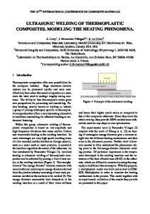
Figure 11.1 shows the essential components for an ultrasonic-welding system. The power supply is designed to generate high-frequency (15, 20 or 40 kHz) electrical energy from standard electrical power (50/60 Hz). The electrical energy is converted into vertical, low-amplitude mechanical vibrations by a piezoelectric transducer. The vibration produced by the piezoelectric transducer is transmitted to the horn through a booster. The booster can be used to amplify or reduce the amplitude of vibration. Booster ratios from 0.6 to 2.5 are usually available for different applications and they are identified by color. The horns used for ultrasonic assembly are generally custom made to suit the application. The purpose of the horn is to properly transmit the ultrasonic vibratory energy to the designated workpiece area so that heating is localized to the joint area. The shape of a horn may be designed to provide additional amplification of the amplitude. The horn is designed to
Power supply Electric energy 60 Hz
15/20/40 kHz Booster
Converter
Piezoelectric ceramic crystal
Horn
Mechanical vibrations
10 µm
�
1:2
booster gain
�
1:3
horn gain = 60 μm
Amplification of amplitude
11.1 Main components for an ultrasonic-welding system.
© Woodhead Publishing Limited, 2013
298
Joining and assembly of medical materials and devices
11.2 Typical bench-top ultrasonic-welding equipment from various venders. (Courtesy of Dukane, Branson, Sonics and Materials.)
Transducer (converter) Pneumatic system Transformer (booster)
Sonotrode Generator and control system Moulded parts
Holding fixture (anvil)
Welding press
Emergency hatch Baseplate
Two-hand safety operation
11.3 Key components of an ultrasonic-welding machine.
deliver the vibratory energy to the workpiece uniformly with minimal stress concentration on itself. Figure 11.2 shows typical bench-top ultrasonic-welding equipments from different venders. The assembly stand/press holds the stack (converter– booster–horn assembly; see Figs 11.3, 11.4, and 11.5) that has to be perpendicular to the anvil. The anvil is a base to provide support for the fixture that holds the part during welding. The fixture provides support for both bottom and top parts to be welded. The bottom part should be fixed and the top part should be aligned with the bottom part yet free to move up and down when
© Woodhead Publishing Limited, 2013
Ultrasonic welding of medical plastics
11.4 Converter booster and horn assembly (the stack) for 20 kHz ultrasonic machine.
11.5 Boosters and horns for 40 kHz ultrasonic machine.
© Woodhead Publishing Limited, 2013
299
300
Joining and assembly of medical materials and devices
Table 11.1 Summary of ultrasonic-welding machine characteristics based on operation frequencies and their applications Frequency
10 kHz
20 kHz
40 kHz
70 kHz
Power rating Amplitude Advantage
4+ kW 100+ μm Powerful, large part Cost, noise
4 kW 50+ μm Good balance Some noise
1 kW 25+ μm Small parts, no noise Part size
100 W 12 μm Very small parts, no noise Part size
Limitation
the horn makes contact with the top surface. A static pressure is applied on the workpieces by the horn through a press system to make sure the ultrasonic energy is transmitted to the workpiece efficiently. The higher the frequency (shorter wavelength) used in the power supply, the lower the amplitude of vibration and power can be generated. Table 11.1 shows the typical machine characteristics and applications for different frequencies. Similar to other plastic-welding processes, there are four fundamental steps in the ultrasonic-welding process – heating of the joint surface, application of pressure, intermolecular diffusion, and cooling (see Chapter 10): 1. Heating of the joint surface is the most critical step during the welding process. Ultrasonic welding has a very complicated heating process. Traditional materials are generally considered as either elastic solids or viscous fluids. Thermoplastic polymers are viscoelastic materials that differ from elastic solids and viscous fluids. When a viscoelastic material is subjected to a sinusoidal (cyclic) strain, the corresponding stress will lag behind the strain by a phase angle. This out-of-phase relationship is referred to as the loss modulus and it is where the energy dissipation/ loss (heating when subjected to ultrasonic vibrations) comes from. In simple energy terms, this can be explained as energy balance in potential energy. For example, when a viscoelastic ball is released to the ground, it bounces back lower than the original height. The bounce-back height is considered as recovered energy that stored in the system (E′, storage modulus) while the difference between the heights is considered as energy loss (E″, loss modulus) (see Fig. 11.6). The relationship between the E″ and E′, can be described by the loss tangent where the δ is the phase angle between the stress and strain. The loss tangent for typical polymer is from 0.001 to 0.5. The higher the loss tangent, the more the energy dissipation during the ultrasonic vibration: tan δ =
E ′′ E′
© Woodhead Publishing Limited, 2013
Ultrasonic welding of medical plastics
301
E�
E�
11.6 Storage modulus vs loss modulus.
11.7 Heating and welding through ultrasonic energy with an energy director at the joint interface.
This loss energy is converted into heat that raises the temperature of the system. The average energy dissipation per unit time or the heat generation rate can be computed using the following equation:1 Q = πfε2E″ where f = frequency ε = strain amplitude E″ = loss modulus – material property This describes the localized heating at the joint interface in the near-field welding situation. Note that the strain (amplitude of vibration) is in squired. This shows that the amplitude of vibration is the most dominant variable in determining the heating rate. Once the melting is generated in the initial contact area, heat is transferred to the surrounding cooler material. Meanwhile the molten material will start to flow and spread over the interface (see Fig. 11.7).
© Woodhead Publishing Limited, 2013
302
Joining and assembly of medical materials and devices
2. Application of pressure is to apply a static pressure onto the top part using a horn to press two parts together to make an intimate contact at the joint interface during welding. Because the viscosity of the molten plastics is high, this step is required for flow and wetting to take place. The molten-plastic flow can be described by the squeeze flow of polymer processing. Ultrasonic-welding process requires a relatively high static pressure during vibration because the heating is generated by relative mechanical motion between two parts. 3. Intermolecular diffusion is similar to the healing of a molten polymer to polymer interface. The key aspect for this step is to let the chain molecules diffuse across the interface to create chain entanglement. Studies have shown that time required for healing is much shorter than the time required for flow and wetting.2 4. Cooling is the step when melted polymer is re-solidified to provide the joint strength. The cooling rate may have some effects on the microstructure of the semi-crystalline thermoplastics. However, for ultrasonic welding, because of the localized heating, only a very short cooling time is needed and a very smaller area is affected.
11.3
Ultrasonic-welding process parameters and control
This section discusses key ultrasonic welding processes and their process parameters. Depending on the different ultrasonic machine vendors, the process control options could vary slightly.
11.3.1
Power requirement
The power requirement is mainly dependent on the size (total area) of the weld and the part material. Also a different frequency of operation offers different amplitude of vibration and power input. As shown in Table 11.1, from 10 to 70 kHz, different frequency ultrasonic-welding equipments offer different-power input and sizes of the part can be welded. Also, semi-crystalline plastics with high melting temperature usually need a higher energy input rate offered by a higher-power machine. Typical welding machines can offer up to 3–4 kW power output for each single transducer. But efforts have been made into combining multiple transducers/ power supplies together to offer more power to weld much bigger size of welds. Specialized digital power generators are required to provide the convertors with the identical acoustical signal. It could potentially offer much higher power output for larger parts.3
© Woodhead Publishing Limited, 2013
Ultrasonic welding of medical plastics
11.3.2
303
Process control
A typical ultrasonic-welding machine offers different control modes of operation. One typical process control is to preset a process parameter value. And when the value is reached, the energy input will stop. Weld time The welding process (ultrasonic energy is activated) will stop when the weld time is reached at the preset level. This is an open-loop control because it is based on the assumption that weld time is proportional to the weld energy. But in reality this relationship only holds when other factors of the welding process are under precise control. Weld energy In a normal ultrasonic-welding process, weld-energy control is a good way to start up and understand a new welding application. The welding process will stop when the weld energy value is reached at the preset level. This is a closed-loop control because the energy level is a good representation of melting, and thus, joint strength. Collapse distance When using collapse-distance control, welding process will stop when a preset collapse distance of the parts is reached. This is also a closed-loop control because the collapse distance of the parts is directly related to the joint quality. This is a good way to control the welding process when the final length of the joined part is critical. For some specific applications, such as insertion or secondary welding operation (two welds on one part), it is necessary to control the collapse distance. In general, weld-energy or collapse control is recommended. But good dimension control of the parts is important for collapse control. More advanced machines allow the user to monitor the above mentioned parameters. The best approach is to preset one control parameter (energy or collapse) and monitor the other two parameters. The other two parameters should consistently be within a limited range. If the other two parameters are far out of range, this usually indicates that problems occurred during the welding process.
11.3.3
Other process parameters
Amplitude of vibration As mentioned in Section 11.2, this is the most dominant parameter to control the heat generation rate. A higher booster ratio increases the amplitude of
© Woodhead Publishing Limited, 2013
304
Joining and assembly of medical materials and devices
vibration, leading to a higher heat-input rate. As a result, the same amount of energy can be reached with less weld time. But on the other hand, the part is more vulnerable to vibratory damage. Some advanced machines allow the user to control the amplitude of vibration during the welding process to control the heating rate to deal with specific challenging semi-crystalline polymers. A higher amplitude of vibration is recommended for semi-crystalline polymers because they require a higher heating rate. Weld pressure/force During the welding process a preset static pressure is applied by the horn/ booster assembly to the top part to maintain an intimate contact at the joint interface. The weld pressure is critical and has to be optimized. If the pressure is too low, heat generation may be erratic and result in a non-uniform weld strength along the weldline. If the pressure is too high, most of the molten polymer may squeeze out from the weld zone or parts may simply jammed together without welding, especially in an interference joint design. Most ultrasonic-welding machines use pneumatic pressure control. New advanced machines use servo motors to control the force and collapse distance more precisely. Some servo-controlled machines are equipped with dual pressure control which allows the presetting of two pressure levels during the welding process. This provides a higher heating rate at the first high-pressure level to initiate melting followed by a second low-pressure level to maintain the melting condition and also keep the molten polymer in the weldline. Trigger force This controls when the ultrasonic energy is activated. When weld force reaches a preset level (trigger force), it triggers the ultrasonic vibration and starts the weld process. Pretriggering is very useful for specific ultrasonic application such as the insertion process. This means the ultrasonic energy becomes active before the horn contacts the parts. If the trigger force is too high, it can ram the parts together and energy may be transmitted through the weld zone down to the bottom part which will result in less melting. Down speed A faster down speed reduces the cycle time, but it needs to be optimized with the weld pressure to make sure the top part is not jammed into the bottom part when an interference joint design is used.
© Woodhead Publishing Limited, 2013
Ultrasonic welding of medical plastics
305
11.3.4 Types of welding process operation Plunge or continuous welding The most common ultrasonic-welding process is plunge welding. The welding process is completed by moving the horn up and down within a small duration time when the actual welding takes place. The parts to be welded can be fed into and removed from the fixture manually or automatically after each welding cycle is completed. Many medical devices, such as filters and connectors, are made in this manner. For continuous-welding processes, the horn is activated continuously and the parts are fed in between the horn and fixture continuously. The most common application is the welding of fabric or film where the weld seam is long and continuous. There are special horn and anvil designs for these specific applications. One or both of them can be rotary shaped. A combination of technical and empirical horn and fixture design processes to achieve the uniform amplitude of vibration and maintain uniform stress level throughout the expected life of the horn and fixture during the production is required to this type of operation. Another special application is the simultaneous sealing and cutting by using a special horn design with a sharp edge. Rotary-table or continuous-conveyer process An automatic-welding production line can be achieved by indexing through multiple stations by either a rotary process or a linear continuous process. A rotary-table process can be designed into several stations such as a parts feeding station, a checking alignment station, a main welding station (or multiple welding stations), and an inspection and reject stations. One key aspect for this design is to maintain the precise alignment of the rotary table during the welding process. If there is an issue with the alignment of the rotary table and the welding station, the weld quality will be impacted. Using a linear continuous process, the process design can be suitable for either conveyor-type operations where the parts (or a continuous web) are fed into the conveyer and the welding stations and inspection stations are in sequence. The main difference is that the parts are carried by a moving fixture on a conveyer in between stations. During the welding process, each part is sitting on an individual fixture that matches the base of the welding station. Therefore, the alignment during the welding is relying on matching each fixture to the base of the welding station. If there are multiple fixtures, it is important to make sure their alignment is consistent in order to produce consistent joint quality.
© Woodhead Publishing Limited, 2013
306
Joining and assembly of medical materials and devices
11.4
Weldability
For general guidelines on the weldability of thermoplastics polymers, please refer to Fig. 10.5 in Chapter 10. Please note that the weldability of ultrasonic welding is more sensitive to other factors like polymer type and joint design.
11.4.1
Material structure and properties
Amorphous vs semi-crystalline Figure 11.8 shows the shear modulus and loss tangent of amorphous polymers over a range of temperatures. Amorphous polymer can maintain a high modulus of elasticity before it reaches the thermoelastic range (around glass transition temperature). This means more ultrasonic energy can be passed to the joint interface rather than being lost inside the polymer. Typical amorphous polymers includes ABS, PS, PMMA, and PC. Figure 11.9 shows the shear modulus and loss tangent (dissipation factor) of semi-crystalline polymers over a range of temperatures. Semicrystalline polymer usually has a higher loss tangent at a low temperature range where the ultrasonic energy is used to heat the amorphous region of
104
2.0 1.8 G´ 1.6 1.4
102
1.2 1.0
101
0.8 0.6
100
Mechanical loss factor, tan δ
Shear modulus G (N/mm2)
103
0.4
Softening range
0.2
Tan δ 10–1 –150 –100
–50
0
50 100 Tg Temperature (°C)
150
0 200
11.8 Shear modulus and loss tangent of amorphous polymer.
© Woodhead Publishing Limited, 2013
Ultrasonic welding of medical plastics 104
307
2.0 1.8 G´ 1.6 1.4
102
1.2 Softening range of the amorphous portions
101
1.0 Softening range of the crystalline portions
0.8 0.6
100
Mechanical loss factor, tan δ
Shear modulus G (N/mm2)
103
0.4 0.2
Tan δ 10–1 –50
0
50
100
150
200
Tg Temperature (°C)
0 250 300 Tm (melting temperature)
11.9 Shear modulus and loss tangent of semi-crystalline polymer.
the semi-crystalline polymer. This means the ultrasonic energy is attenuated inside the polymer rather than transmitted to the joint interface. Figure 11.10 also shows a semi-crystalline polymer that has a distinct melting temperature. It requires a much higher heating rate to get the polymer to melt and to prevent the molten polymer from resolidifying. With a combination of both amorphous portions and crystalline portions coexists in semicrystalline polymers, it makes ultrasonic welding of semicrystalline polymers rather challenging comparing to amorphous polymers. This further explains why semi-crystalline polymers are not recommended for far-field ultrasonic welding applications. Typical semi-crystalline polymers include acetal, nylon, polyester, polypropylene, and polyethylene. Additives Additives, such as transferable mold release agents, plasticizers, lubricants, flame retardants, or impact modifiers usually reduce the weldability of the polymers. Colorants Most colorants do not interfere with ultrasonic welding, but white colorant (titanium dioxide) has a noticeable negative effect on weldability.
© Woodhead Publishing Limited, 2013
Joining and assembly of medical materials and devices
Specific heat
308
Tg
Tm
Temperature
11.10 Glass transition temperature (Tg) and melting temperature (Tm) for a typical semi-crystalline polymer.
Filler materials Minerals, metallic powders, and chopped glass fibers are used to enhance or alter physical properties for the resin. Usually, when the filler content of the resin is less than 10%, it is possible to improve the weldability by increasing its stiffness. But as the content of the filler material increases, the base resin material available for welding is also decreasing. Filler content exceeding 35% may encounter a substantial decrease in weldability. One unique phenomenon that could happen due to the squeeze flow of the molten layer is the unfavorable orientation of the filler material at the joint interface. This could significantly reduce the joint strength in comparison to that of the base material. Moisture Some hygroscopic polymers, such as nylon, polycarbonate, polyester, and polysulfone, if allowed to absorb moisture before welding, may bubble (foamy condition) at the joint area once the water-boiling temperature is reached. This could result in a lower weld strength, a non-hermetic seal, or a poor appearance (porosities). In general, ultrasonic welding produces very localized heating and the impact due to moisture is not as significant compared to that of a large heating area such as hot-plate welding. As a rule of thumb, it is desirable to dry these hygroscopic polymers before welding or to perform the welding as close to the molding process as possible to prevent the parts from absorbing moisture from the environment.
© Woodhead Publishing Limited, 2013
Ultrasonic welding of medical plastics
309
Grade/alloy/blend Different grades of similar polymers may have different melt index and results in flow and wetting problems during the welding process. Alloys and blend polymers may have different melt index and melting temperature which will reduce the weldability between them. Regrind Regrind plastic can be added to the original resin to save material cost. In general, less than 10% of regrind content is permissible. Higher regrind content will reduce the weldability and make the weld strength inconsistent.
11.5
Horn design
Horn design is a complicated process that requires technical knowledge in wave propagation, material properties and accumulation of empirical experience. But with the technological advances in finite element method (FEM) and the availability of huge data bases, horn design has become much easier from a long iterative process. Before getting into the specifics of the horn design, we need to understand the wave propagation on the overall system – from converter to horn. Figure 11.11 shows how the amplitude of vibration changes from converter, booster to horn (vibration system) at a resonant frequency (such as 20 kHz) where the maximum amplitude occurs at the top and bottom surfaces of each component. The length of the components should be at half wavelength of the longitudinal wave to make the vibration system resonant at 20 kHz. The main wave concerned is the longitudinal-wave propagation (up and down vibration in the vertical axis) since it is the direction of the vibration against the parts to be welded. Note that for each component, its total length represents half the wavelength of the wave that propagates in the specific material of each component because the wave propagates differently in different materials. If the length of the horn is not right or the design of the horn is not optimized such that the resonant condition around 20 kHz is not obtained, the whole vibration system may not be in tune (resonant). As a result, the whole system will not be operable because it will overload the electrical system due to the low efficiency. As a result, the horn will need to be rebuilt or modified. The nodal point of each component, where the amplitude is zero, is located close to the longitudinal center of the components but the exact location (shifting up or down from center) depends on the geometry of the specific component. Because of the zero movement (vibration), the nodal point of the converter and booster is usually the place where the ultrasonic machine holds these two components.
© Woodhead Publishing Limited, 2013
310
Joining and assembly of medical materials and devices A0
A0 Converter
A1
A1 Booster
Zone of maximum stress
A2 Sonotrode
Alternative sonotrode
A2 Zone of maximum stress
A3 Amplitude graph
A3
Stress graph
Movement graph
11.11 Amplitude of vibration changes along the stack. (A0, amplitude of vibration entering the converter, A1, amplitude of vibration entering the booster, A2, amplitude of vibration entering the horn, A3, amplitude of vibration at the interface of horn/part)
The booster is usually the component to further increase or reduce the amplitude of the vibration. But the horn itself also can do the job if designed correctly. Figures 11.12 and 11.13 show the rough relationship between the amplitude ratio (gain or reduction) and the top and bottom areas of the horn. This type of estimation is only good for simple geometry. There is a more complicated mathematical relationship that can describe the ratio between the mass of the top and bottom halves and the amplitude of the top and bottom surfaces. When the horn geometry becomes complicated, the amplitude prediction at the bottom of the horn could become a small FEM (finite element method) project. Plate V (see Plate V in the color section between pages 300 and 301) shows the mode of vibration (exaggerated) for a larger horn. In order to make the amplitude of vibration at the bottom more uniform across the whole bottom surface, slots are introduced. Using FEM can precisely predict the size and location of the slots in order to get an even distribution of the vibration at the bottom surface of the horn. It is desirable to have the top surface area of the horn the same or greater than the bottom surface of the booster to obtain a high coupling efficiency.
© Woodhead Publishing Limited, 2013
Ultrasonic welding of medical plastics Tension Compress. Compress. Tension Tension Compress.
Amplitude Amplitude Amplitude
Transducer
0 0 0
311
1 0
Booster
1 0
Sonotrode
2 0 2
11.12 Vibration mechanism of an ultrasonic-welding system (0, nodal points at transducer, booster, horn where the amplitude of vibration is minimal; 1, maximal amplitude of vibration at both ends of the transducer; 2, maximal amplitude of vibration at both ends of the horn).
d1
=
Resonant length λ c = 2 2f
l
l=
=
Amplitude transformation β= d2
d1 d2
2
=
A1 A2
11.13 Resonant length and amplitude relationship (amplitude gain). λ, wavelength; c, velocity of sound; f, resonant frequency; A1, area of face 1; A2, area of face 2.
On the other hand, the bottom half of the horn design is usually determined by the final shape of the joint area or the part geometry. This could become very tricky if only a small portion of the total bottom surface is needed. Sometimes, a hollow horn is used to accommodate a ring shape joint area. When high area/mass reduction of the bottom half of the horn is needed, it is desirable to use a 1:1 ratio or amplitude-reduction booster to avoid an un-tunable situation of the system. FEM is a good simulation tool to make sure the horn design for challenging conditions such as un-tunable situations, uneven amplitude distribution, and high-stress areas can be resolved.
© Woodhead Publishing Limited, 2013
312
Joining and assembly of medical materials and devices Horn
Horn 6 mm
Near field
Near field
11.14 Near-field and far-field ultrasonic welding.
11.15 Thin-wall welding application.
The length of the horn depends on the material of the horn and the frequency of the vibration (wave propagation). Aluminum and titanium are the most popular material for horn construction. For a 20 kHz ultrasonic system, the length of a simple geometry horn for both aluminum and titanium is around 5 inches long. This is close to the half wavelength of the speed of the wave propagation on the particular material of the horn at 20 kHz. By the same token, the horn length for the same material for a 40 kHz is around 2.5 inches. Figures 11.4 and 11.5 show the stack of the converter– booster–horn system with 20 and 40 kHz. We can also understand that the amplitude of vibration of 40 kHz is about half of the 20 kHz. Based on this, we can also understand why 40 kHz is more suitable for smaller parts. On the other hand, a 15 kHz welding machine is capable of handling much
© Woodhead Publishing Limited, 2013
Ultrasonic welding of medical plastics
313
larger parts and offers a higher amplitude of vibration–higher heat generation rate.
11.6
Part and joint design
Part and joint design is critical to the final device product quality. This should be part of the device and process development. It should be considered as a part of the Design for Manufacturing and Assembly processes (DFM/DFA).
11.6.1
Part design
Different welding process requires different considerations during the part-design stage. It is important to design the part with an ultrasonic-welding process in mind rather than try to change the part design after encountering welding problems. Near field vs far field The distance between the location of the joint and the location where the horn contacts the top surface of the part is critical in many applications. If the distance is shorter than 6 mm (1/4″), it is considered near field welding. Otherwise, it is considered to be far-field welding (Fig. 11.14). Near-field welding is always more desirable than far-field welding especially for semicrystalline polymers. In far-field ultrasonic welding, ultrasonic energy needs to travel longer through the polymer where wave propagation and attenuation could both happen. For a semi-crystalline polymer, more ultrasonic energy is attenuated in the far-field situation. As a result, initial heating could happen at the horn and part interface and make it almost impossible to create a joint at the part to part interface. Parallel and uniform contact It is desirable to have a planar joint interface and have it parallel to the horn contact plane. The top surface of the part should have a uniform contact with the horn surface. The joint area should be right underneath the horn’s bottom surface. Stress risers Part design should avoid any potential stress risers. Sharp transitions in geometry, holes/voids, or appendages (tabs, metal attachments, etc.) could concentrate the vibratory energy and create local melting or cosmetic damages to the part.
© Woodhead Publishing Limited, 2013
314
Joining and assembly of medical materials and devices Table 11.2 General guidelines on dimensions and tolerance for joint design Part dimension
Interference per side
Dimension tolerance
1.5″ (35 mm)
(±) 2 mils (0.05 mm) (±) 3 mils (0.075 mm)
Resonance effects (diaphragmming, hot spots/damages, non-uniform melting) When welding a thin-walled structure, the whole part could undergo a resonant vibration. Depending on the part geometry and the frequency, the amplitude of the vibration varies along the walls. As a result, some undesirable melting spots could occur along the walls in addition to the joint area (see Fig. 11.15). In some cases, changes of frequency, amplitude, or horn design can eliminate the problem. But sometimes changes of geometry, such as gate location, wall thickness, or the incorporate ribs and stiffeners, may be needed.
11.6.2
Joint design
Joint design is a very critical step in part design. It should be considered in the part-design stage and incorporated into the molding (or other primary) processes. Typical joint design includes the energy director and the shear-joint designs. The initial contact area between the two mating surfaces should be small to initiate the melting. The contact between the two mating surfaces should be uniform along the whole weld line. Table 11.2 shows some general guidelines for typical joint-design dimensions and tolerances. Considerations In order to select an appropriate joint design, there are some important factors that need to be considered. The following is just a general guideline: 1. Type of plastics: amorphous – energy-director joint; semi-crystalline— shear joint. 2. Weld requirement: hermetic seal – shear joint; appearance—flash trap, tongue and groove joint; high strength requirement—larger joint area; location of the joint – where the ultrasonic energy can efficiently transmit to the joint from horn.
© Woodhead Publishing Limited, 2013
Ultrasonic welding of medical plastics
315
3. Self-alignment: shear joint or tongue and groove joint, or energy-director joint with additional part design (pins, sockets, etc.). 4. Loose-fitting joint: two parts should be free to move vertically with each other. Energy director • • •
butt joint; step joint; tongue and groove.
The energy director is an artificial asperity (triangular-shaped) which is premolded at the bondline for initial melting to occur. This is the joint design that is recommended for amorphous polymers. The angle (apex) that contacts the mating surface can be either a 60° or a 90° angle. A 90° angle is usually good for amorphous polymers, but for high-melt temperature polymers, like polysulfone and polycarbonate, and semi-crystalline polymers a 60° angle is a better choice. Energy-director design could be incorporated with different part designs. Figure 11.16 shows the butt, step and tongue, and groove-energy-director joint designs. Intermittent energy-director joint designs can be used when less joint strength
w 8
w 4 w/8+0.01
w
w
11.16 Typical energy director and tongue and groove joint designs.
© Woodhead Publishing Limited, 2013
316
Joining and assembly of medical materials and devices
11.17 A cross-section of a joint interface from an energy-director joint design.
and non-hermetic joints are needed. Figure 11.17 shows a cross-section of a melted joint interface of a typical energy-director joint design. Shear (interference) Shear type joint designs require an interference between two parts.Therefore, good dimension and tolerance control is critical to the shear joint design in order to produce a consistent joint strength. The welding process will melt the interference continuously (from the lead-in area down along the vertical walls) to prevent resolidification of the molten polymer. Therefore, the shear-joint design is more suitable for semi-crystalline thermoplastics. It is usually self-aligning and is more suitable for hermetic and strong joint requirements. A sufficient wall thickness to provide a rigid sidewall support is critical to prevent the part from deflection during welding. Shear-joint design can be incorporated with different part designs. Figure 11.18 shows some of the different shear-joint designs. One important note for shear-joint design is to avoid a “press-fit” situation from happening during welding. When designing the shear joint, one needs to make sure the wall is rigid enough to maintain the interference rather than yielding to the pressing force and the top part is press fitted into the bottom part and mechanically connected together by press fitting rather than welded together. Figure 11.19 shows a cross-section of a melted joint interface of a typical shear-joint design. Textured surface The textured surface joint design is to have small surface projections molded into the joint surfaces. This is the most effective when used against
© Woodhead Publishing Limited, 2013
Ultrasonic welding of medical plastics
317
11.18 Typical shear joint designs.
11.19 A cross-section of a joint interface from a shear joint design.
an energy-director joint design on the other side of part. It enhances friction and promotes a more uniform melting along the joint interface.
11.7
Process optimization
When a new application is determined to be put into production, welding-process optimization is required to set up the right welding conditions. The optimization process should be conducted on the actual
© Woodhead Publishing Limited, 2013
318
Joining and assembly of medical materials and devices
production environment (machine, horn, fixturing, material, etc.). If there is a change in the production environment, a new optimization process should be performed. The following are typical steps for the optimization process: 1. Approximate condition: Conduct preliminary trials to get the approximate welding conditions. 2. Designed experiments: Select a set of critical welding parameters and responses to run the designed experiments. Typical parameters are: • weld energy (weld time, collapse distance); • amplitude of vibration; • weld pressure; • trigger force; • down speed. Typical responses are: • weld strength; • leakage; • other requirements. 3. Regression analysis: Set up a process model which relates the responses (requirements) to the welding parameters. Once the model is established, graphs showing the optimized welding conditions and relationship between the parameters and the requirement can be generated.
11.8
Other specific applications
Ultrasonic energy can be used for a variety of different applications for joining plastic parts in addition to the regular the welding process. The following are the typical applications.
11.8.1
Staking
The staking process is similar to riveting. Protruding studs which are made on the thermoplastic parts during the injection-molding process are formed into heads using ultrasonic energy. It can be used to join metals to plastics or to join dissimilar plastics. Figure 11.20 shows some typical stake designs.
11.8.2
Insertion
Ultrasonic insertion is a very efficient way to install metal inserts to thermoplastic parts. The bottom surface of the horn should be hardened. Replaceable tips are recommended. The depth of the insertion needs to be controlled (collapse distance control is a good option). The pretriggering of
© Woodhead Publishing Limited, 2013
Ultrasonic welding of medical plastics
319
11.20 Other ultrasonic-welding applications: staking.
Metal insert
Plastic part
11.21 Other ultrasonic-welding applications: insertion.
the ultrasonic energy with a slow down speed, a low amplitude and a low to moderate thruster pressure is recommended. Figure 11.21 shows a typical ultrasonic-insertion operation.
11.8.3
Spot welding
This is very useful when constructing a complex or large structure (with hard-to-reach areas) with sheets of material. Depending on the materials, the thickness of the top layer can be up to about 6 mm or (1/4″) thick. The welding is normally conducted with a hand-held welding unit.
11.8.4
Stud welding
Stud welding is used when moderate weld strength or a non-gas-tight application is needed. A typical stud welding uses the shear joint design. It is also very useful to tack a dissimilar layer in place with a molded rivet.
© Woodhead Publishing Limited, 2013
320
Joining and assembly of medical materials and devices Horn
Rotating anvil
11.22 Other ultrasonic-welding applications: sewing; sealing.
11.8.5
Swaging
Swaging uses ultrasonic energy to melt and reform a ridge (side wall or projection) of plastic to swage it onto a different material. Pretriggering and a high thruster pressure is recommended for this process.
11.8.6
Scan welding: sewing, slitting, sealing
Ultrasonic welding can be conducted in a continuous operation. Scan welding of rigid thermoplastics is possible with self-aligning part/joint designs. Other applications for scan welding are for textile and film bonding, such as sewing, slitting and sealing. These thin thermoplastic materials can be sealed with patterns or edge-sealed (slitting) with two or more layers (woven and/ or non-woven materials). A typical sewing (or continuous sealing) welding operation is shown in Fig. 11.22. Either one or both of the horn and anvil can be in rotary shape. But as mentioned in the welding operation section, designing a rotary horn for a production line is very complicated and will require heavy R&D investment just for the ultrasonic-welding process.
11.8.7
Degating
Ultrasonic degating melts the polymer at the location of sharp profile change. This technique can be used in separation injection molded parts from their runner systems.
11.9
Troubleshooting
Troubleshooting for the ultrasonic-welding process can be difficult because it is a complicated process. The following are the most commonly encountered problems.
© Woodhead Publishing Limited, 2013
Ultrasonic welding of medical plastics
11.9.1
321
Alignment
Good alignment is needed to make sure that the contact between the horn and part and the two part mating surfaces is uniform. Non-uniform contact means non-uniform strength.
11.9.2
Material issues
Polymer grade should be the same in order to insure a good joint quality. If welding is conducted on two parts from different suppliers, one needs to make sure that the resins are the same. Unfavorable additives, fillers or wet polymer situations could reduce joint strength.
11.9.3
Process parameters
Are the parameters optimized? Are there any changes in welding environment (equipment, horn, fixture, etc.) after process optimization?
11.9.4
Part-dimension consistency
Part-dimension consistency is similar to alignment. Inconsistent part dimension could cause inconsistent joint quality. Parts from multi-cavity molding are subjected to dimension inconsistency.
11.9.5
Part/joint design
Is part/joint design fundamentally sound? General considerations for part and joint designs should be followed.
11.10 Advantages and limitations Table 11.1 shows the typical machine characteristics and applications for welding machines with different frequencies. For the medical-device industry, 20 and 40 kHz are the most popular welding machines. It is the most commonly used welding process for medical-device industry. It provides some unique applications where no other welding process can provide with some limitations. Compared with other welding processes, the advantages and limitations are as follows: • •
strong joint (comparable to parent material); short process time (usually less than 1 s);
© Woodhead Publishing Limited, 2013
322 • • • • •
Joining and assembly of medical materials and devices
no new material is required; tolerance of contaminated surfaces; easy for automation; self-cleaning at the joint interface; suitable for different joining application such as staking, insertion, etc.
However, on the other hand, there are also limitations and shortcomings: • • •
it is a complicated process (troubleshooting may be difficult); limitations on size and geometry: thin wall, curved surfaces; limitations on complicated parts where metal components or any loose components are present; • some thermoplastics are difficult to weld (especially in the far-field situation).
11.11 References 1.
2. 3.
Tolunay, M.N., Dawson P.R. and Wang K.K., “Heating and bonding mechanisms in ultrasonic welding of thermoplastics,” Polymer Engineering and Science, Vol. 23, No. 13, Sept. 1983, pp. 726–733. Wool, R.D. and O’Connor K.M. “A theory of crack healing in polymers,” Journal of Applied Physics, Vol. 52, No. 10, Oct. 1981. Herrmann, T. “Ultrasonic twin converter technology for welding large plastic parts or packages,” ANTEC, 2003, pp. 1140–1146.
© Woodhead Publishing Limited, 2013
Plate V (Chapter 11) Simulated mode of vibration of a vibrating horn at 20 kHz.
© Woodhead Publishing Limited, 2013