1/111
Using the Internet Protocol suite to build an end-end IPTV service K.K. Ramakrishnan AT&T Labs Research, NJ USA ITC-2011– Tutorial
© 2007 AT&T Intellectual Property. All rights reserved.
2/111
DISCLAIMER The information provided here is not meant to describe specific AT&T‟s products or services. The content and material herein are entirely based on the opinions and knowledge of the author and are not meant to convey any opinions of AT&T. These slides do not reveal any information proprietary to AT&T Business Units, suppliers, customers or business partners. Most material is based on publicly available information or well-studied networking extrapolations and modeling formulations of public information. The remainder of material is protected by patents or patent applications licensed by AT&T. Page 2
© 2007 AT&T Intellectual Property. All rights reserved.
3/111
A Video Distribution Network based on IP • AT&T has chosen to build a video distribution network on top of an end-end IP infrastructure • Alternative approaches adopted by Cable providers and Verizon with FTTH – Use IP in the backbone, but seek to use the capacity of the access plant downstream to have a Layer 2 environment o Use the bandwidth to distribute channels and depend on “tuning” to access a particular channel
• Having an end-end IP distribution offers both opportunities and challenges – Enables integration of multiple applications; evolving from a linear-TV distribution to content distribution may be easier – Challenges arise: packet loss and recovery; congestion; channel change Page 3
© 2007 AT&T Intellectual Property. All rights reserved.
4/111
IPTV service • High visibility: direct customer impact. • Service is very sensitive to delay and packet loss – Congestion on links -> packet loss-> video quality impairment – Need to tackle multiple failures, which are not very rare – Higher layer mechanisms - FEC, retransmission based recovery of lost packets - can handle (with reasonable delays), burst losses of 50 milliseconds o
Fast restoration is critical
AT&T‟s IPTV service: o
2+ million customers;
o
Triple play: video, internet, and voice Page 4
5/111
Network backbone • One Video hub office (VHO) per metro area
• Broadcast video content is distributed to VHOs using single source sparse mode multicast (PIM-SSM) o
a separate multicast tree for each channel
SHO VHO
VHO
Long Distance Backbone
VHO
VHO
VHO
VHO
VHO
VHO
VHO VHO
S/VHO =
Super/Video Hub Office
Router Metro Intermediate Office Video Serving Office RG
Set-top Box
DSLAM = Digital Subscriber Loop Access Multiplexer
Metro Area
Page 5
Access
RG
RG = Residential Gateway
AT&T IPTV Backbone Distribution InfraStructure 6/111
6
7/111
IPTV Network – Example End-to-End Flow Local content added to national feed via existing multicast groups Content Providers
A-server A-server A-server
National Feed: each channel encrypted over 1 Multicast (PIM) group
D-server D-server D-server
VoDserver VoD-
A-server
Broadband Internet Provider
server R SHO
R
R
R Back office Systems, DBs
R
Metro VHO Analog Voice (evolving to C-VoIP)
Residential Gateway (RG)
VoD, Instant CC, ISP
DSLAM and Serving Office only multicasts channels in use downstream (via IGMP)
RT
DSLAM
Set-top Box (STB)
DS3,OC-n
R/E
E
Serving Office FTTC R = Router; E = Ethernet Switch; R/E = Hybrid GPON = Gigabit Passive Optical Network SHO = Super Hub Office; VHO = Video Hub Office IGMP = Internet Group Management Protocol Page 7
Access Metro
© 2007 AT&T Intellectual Property. All rights reserved.
R Intermediate Office (IO)
P-MP Video Stream P-P Flows (Unicast) 1 or 10 GE/Fiber VDSL/Copper
Backbone Metro
Intermediate Metro VHO OC-48/192 or 10GE
8/111
Some Network Characteristics for Providing IPTV • Streaming video national video stream generally uses MPEG-X for compression/encoding over RTP – Use of IP Multicast (PIM-SSM) when possible from SHO to VHO and VHO to IO enables significant transport cost savings – Ethernet switches use Internet Group Management Protocol (IGMP)snooping to change channels and bridge multicast groups to VLANs
• Perceived video quality is not highly tolerant of loss. Example approach: – L1/L2 protocols restore vast majority of network failures ≤ 50 ms – STB & reliable transport layer protocols to overcome failures ≤ 50 ms
• Instant Channel Change (ICC) popular feature to overcome delay in Multicast group/IGMP change – Typically implemented via Unicast IP flow (point-to-point)
• VoD is usually unicast from VHO to STB Page 8
© 2007 AT&T Intellectual Property. All rights reserved.
What transport service does an app need? 9/111
Data loss some apps (e.g., audio) can tolerate some loss other apps (e.g., file transfer, telnet) require 100% reliable data transfer Timing some apps (e.g., Internet telephony, interactive games) require low delay to be “effective”
Throughput some apps (e.g., multimedia) require minimum amount of throughput to be “effective” other apps (“elastic apps”) make use of whatever throughput they get Security encryption, data integrity, … Application 2-9
10/111
Transport service requirements of common apps Data loss
Throughput
Time Sensitive
file transfer e-mail Web documents real-time audio/video
no loss no loss no loss loss-tolerant
no no no yes, 100’s msec
stored audio/video interactive games instant messaging
loss-tolerant loss-tolerant no loss
elastic elastic elastic audio: 5kbps-1Mbps video:10kbps-5Mbps same as above few kbps up elastic
Application
yes, few secs yes, 100’s msec yes and no
Application 2-10
11/111
Internet transport protocols services TCP service:
UDP service:
connection-oriented: setup
required between client and server processes reliable transport between sending and receiving process flow control: sender won’t overwhelm receiver congestion control: throttle sender when network overloaded does not provide: timing, minimum throughput guarantees, security
unreliable data transfer between sending and receiving process does not provide: connection setup, reliability, flow control, congestion control, timing, throughput guarantee, or security
Q: why bother? Why is there a UDP?
Application 2-11
12/111
Internet apps: application, transport protocols Application
e-mail remote terminal access Web file transfer streaming multimedia Internet telephony
Application layer protocol
Underlying transport protocol
SMTP [RFC 2821] Telnet [RFC 854] HTTP [RFC 2616] FTP [RFC 959] HTTP (eg Youtube), RTP [RFC 1889] SIP, RTP, proprietary (e.g., Skype)
TCP TCP TCP TCP TCP or UDP typically UDP
Application 2-12
13/111
Multimedia Backbone Design: Loss Protection & Failure Restoration Based on work with
Robert Doverspike, Guangzhi Li, Kostas Oikonomou, K. K. Ramakrishnan, Rakesh Sinha and Dongmei Wang AT&T Labs Research, NJ
© 2010 AT&T Intellectual Property. All rights reserved. AT&T, the AT&T logo and all other AT&T marks contained herein are trademarks of AT&T Intellectual Property and/or AT&T affiliated companies. All other marks contained herein are the property of their respective owners.
IPTV Network – Example End-to-End Flow
14/111
Local content added to national feed via existing multicast groups Content Providers
A-server A-server A-server
National Feed: each channel encrypted over 1 Multicast (PIM) group VoDserver VoD-
A-server
D-server D-server D-server Broadband Internet Provider
server R SHO
R
R
R Back office Systems, DBs Metro VHO
Analog Voice (evolving to C-VoIP)
Residential Gateway (RG)
VoD, Instant CC, ISP
DS3,OC-n
RT
DSLAM
Set-top Box (STB)
DSLAM and Serving Office only multicasts channels in use downstream (via IGMP) R/E
R
Serving Office
Intermediate Office (IO)
E
FTTC R = Router; E = Ethernet Switch; R/E = Hybrid GPON = Gigabit Passive Optical Network SHO = Super Hub Office; VHO = Video Hub Office IGMP = Internet Group Management Protocol Page 14
R
Access Metro
P-MP Video Stream P-P Flows (Unicast) 1 or 10 GE/Fiber VDSL/Copper
Metro Backbone
Intermediate Metro OC-48/192 VHO or 10GE
Content Reception and Distribution Content Reception Receive signal transmitted by content producers • Video encoded using H.264/AVC encoders • SD Encoded at 2.1 Mbps with a target of 1.8 Mbps or lower • HD Encoded rate targeted for ~8Mbps or less •
Acquisition Servers (A-Server) at both SHO and VHO locations Encrypts Video and adds DRM • Inserts Metadata •
Distribution Servers (D-Server) at VHO locations Packet Resiliency/Error Correction • Support Instant Channel Change •
VoD Servers (V-Server) •
Page 15
Store encoded and encrypted copies of VoD Movies
15/111
Video Server (D, A servers)
MPEG RTP/RTCP UDP IP Layer 2 (e.g. Ethernet / MPLS)
Video Transport
IP Backbone
Layer 1 (e.g., optical)
Video Client (STB)
MPEG RTP/RTCP UDP IP
16/111
Layer 2 (e.g. Ethernet / MPLS)
Layer 1 (e.g., optical)
Content Acquisition subsystem (A-servers). Packages H.264 encoded stream as Real Time Protocol (RTP) streams. • RTP streams are encapsulated as UDP packets and sent over IP-multicast tree • Also generates a PIP stream for each live TV channel. •
RTP: end-to-end network transport functions for real-time data RTP functions: end-end delivery; payload type identification • sequence numbering (allows receiver to reconstruct sequence) • timestamping and delivery monitoring
•
RTP typically runs on top of UDP to use its multiplexing (by port number) and checksum services. RTCP: RTP Control Protocol allows monitoring of data delivery •
RTCP packets periodically sent from receivers to provide “reception reports”
Digital Subscriber Loop Technology: ADSL and VDSL
17/111
xDSL services are dedicated, pt-to-pt, public network access over twisted-pair copper wire on the local loop ("last mile") ADSL modem on each end of twisted-pair telephone line •
three information channels –
high-speed downstream channel: 6.1 Mbps (@ 9K ft); 1.5 Mbps (@18Kft) •
from service provider’s central office to the customer
medium-speed duplex channel: up to 640 kbps – basic telephone service channel: is split off from digital modem by filters –
VDSL transmits high-speed data over short reach copper •
VDSL part of the FTTN topology for high speed services –
fiber feeding neighborhood optical network units (ONUs) and last-leg connections by copper wire
•
range of speeds also depend on actual line length
•
Max. downstream rate: 51-55 Mbps @1K ft, 13 Mbps@ 4Kft.
•
Upstream rates: 1.6 - 2.3 Mbps
Potential for Packet losses
18/111
Packet loss can occur due to noise on the channel and home network •
A variety of technologies may be supported within the home –
Twisted pair Ethernet, HPNA, wireless
VDSL has FEC with sufficient interleaving to correct errors created by impulse noise events •
Reed Solomon coding; Interleaving introduces delay; FEC overhead ~8%
•
Target packet loss in the VDSL loop and home < 0.1%
•
Not always easy to achieve, especially with varying home network technologies
Recovering from Packet Loss: R-UDP
19/111
Packet loss in the end-end path may occur for a variety of reasons: Loss in the backbone and metro network (bit errors, congestion, link or node failures) • Loss in the last mile (e.g., VDSL, cable plant) • Loss in the home network •
TCP with reliable, flow-controlled, in-order delivery semantics may be overkill •
Mismatched with application requirements for tight latency and jitter
People have been proposing a datagram transport that can meet the needs of real-time applications that can also provide some bound on extent of packet loss, while meeting latency requirements •
Reliable UDP has been proposed as one such protocol enhancement to UDP
Reliable UDP (R-UDP) is used to resend missing packets In the backbone, retransmission requests are uni-cast from VHO (D-server) to SHO and repair packets are unicast from SHO to VHO • In the metro region: retransmission requests and repair packets are uni-cast between D-server and STB •
Client behavior for R-UDP: when STB observes a missing packet •
Reports the dropped packet to the D-server. The D-server then resends the dropped packet.
Details for R-UDP at the Client
20/111
MPEG Client
Playout Buffer
Frame 1
Frame 2
Frame 3
Frame Frame 5 4
Frame 6
Frame 7
Frame 8
Decoder & Player
Deadline playout point
Client has up to some deadline (e.g., 1 second) to recover any lost packets. Any packets recovered beyond this time may be useless •
Deadline determined by the size of the playout buffer/point
The client retry protocol should not report missing packets immediately, since packets may be reordered during delivery. •
Client periodically analyzes what holes it currently has in the RTP stream
•
Reports all or a subset of those holes to the D-Server.
•
The D-Server examines the report and resends missing packets.
D-server has to first recover any packets lost in the backbone from the A-server.
Retransmission Strategy in the Backbone Channel 1 history buffer Retry delivery buffer
Channel 2 history buffer
...
Channel n history buffer
bitrate limit Max Lateness
21/111
• The servers (both the A-server and D-server) have to keep packets (history) around for retransmission • Each VHO (D-server) requests retransmission to fill holes observed • Retransmissions for loss observed by each VHO is typically treated independently
HistoryTime Limit
• Unicast retransmissions use considerable backbone capacity – Even when link failures are restored by local Fast Re-route in 50 ms. o Especially when failure occurs “high-up” in the multicast distribution tree
• Multicast based R-UDP Recovery is very useful to reduce bandwidth requirements for loss recovery
Streamline R-UDP Recovery in Backbone with Multicast
22/111
Servers at the SHO use the multicast tree for transmitting RUDP packets. •
Server reacts to the first R-UDP request for a packet and then suppresses the remaining requests for a period
Multicast R-UDP to gain Efficiency under correlated losses •
Significant reduction in bandwidth consumption on the link from the SHO to the backbone and on subsequent downstream backbone links, and/or a reduction in the number of failed retries compared to unicast.
•
Reduces the processing load on the A-Server
•
With multicast R-UDP, the retransmit bandwidth consumption along the backbone is below a constant factor
•
Unsolicited retransmits must be discarded in the multicast receivers in the VHOs.
This approach removes possibility of R-UDP traffic storm on the backbone •
estimated overhead of about 5% assuming link failure can be recovered in 50 msecs
Multicast R-UDP in the backbone/Unicast on Access 23/111
SHO
A-Server
Mcast source
Multicast R-UDP Multicast on the same tree
BB
PIM
VHO
R-UDP and Depacketizer
PIM
Metro Net, Access Net, RG
STB
IGMP
D-Server
Decoupled R-UDP loops •
Unicast R-UDP STB-DServer
Multicast only to overcome failures on backbone
Servers (SHO and VHO) support multicast R-UDP packet recovery Broad long-term strategy for making IPTv distribution more robust: •
Multicast based recovery of residual losses
•
FEC from SHO server/VHO server to Set-top Box
•
Improved Loss Concealment strategies in media player
Packet Level Forward Error Correction (FEC)
24/111
Physical layer FEC uses Reed-Solomon or Trellis codes for correcting random errors and short bursts Higher level: Packet level FEC uses packet erasure (loss) correction Basically sending extra “repair” packets after sending a block of data packets Each repair packet contains XOR of a subset of data packets Block of data can be recovered if a few more packets than the number of original data packets are received from the combined set Extra bandwidth required ~equal to the maximum packet loss to be protected against Fixed bandwidth requirement – works well for multicast and unicast Can be used to recover from long outages (~200ms) by choosing a larger source block size •
Adds considerable latency
Pro MPEG Forum CoP3 1D FEC
25/111
Good For Low Random Loss Due to BER
D rows
L columns
0
1
2
3
4
5
6
7
8
9
10 11
12 13 14 15 16 17 18 19 20 21 22 23 24 25 26 27 28 29 30 31 32 33 34 35 XOR operations
F0 F1 F2 F3 F4 F5
• Source block composed of LxD source packets numbered in sending order – L x D ≤ 100 – 1 ≤ L ≤ 20 – 4 ≤ D ≤ 20
• Each repair packet is the XOR of the packets in a column
• Overhead = L / (L * D) • 5% Overhead for L = D = 20
repair (parity) packets Page 25
© 2007 AT&T Intellectual Property. All rights reserved.
Pro MPEG Forum CoP3 2D FEC
26/111
Good For High Random Loss Due to BER
D rows
L columns
0
1
2
3
4
5
F‟0
6
7
8
9
10 11
F‟1
12 13 14 15 16 17
F‟2
18 19 20 21 22 23
F‟3
24 25 26 27 28 29
F‟4
30 31 32 33 34 35
F‟5
F0 F1 F2 F3 F4 F5
• Source block composed of LxD source packets • Repair packets calculated across rows as well as columns • XOR Function Used to create repair Packets
• Overhead = (L + D) / (L * D) repair (parity) packets
Page 26
© 2007 AT&T Intellectual Property. All rights reserved.
Multimedia Distribution over IP Backbones
27/111
Media distribution requires significant capacity • With ever-increasing number of multimedia streams to be carried over the backbone: large requirement on capacity –
Over 70% of raw link capacity is needed
System typically organized as: • a small set of centralized content acquisition sites (head-ends); • –
large number of media distribution sites in metropolitan cities;
Redundant set of routers and a number of servers at distribution sites •
a metro and neighborhood area network to reach the home
Use IP Multicast • Using PIM (source specific mode or dense mode) on routers for forwarding –
Tree from source to receivers – on a per “channel” basis for „linear TV‟ •
Typically a group extends all the way to the consumer
Links carry other types of traffic as well
27
28/111
Typical Media Distribution Framework Content provider
other distribution feeds Dual routers per MD
HE
for router protection R 6-1
MD 1
MD 2
Server MD 3
R 6-2
Metro Network
MD 6 MD 4
MD 5
• Each media distribution site: – Distribution servers as well as links have capacity constraints
• Potentially large number of distribution servers at each distribution center
– Failures (of links, routers, line cards, servers) will be the norm • Need to be handled efficiently
28
29/111
Typical IP Backbone
26
25 28
3
5
27
8
9 23
22
1
13
10
6 4
24
16 11
14
2
17
19
7 12
18
20
15
• Nationwide Distribution – Large scale
21
• Large number of routers and distribution servers at each metro area distribution center
– Backbone routers connected via bi-directional IP links form multimedia IP backbone
29
Real-Time Broadcast-Quality Media Distribution: Restoration Issues
30/111
Stringent requirements on packet loss and number of impairments that can be tolerated •
ITU requirements for packet loss for video distribution: less than 10^-8
What can we do in the backbone to relieve pressure on other packet loss recovery mechanisms? Issues/Requirements for IP Backbone restoration: •
Multiple failures in a long distance backbone network are not rare:
–
Multiple failures: over underlying WDM and fiber spans (when not sufficiently diverse) – Need to consider them in a comprehensive manner •
Fast restoration is desirable
•
No congestion during restoration
Environment and Assumptions:
30
•
Network unicast routing protocol: OSPF
•
Network multicast routing protocol: PIM-SSM
•
Restoration process will be eventually carried out and reflected at the IP layer
31/111
Failure Detection and Recovery Detection (Link Layer) •
SONET: alarms
•
BFD: Bidirectional Failure Detection –
Lightweight Hello protocol built on UDP/IP
Quick failure detection possible with OSPF; But…
Recovery •
OSPF: Convergence to new topology can take up to 10 seconds (not uncommon) –
Large IP backbone tends to have parameters set conservatively – PIM-SSM /DM multicast tree converges subsequently •
Link-Based Fast Reroute –
Locally reroute around link failures ("link protection") – Can take 10‟s of milliseconds 31 – Failures become transparent to IP/OSPF perspective
32/111
MPLS secondary LSP tunnel
X
MPLS primary LSP tunnels
MPLS next-hop backup path PHY layer links
X
MPLS next-nexthop backup paths
Example of Fast Reroute backup paths
4-41
33/111
Simple Network Example
• Router-router links (L3 adjacencies) are weighted to work with OSPF and other shortest path protocols • Links are assigned low weights or high weights to control design of the multicast tree (which is generated from the OSPF or IS-IS shortest path tree) • Alternate links are provided for restoration and link weights are also used to control restoration A
D
Bidirectional Link with High OSPF weight
IPTV source Bidirectional link with Low OSPF weight in direction of multicast tree
B C
E
A
D
Multicast Tree B C
E
IPTV source
34/111
Local Link-Based Fast Re-Route Mechanism Normal traffic forwarded on primary link When primary link fails, link layer mechanism using FRR switches to backup No OSPF/PIM-SSM convergence required
A
Backup Path
B
•Each link pre-selects a diverse backup path to create a virtual link •Upon link/interface failure, traffic is rerouted to backup path if the backup is available
“Virtual link” between AB with virtual interfaces Virtual link consists of both a primary and backup
Path: The OSPF topology (and multicast tree) built on top of the virtual link 43
Example of Restoration Methodology
35/111
To meet 50ms target for single L1 failures or distant dual L1 failures • A psuedo-wire is defined between the endpoints of each low-weight link in the direction of the multicast tree in the non-failure state (1-hop MPLS path). • The long distance network is conceptually divided into subnetworks. A given metro network is generally configured as one subnetwork
• A secondary MPLS (back-up path) is explicitly routed over a diverse path within its subnetwork; backup paths from different subnetworks do not overlap • High weight links are placed to serve as links of backup paths. High-weight links do not have backup paths • If only one low-weight link fails – Traffic is rerouted via to the backup path via MPLS forwarding & OSPF LSAs are broadcast for underlying L3 topology – However, the Pseudowire is still active and thus OSPF still sees the PW link as “up” and thus routing tables are unchanged
A
D Backup PW Path
X
B Path from D to A after failure
Primary E C PW Path
Example of Restoration Methodology
36/111
Multiple Failures • If two low-weight links fail – The associated PWs are failed and OSPF sends out “link down” messages – OSPF seeks alternate paths, possibly using the high-weight links
• If link bandwidth is limited, requires careful networks design for complex combinations of above (e.g., node failure in one subnetwork and single link-failure in another) – The backup-path may be active in one subnetwork, yet OSPF reroutes in another subnetwork, possibly (unknowingly) overlapping with backup path A
D
X
B
X
Backup PW Path X
X Primary E C PW Path
A
D
Multicast tree after double failure and subsequent OSPF reconvergence
B C
E
Setting OSPF weights to avoid traffic overlap
37/111
S
d4 (a)
d1
d2
d5
d6
S
d3
d7
Bad weights
d8
d4
d1
d2
d5
d6
GOOD: No traffic overlap under failure
d3
d7
d8
(b) Good weights
• Traffic forwarded using shortest path multicast tree (SSM) • Link weights are set up intelligently so that: • Congestion on the link will likely result in loss and prolonged user-perceived impairment
•Traffic of a backup path and the traffic of multicast tree do not use the same direction along a common link (backup shouldn‟t overlap with the primary) 46
Algorithm to Set Link Weights
38/111
Assumption: •
given a directed network topology with nodes at least 2connected.
Objective:
47
•
Separate the links into two classes: high and low cost links
•
The low cost links form a multicast tree
•
Each low cost link on the tree should have a backup path, which does not overlap with the multicast tree.
Details of the Link Weight Setting Algorithm
39/111
Steps: 1.
Starting from the source, find a series of links to form a ring.
2.
Set a link adjacent to the source as high cost, other links on the ring with low cost. All links with weights form graph G.
3.
From the remaining links, find a series of links, which form a path with two ends of the path (A,Z) staying on G.
4.
Set the first or last link from A to Z on the new path as high cost and other links as low cost.
5.
All links with weights form the new graph G. Repeat the step 3~5 until all links are assigned link weights.
48
Example
40/111
Steps: 1: select ring S-1-5-6-2 3: select path 1-3-5 4: select path 2-8-6 5: select path 3-4-6 6: select path 5-7-8
s
1
3
2 8
5
4
7 Low link weight High link weight
49
6
• After the link weights are set, the low cost links form the multicast tree from S in the undirected graph • Each of these edges is a pair of directed edges • Set the weights of the directed edges along multicast tree to ∞ and others to 1. • Use SPF to generate backup paths for all directed edges along the multicast tree • Details and proof in the paper
Primary and Backup Paths on Backbone Network
41/111
26 25 28
3
5
8
27
9
23
22 1
6
4
13
10
2 1
11
24
16
14
2
17
19
7 12 High cost link Back up path
18
20
15 21
50
Backbone Restoration Approaches
42/111
Alternative 1: Based on IGP Re-convergence only •
OSPF convergence after a failure
•
PIM Multicast tree reconfigures
–
Service hit can be long (driven by OSPF and timers)
Alternative 2: Local Fast Reroute (FRR) •
Each link configured with one backup path; traffic switches to backup path via local FRR upon link failure
–
No OSPF/multicast tree convergence – Less than 50ms recovery
Alternative 3: FRR on failure only until OSPF/PIM reconverge • •
51
Local FRR is utilized only during OSPF convergence period Switch from old multicast tree to new multicast tree afterwards
Alternative 3 Details: Cross Layer Awareness 43/111
Use local fast reroute for restoration of failure; switch to new layer-3 route after OSPF recovers •
Upon a link failure, initiate the Local Fast Re-route to use the backup path
•
However, allow the link failure to be reflected at the IP layer (OSPF) by setting a high cost for the backup path
During OSPF re-convergence process, the backup path is still used for the original tree.
After OSPF convergence, the multicast routing protocol reconfigures the SSM multicast tree
Then use the new multicast tree Similar to RFC 2362 “make-before-break” •
the last hop router of each MD issues a join towards the source along the new shortest path to generate a new tree.
•
The data packets start to flow on the new shortest path tree
•
The receiving router of the backup path prunes the original tree after receiving packets on the new shortest path tree.
•
We now are no longer using the backup path – Minimizes the potential for congestion during the repair interval 52
Potential for Congestion with Multiple Failures
44/111
S
d4
d1
d2
d5
d6
d3
d7
d8
• Even
with proper weight setting, multiple concurrent failures may result in congestion • Alternative 3 improves this situation by using the backup paths only for a short period • Backup paths are utilized only until OSPF reconverges tree is reconfigured 53
and multicast
Performability Analysis
45/111
We have developed a tool called “nperf” nperf evaluates the combined performance and reliability (performability) of networks.
•
Usually they are analyzed separately, by different tools.
•
Reasons for Performability Analysis: Performance: get the performance in the “perfect” state of the network. – Reliability: shows that the network structure is “OK” – but not enough to ensure good performance. –
•
Performability: see the performance in all possible network states (failure scenarios), including multiple simultaneous failures. –
54
Understand even the penalty of rare, but high-impact events
Performance under failure conditions
46/111
Designing a network for good performance in the absence of failures better understood. •
Usual approach when there is limited extra capacity: –
look at a selected set of single (and maybe double) failures; patch the design to tolerate specific failures.
nperf –
Systematically explores as much of the failure space as possible, – Finds bounds on the performance metrics on the unexplored part of the space, – Ranks the failure scenarios according to importance.
In every network state nperf computes two main metrics: •
Traffic lost because of no route,
•
Traffic lost because of congestion.
•
Computes average (expected loss), and probability distribution
55
Comparison: Service Impact Minutes Alternative 1
downtime minutes per year
300
Alternative 2
47/111
Alternative 3
250 200 150 100 50 0 1
2
3
4
5
6
7
8
9 10 11 12 14 15 16 17 18 19 20 21 22 23 24 25 26 27 28 node ids
• Significant downtime across all the nodes (MDs) with Alternative 2 (FRR)
• The time is dominated by the time period for repair • Alternative 1 also has a lot less downtime than Alternative 2 • Alternative 3 improves the situation substantially – in many cases, downtime is negligible 56
service impact events per year
Comparison: Service Impacting Events Alternative 1
100 90 80 70 60 50 40 30 20 10 0 1
2
3
4
5
6
7
8
Alternative 2
9
48/111
Alternative 3
10 11 12 14 15 16 17 18 19 20 21 22 23 24 25 26 27 28 node ids
• The number of service impacting events is highest with Alternative 1. • OSPF re-convergence and multicast tree reconfiguration more frequent • Substantial improvement in the number of service impacting events with
Alternative 2 (local FRR) and Alternative 3 57
Multiple Failures
49/111
None of the existing approaches can reasonably handle multiple failures. • •
Multiple failures can cause FRR traffic to overlap. PIM must be informed about the failures and should switchover to the new tree as soon as it is possible. So that overlaps due to multiple failures are minimized. No single failure causes an overlap. Multicast source But a double failure does.. 2 –
1
0
1
3
1
1
1
4
Old tree before failures
1 3
59
5
3
FRR path for 1-3 FRR path for 1-2
Our Approach: FRR + IGP + PIM
50/111
Key contributions of our approach: • •
Layer 2
Layer 3
•
It guarantees reception of all data packets even after a failure (except the packets in transit) – hitless It can be initiated when a failure is detected locally by the router and does not have to wait until routing has converged network-wide – works with local rules It works even if the new upstream router is one of the current downstream routers – prevents loops during switchover
60
Multicast protocol (e.g., PIM-SSM) IGP routing (e.g., OSPF) FRR support (e.g., MPLS)
Routing changes
Link failure/recovery
IGP-aware PIM: Key Ideas
51/111
Our key ideas as “local” rules for routers: minimal additional Rule #1: Expose link failure to IGP routing even Very though FRR backup path multicast state. is in use. Rule #2: Notify multicast protocol that IGP routing has changed so that it can reconfigure whenever possible. •
PIM will evaluate and see if any of its (S,G) upstream nodes has changed. If so, it will try sending a join to the new upstream node. Two possibilities: – –
•
#2.a New upstream node is NOT among current downstream nodes Just send the join immediately. #2.b New upstream node is among current downstream nodes Move this (S,G) into “pending join” state by marking a binary flag.
Do not remove the old upstream node’s state info yet.
Rule #3: Prune the old upstream only after data arrives on the new tree. Send prune to the old upstream node when you receive a data packet from the new upstream node. • Remove the old upstream node‟s state info.
•
Rule #4: Exit from the transient “pending join” state upon prune reception. •
When a prune arrives from a (currently downstream) node on which there is a “pending join”, then: – –
61
Execute the prune normally. Send the joins for all (S,G)s that have been “waiting-to-send-join” on the sender of the prune.
IGP-aware PIM Switchover: A sample scenario, No FRR yet
52/111
62
New tree after failure Old tree before failure
Multicast source
2
5
0 1
5
1
Node 4:
3
1
1
detects the routing change after SPF and tries to send a join message to 2 (#2)
4
1
1
moves to “pending join” state (#2.b)
5
hears about the failure via IGP announcements and does SPF detects the routing change after SPF and tries to send a join message to 1 (#2)
sends the join to 1 (#2.a) but does not install the 21 interface yet
receives data packets from new tree and sends a prune to old upstream node (#3)
Node 4:
receives the join message from 2 adds the 12 downstream interface and data starts flowing onto the new tree
Node 2:
Node 2:
Node 1:
receives prune from 2 and moves out of “pending join” state by sending the join to 2 (#4) processes the received prune
Node 2:
receives the join message from 4 adds the 24 downstream interface and data starts flowing onto the new tree
FRR Support Congested Common Link
53/111
When there is FRR support, common links (i.e., overlaps) may happen. Common Link (CL):
During a switchover, the new tree might overlap with the FRR path of the link that failed.
Multicast source
2
5
0 1
1
5
1
CL: Common Link 4
1
5 New tree after failure
1 3
1
Old tree before failure
Issue: Congested Common Link •
CL might experience congestion and data packets on the new tree (blue) might never arrive at node 4
Solution: Allow CLs, but prioritize the traffic on the new tree •
63
After link failure, mark the data traffic on the new tree with a higher priority and FRR packets with lower priority.
Summary
54/111
Protection and Restoration approaches for an IP backbone must understand the impact of failures and the interactions across the protocol layers Restoration approaches in an IP backbone used for multimedia distribution have to be carefully designed •
To maintain user perceived quality
We look at combination of network design and restoration algorithms to •
ensure fast restoration to minimize impact of failure events
•
avoid congestion during multiple failures, because –
Multiple failures have high impact – Repair times can be significant
nperf – tool to comprehensively analyze performance and reliability of network for all failure events We use a combination of a local fast-reroute mechanism (for quick restoration) and switching to the multicast tree based on the new topology (to avoid congestion in the event of subsequent failure). 64
Proactive Network Management for the production IPTv System
© 2010 AT&T Intellectual Property. All rights reserved. AT&T, the AT&T logo and all other AT&T marks contained herein are trademarks of AT&T Intellectual Property and/or AT&T affiliated companies. All other marks contained herein are the property of their respective owners.
55/111
Our approach
56/111
•
Be proactive in dealing with the effect of multiple failures
•
Maintenance activity is often planned far in advance and is often agnostic to real-time network state We coordinate planned network maintenance activity with real-
•
time network state.
• Need a comprehensive view across many different network layers. •
Example (details later): an SNMP based tool can tell when a link
is congested but by looking at a variety of data sources, we can pinpoint to one of 3 or 4 different reasons for link congestion.
Dealing w/ Network component failures
57/111
• (Reactive) Use FRR whenever backup path is available; Use IGP otherwise. There is potential for congestion with multiple failures overlap of two FRR paths, OR • overlap of FRR path with multicast tree. •
• (Proactive) Avoid potential overlap by using a cross-layer approach to reconfigure the multicast tree after a successful FRR event. [COMSNETS 2010] Another issue: Alert the operator to any changes in network state. E.g, • An FRR event may reroute traffic to a different set of links • A PIM re-convergence may alter the multicast tree
Dealing w/ Network maintenance
58/111
Maintenance activity is often planned far in advance and is
•
often agnostic to real-time network state •
Coordinate planned network maintenance activity with real-time network state.
•
Examples:
•
any link carrying traffic should not have a maintenance activity
•
IPTV networks are typically shared as an access network providing Internet connectivity to customers and a pair of routers within a metro office maintain BGP sessions with ISP edge routers. If one of these BGP sessions is down, its „mate‟ router should not be touched.
Pinpoint the cause of link congestion
59/111
• An SNMP based tool can point out which links are
congested. However knowing the underlying cause can for congestion gives an insight in how to fix it. • Holistic view needed to disambiguate cause
• Different ways that a link can get congested •
Oversubscribed? Too many TV channels/VoD
•
Overlap between different FRR paths and/or multicast tree
•
Lots of parallel links between offices and sometimes we can get load imbalance: high bandwidth channels on one link and low bandwidth channels on the other link.
Web based visualization tool: Birdseye
60/111
Synthesizes and interprets data from a variety of data sources to obtain a comprehensive network view. Our overall philosophy is to
• Maintain an idealized, failure-free state –
List of links and routers, link capacities, multicast tree, FRR backup paths, etc.
• Maintain real-time state – –
Real-time topology, link utilization, BGP reachability, database of links planned for scheduled maintenance Either directly from tools or by interpreting data from multiple tools.
• Parse the differences and show necessary alerts to the operator • Has been in use in AT&T Network Operations Center for 1+ yr.
Data Sources
61/111
• NetDB tool (developed at AT&T Research): parses router configuration files to build failure-free topology • OSPFMon tool (developed at AT&T Research): establishes a partial adjacency with one or more routers to receive LSAs and create a real-time topology • FRR is invisible to IGP and may appear self-healing but it alters the network state significantly Need logic to infer that successful FRR has happened – Use NetDB to get links in the back-up path being used –
• MRTG tool: collects link utilizations • BGP reachability: compare number of routes to a threshold; also monitor various alarms • Operations Support System: list of links scheduled to undergo maintenance during the next 24 hours.
Sample GUI snapshot: triple link failure
TO PROTECT PROPRIETARY INFORMATION THIS DOES NOT DEPICT AN ACTUAL NETWORK OR OUTAGE
62/111
Sample snapshot: updated multicast tree
63/111
TO PROTECT PROPRIETARY INFORMATION THIS DOES NOT DEPICT AN ACTUAL NETWORK OR OUTAGE
Summary
64/111
• IPTV services have high sensitivity to impairments and high visibility in terms of customer impact
• Need careful designing of network protocols to deal with multiple failures • Operators need a comprehensive view of the network •
Our Birdseye tool distills network data from multiple AT&Tdeveloped systems and public tools and domain knowledge of networking protocols to compile a holistic view to the operators
•
Has been in use at Network Operation Center for over a year for a service with 2+ million customers
65/111
Scalability Issues for Live Broadcast Television Distribution Module 6 K. K. Ramakrishnan AT&T Labs Research, NJ
© 2010 AT&T Intellectual Property. All rights reserved. AT&T, the AT&T logo and all other AT&T marks contained herein are trademarks of AT&T Intellectual Property and/or AT&T affiliated companies. All other marks contained herein are the property of their respective owners.
“Instant Channel Change”
66/111
When a user requests a new channel, the STB has to eventually join the multicast group for the new channel Native IP multicast for IPTV through IGMP join and leave has to complete •
but “joins” take only a few milliseconds, so what is the problem?
Channel changes in packetized environment are relatively slow because •
STB has to wait for an I-frame and start buffering from that point
•
Requires pre-buffering up to playout point before playing live video
The buffering of video in the playout buffer up to a “threshold” (1-2-3 seconds (configurable)) implies playout of live content needs to catchup •
Playout buffer threshold (playout point) set conservatively to allow for recovery of lost packets – e.g., using R-UDP.
•
May be main source of “jitter”, especially with lossy links
Instant channel change mechanisms have generally used an initial speed up for delivery of video to STB Ref: Multicast Instant Channel Change in IPTV Systems, Damodar Banodkar, K.K. Ramakrishnan, Shivkumar Kalyanaraman, Alexandre Gerber, Oliver Spatscheck, in IEEE Comsware 2008, Jan. 2008.
Unicast Channel Change
67/111
D-Server caches video frames in a circular buffer On receiving a channel change request, D-Server unicasts cached video frames, starting with an I-frame •
D-server transmits at an accelerated rate
When D-server has sent all the content in its buffer, the client STB has very likely caught up to the "live" stream •
Client issues a join, and D-server only multicasts new data at nominal bit-rate
Unicast lasts for a “fixed” time interval The mechanism is based on channel change events being relatively uncorrelated Simple optimization is to make this dynamic •
Wait for client playout buffer to fill up to playout threshold
•
Switch to multicast
TV Channel Selection (Unicast)
68/111
A-server
R SHO
R
D-server VHO
Page 78
7. VSO does similar IGMP snooping as in DSLAM (+ “fast leaves” & serves as proxy for reports & queries) IO CO R
R
DSLAM
DSLAM
1. Customer changes from channel m to n
DSLAM DSLAM
DSLAM DSLAM
4. D-server receives ICC request & 3. DSLAM forwards all transmits (unicast) ICC packets directly sped-up channel n between IP address of to STB for X STB and D-server. seconds 6. DSLAM snoops packets for IGMP messages and updates its IGMP table for each STB (drop m, add n). If already receiving channel n from VSO, it replicates to STB on its private VLAN, else it forwards IGMP request to VSO (+ serves as proxy for reports & queries) © 2007 AT&T Intellectual Property. All rights reserved.
Residential Gateway (RG) Set-top Box (STB)
2. STB sends ICC request for channel n directly to D-server 5. If customer watches chan n for > X- secs, STB sends IGMP “leave” and “join” packets to the IO router ICC unicast flows IGMP leave/join messages Multicast TV channels
69/111
Enhanced Unicast ICC operation VHO : Video Head End IO: Metro Network Routers CO: Central Office DSLAM STB: Set Top Box
VHO
Server
IO
CO Bandwidth and Scalability Concerns: Bandwidth requirement and queueing at bottleneck links between D-server and STB
DSLAM
STB_1
Increases with number of end users (changing channels concurrently) increases When a number of users need to be served by the single channel: server capacity limits (typically few servers to stream a given channel)
STB_2 Buffer
Buffer Join for Mcast Group Page 80
Join for Mcast Group © 2007 AT&T Intellectual Property. All rights reserved.
Difficulties with the Unicast ICC
70/111
• Unicast ICC reduces channel change time, but comes at a cost
• When there are concurrent ICC requests, there is a substantial load on the network, – especially on the link between the DSLAM and the CO, which normally acts as a bottleneck link.
• D-Server also has to support large number of unicast streams – Each D-Server has a given I/O capacity that it can handle
• When a number of users need to be served by the same channel: server capacity limits – Server may be assigned on a per-channel basis, incurring further cost for the service provider
Page 81
© 2007 AT&T Intellectual Property. All rights reserved.
Multicast ICC
71/111
Goals for Channel Change mechanism •
Depend solely on multicast and eliminate uni-cast traffic
•
Scale (relatively) independent of number of subscribers
•
Scale independent of number of concurrent channel change requests to a given channel
Multiple proposals for achieving pure multicast ICC Our proposal‟s tradeoff: Compromise on the quality of the video delivered during the channel change period Create a parallel lower bandwidth channel-change stream •
Extracting only I-Frames from the multicast stream
When user requests a channel change •
Multicast join immediately issued for both the primary full-quality multicast stream and secondary channel-change stream
72/111
Our Multicast ICC approach
VHO
DServer
IO
CO
VHO : Video Head End IO: Intermediate Office CO: Central Office DSLAM STB: Set Top Box
DSLAM
Join issued Multicast Stream
STB
STB_2
Buffer Leave for Sec. Mcast Group Page 83
Sec. Multicast stream (I-Frame stream) Buffer
Leave for Sec. Mcast Group © 2007 AT&T Intellectual Property. All rights reserved.
Multicast ICC Benefits
73/111
Multicast ICC scheme performance is independent of •
Increase in the rate of channel change requests from users
•
Increase in the rate of channel change requests for a particular channel
Lower bandwidth (server and links) consumption even during flash crowds of channel changes,
Lower display (first-frame) latency (50% lower), and lower variability of network & server load. Tradeoff is a lower quality (less than full-motion) video being displayed during the playout buffering period (2-3 seconds)
74/111
Video Distribution: P2P and Hybrid Systems K.K. Ramakrishnan AT&T Labs Research, NJ USA ITC-2011 (portions borrowed from slides for the book by Jim Kurose and Keith Ross) © 2007 AT&T Intellectual Property. All rights reserved.
Client-server architecture
75/111
server: always-on host permanent IP address server farms for scaling clients: client/server
communicate with server may be intermittently connected may have dynamic IP addresses do not communicate directly with each other Application 2-86
Pure P2P architecture
76/111
no always-on server arbitrary end systems directly communicate peer-peer peers are intermittently connected and change IP addresses
highly scalable but difficult to manage
Application 2-87
77/111
Hybrid of client-server and P2P Skype voice-over-IP P2P application centralized server: finding address of remote party: client-client connection: direct (not through server) Instant messaging chatting between two users is P2P centralized service: client presence detection/location • user registers its IP address with central server when it comes online • user contacts central server to find IP addresses of buddies
Application 2-88
Pure P2P architecture
78/111
no always-on server arbitrary end systems directly communicate peers are intermittently peer-peer connected and change IP addresses
Three topics: file distribution searching for information case Study: Skype
Application 2-89
File Distribution: Server-Client vs P2P
79/111
Question : How much time to distribute file from one server to N peers? us: server upload bandwidth
Server
us
File, size F dN uN
u1
d1
u2
ui: peer i upload bandwidth d2
di: peer i download bandwidth
Network (with abundant bandwidth)
Application 2-90
File distribution time: server-client
server sequentially sends N copies: NF/us time client i takes F/di time to download
80/111
Server
F
us dN
u1 d1 u2
d2
Network (with abundant bandwidth)
uN
Time to distribute F to N clients using = dcs = max { NF/us, F/min(di) } i client/server approach
increases linearly in N (for large N)
Application 2-91
File distribution time: P2P
81/111
Server
server must send one F u1 d1 u2 d2 copy: F/us time us client i takes F/di time Network (with dN to download abundant bandwidth) uN NF bits must be downloaded (aggregate) fastest possible upload rate: us + Sui
dP2P = max { F/us, F/min(di) , NF/(us + Sui) } i
Application 2-92
Server-client vs. P2P: example
82/111
Client upload rate = u, F/u = 1 hour, us = 10u, dmin ≥ us
Minimum Distribution Time
3.5 P2P Client-Server
3 2.5 2 1.5 1 0.5 0 0
5
10
15
20
25
30
35
N Application 2-93
File distribution: BitTorrent
83/111
P2P file distribution
tracker: tracks peers
participating in torrent
torrent: group of
peers exchanging chunks of a file
obtain list of peers trading chunks
peer
Application 2-94
BitTorrent (1)
84/111
file divided into 256KB chunks. peer joining torrent: has no chunks, but will accumulate them over time registers with tracker to get list of peers, connects to subset of peers (“neighbors”) while downloading, peer uploads chunks to other peers. peers may come and go once peer has entire file, it may (selfishly) leave or (altruistically) remain Application 2-95
BitTorrent (2) Pulling Chunks at any given time, different peers have different subsets of file chunks periodically, a peer (Alice) asks each neighbor for list of chunks that they have. Alice sends requests for her missing chunks rarest first
85/111
Sending Chunks: tit-for-tat Alice sends chunks to four neighbors currently sending her chunks at the
highest rate
re-evaluate top 4 every 10 secs
every 30 secs: randomly select another peer, starts sending chunks newly chosen peer may join top 4 “optimistically unchoke”
Application 2-96
How BitTorrent Works
86/111
Leecher Seeder
BitTorrent Portal
SWARM
Content Publisher
Track er
= Initial Seeder 97
BitTorrent: Tit-for-tat
87/111
(1) Alice “optimistically unchokes” Bob (2) Alice becomes one of Bob’s top-four providers; Bob reciprocates (3) Bob becomes one of Alice’s top-four providers
With higher upload rate, can find better trading partners & get file faster! Application 2-98
P2P Case study: Skype
inherently P2P: pairs of users communicate. proprietary Skype application-layer login server protocol (inferred via reverse engineering) hierarchical overlay with SNs Index maps usernames to IP addresses; distributed over SNs
88/111
Skype clients (SC)
Supernode (SN)
Application 2-99
Peers as relays
89/111
problem when both Alice and Bob are behind “NATs”.
NAT prevents an outside peer from initiating a call to insider peer
solution:
using Alice’s and Bob’s SNs, relay is chosen each peer initiates session with relay. peers can now communicate through NATs via relay
Application 2-100
90/111
CPM: Adaptive VoD with Cooperative Peer Assists and Multicast Vijay Gopalakrishnan, Bobby Bhattacharjee, K. K. Ramakrishnan, Rittwik Jana and Divesh Srivastava
© 2007 AT&T Intellectual Property. All rights reserved. AT&T and the AT&T logo are trademarks of AT&T Intellectual Property.
Growth in On-Demand Viewing
91/111
On-Demand will be the predominant mode for TV viewing •
Broadcast of news and live-events only
Viewers want flexible choices, at good quality •
What we want –
•
When we want –
•
e.g., “I want to watch Numbers” e.g., “I want to watch the show after dinner”
How we want –
e.g., TV at home, Computer at work, handheld on the way to work, etc.
With IP based delivery, this will become the norm •
Service providers will have to evolve their delivery mechanisms
Page 102
IP-based distribution in a Metro Area DSLAM
Internet Backbone
DSLAM
1-10 does not scale! Today‟s approach
10-100 Gbps
Gbps
Central Office (CO) DSLAM Video Hub Office (VHO)
VOD Servers
Page 103
92/111
Available approaches •
93/111
Unicast from a server Can provide quick startup to a user request – Insensitive to request inter-arrival time – Rare content is easy to serve – Can adapt quality to individual user‟s B/W availability
–
•
Peer-to-peer between user devices –
Reduce server traffic by downloading from nearby peers •
–
Potential to decrease content download times •
•
Providers benefit users benefit
Multicast content to large number of consumers – –
Server load independent of popularity of video Reduces network B/W even with large set of concurrent users
Page 104
Dimensions to optimize
Unicast Peer-to-Peer Multicast
Page 105
94/111
Our Approach for Video-on-Demand Goal: Adaptability and Flexibility •
Good user experience Fast start (even for rare content) – Absence of disruptions or glitches –
•
Cost effective to service providers Minimize server and network costs – One solution one deployment reduced costs
–
CPM: Unified approach to provide efficient VoD •
Multicast from server
•
Peer-to-peer that is topology aware
•
Caching at the clients using pre-population
•
Server unicast if needed
Page 106
95/111
Overview •
Motivation
•
Our Contribution: CPM Data Model – Protocol Description
–
•
Evaluation Trace Driven Analysis – Parameter Sweep –
•
Summary
Page 107
96/111
Data Model •
Video consists of sequence of segments, each consisting of „chunks‟ –
•
97/111
Chunks are the smallest addressable unit
Chunks are relatively small (~30 secs.) Typical viewing size of small videos – Amortization of overheads – Resilience to download failures from a serving node
–
•
Client provided with a “play file” Play file downloaded from origin server – Identifies the chunks (using ID) that constitute video – Can merge chunks from multiple videos (e.g., mashups, ads)
–
•
Client requests chunks following the play file
Page 108
98/111
Data model at work Video 2
Video 1 Chunk Chunk Segment 1 2 3
Chunk 1
Chunk Chunk Segment 36 5
(e.g., Ad)
Chunk Chunk Segment 22 1
Chunk 4
Chunk 3
Play File downloaded to Client Chunk 1 Chunk 2 Chunk 3 Chunk 1
Chunk 1
Chunk 2
Chunk 3
Chunk
Chunk
1
2
Chunk 4
Chunks requested by client
Page 109
Chunk 5
Chunk 6
Chunk 2 Chunk 4 Chunk 5 Chunk 6
Entities in CPM
99/111
Clients: • Search for K chunks at a time specifies chunk‟s current “deadline” decision performed on each individual chunk, dynamically identifying source
– –
Store and serve chunks to other peers
•
Chunks may be pre-populated or downloaded
–
Servers: • Stores all the videos as chunks •
Aggregates requests for chunks based on deadline for multicast
•
Can decide whether to use unicast or multicast
Directory server (Tracker): • Stores a map of chunks to peers clients register/de-register with the server for each stored chunk
–
Provides list of peers
• –
Page 110
can be made “network friendly”
CPM: How does it work?
100/111
Client Serverdynamically responds Client downloads with identifies Client a playfile requests chunk bestwith source from fora alist the video for ofbest each chunks source chunk, in the in video order
Page 111
101/111
Identifying best source for a chunk Client
Video Server
Directory Server
Peers
Check Cache Probe Request
Try to join existing Multicast group
Probe Response
Try peer transfer
Time
Request for Peers
Respond w/Peers
Request Chunks
Chunk Transfer/NAK
Chunk Request Chunk Transfer
Page 112
If no peers or capacity unavailable
If no multicast group at server
Overview •
Motivation
•
Our Contribution: CPM Data Model – Protocol Description
–
•
Evaluation Trace Driven Analysis – Parameter Sweep –
•
Summary
Page 113
102/111
Evaluation using VOD traces •
Evaluated using discrete-event simulator –
•
103/111
Based on modified proof-of-concept implementation.
Traces from > 100K active VoD clients for 1 week Approximately 369K requests to 2600 videos – 60% requests to ~9% of videos –
•
Compare unicast, idealized P2P and CPM Ensure all clients successfully play entire video – P2P and CPM clients cache chunks to serve peers – No pre-population –
Main metric: Server capacity ( bandwidth out of server complex)
Page 114
104/111
Performance Comparison with VoD Trace
CPM and P2P perform similarly for today‟s workload!
Page 115
Performance with 10x traffic intensity
105/111
CPM imposes lower server and peer load when system load increases!
Page 116
Evaluation using Synthetic Workload •
Provider end: – –
1 server and 1 directory server as part of one VHO Video library of 888 videos • •
•
consists of Popular (8), Medium popular (80) and Rare (800) sets standard definition video (2 Mbps bitrate), 30 minutes long
Client end: –
– – –
•
106/111
1000 clients under single VHO •
10 Mbps downlink, 1 Mbps uplink
•
60% Popular, 30% Medium Popular, 10% Rare
•
first 10 chunks (5 min) of video pre-populated (~75 MBytes)
• •
50% of clients request in the initial 5 minutes remaining 50% request over the next 20 minutes
Clients request for video from the video library
Each client is pre-populated with one video from popular set Inter-arrival time of request for video
Compare CPM with idealized P2P, unicast, and multicast –
Study the effect of the different parameters
Page 117
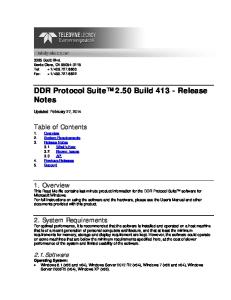
107/111
Estimate of Server Capacity 4X capacity Reduction with CPM
2X capacity
Reduction with multicast OR P2P
Multicast OR P2P: factor of 2 improvement over unicast Multicast AND P2P: factor of 4 improvement over unicast
Page 118
Sensitivity to Peer Upload Bandwidth
Even when the upload bandwidth is constrained, CPM works well
Page 119
108/111
Sensitivity to Popularity of Content
109/111
unicast
P2P multicast + P2P makes CPM less sensitive Using multicast to popularity changes
CPM
Page 120
Summary •
Video viewing will increasingly be “on demand” –
•
Need delivery techniques that scale to a large user base
Propose CPM for serving on-demand video Unified solution that satisfies VoD requirements – Dynamically identifies best delivery mechanism – Exploits the strengths of multicast, P2P, and unicast
–
•
CPM has substantial benefits For users: – Good viewing experience even under high system load – For service providers: – reduces server and bandwidth resource requirements
–
Page 121
110/111
Summary
111/111
We have successfully deployed an end-end IPTV service based on the Internet Protocol Suite We needed to carefully manage several aspects of the architecture and protocol
Network Design
Failure Recovery
Enhance UDP to recover from packet loss
Careful network management to anticipate problems
Scale is still a challenge •
Handling Channel Change – migrate to an all-multicast?
•
Handling VoD – CPM is a reasonable solution
Page 122