County: Any
Hwy: Any
CSJ: Any
Design: BRG
Date: 05/2010
Ck Dsn: BRG
Date: 05/2010
Bearing Pad Design Example Design example is in accordance with the AASHTO LRFD Bridge Design Specifications, 5th Ed. (2010) as prescribed by TxDOT Bridge Design Manual - LRFD (May 2009). The usual starting place for "designing" elastomeric bearings is an analysis of the standard pad configurations for applicability to the superstructure geometry. In particular, the pads must satisfy slip and shear requirements for the designed unit length. Other factors such as compressive stress, deflection, stability, rotation, and bearing seat geometry are typically accounted for in the standard pad design. When using a standard bridge with standard bearing pads it is only necessary to perform the slip check and the shear check. The intention of the original design for the bearing pads represented on the IBEB & IGEB Standard sheets was to make the pads usable for all simple spans, all two span units, and a large number of three span units. Due to all the conditions that can reduce the dead load on the end bearings (narrow beam spacing, short end span, severe beam slope) and thereby increase the chance for slip, good engineering judgment dictates checking the standard pad for suitability on any continuous unit with three or more spans. For purposes of illustrating TxDOT's design method, the example below will examine all the requirements. A standard pad will typically pass the shear check if the unit is less than 400' in length, and it will typically pass the slip check if the unit is less than 3 times the length of the smallest span. In general, designers should be more conservative on stability (both construction and final) and slip, and liberal on compressive allowable stresses.
Unit Information: (3-Span Prestressed Concrete I-Girder Unit) This design example will check the standard bearing pad for the Tx40 Girder. The bridge has prestressed concrete girders (Tx40), T551 rails, and a 30 degree skew. Slip will be checked for the shortest span (60ft), and all other checks will be preformed for the longest span (70 ft). "AASHTO LRFD" refers to the AASHTO LRFD Bridge Design Specification, 5th Ed. (2010) "BDM-LRFD" refers to the TxDOT Bridge Design Manual - LRFD (May 2009) "TxSP" refers to TxDOT guidance, recommendations, and standard practice.
Nspan = Number of Spans in the unit
Nspan
3
Lunit
190 ft
Lunit = Total Length of the Unit Lunit
60 ft � 70 ft � 60 ft
Wbridge = Width of the Bridge
Bearing Pad Design Example
Wbridge
1
46 ft
May 2010
Unit Information: (Con't) ts = Thickness of Bridge Slab
ts
wc = Unit Weight of Concrete for Loads
wc
wOlay = Unit Weight of Overlay
wOlay
Wtgirder = Weight of Girder
Wtgirder
Wtrail = Weight of Rail
Wtrail
Ngirder = Number of Girders in Span
Ngirder
Gr = Max Beam Slope From RDS
Gr
Skew = Bridge Skew
8 in 0.150 kcf 0.140 kcf 0.697 0.382
klf rail
6
0.0093
Skew
klf beam
ft ft
30 deg
Although the skew is shown in this design example and would affect the pad area, it is not used in any of the below calculations since the area reduction of no more than 10%, due to clipped pads, is not a concern. For further explanation see Appendix A on pg. 11.
Bearing Pad Information:
(IGEB Standard)
Check Standard Pad for Ty Tx40 Beam The minimum overall thickness for a bearing pad should be at least 1 1/2" of elastomer (i.e., excluding plate thickness) to help the bearing compensate for beam and bearing seat build-up non parallelism, and/or surface irregularities. Certain cases where the designer needs to accommodate tight construction clearance limitations, match existing profile grades using existing caps, etc., may also be sufficient reason to violate this general rule of thumb for minimum elastomer thickness. Elastomer = 50 Durometer Neoprene hro = Thickness of individual outer (top and
h ro
0.25 in
n ro
2
h rto
0.5 in
h ri
0.25 in
n ri
6
h rti
1.5 in
bottom) layers of elastomer nro = Number of the outer layers of elastomer
50 Durometer Neoprene is standard, but for beams on a severe grade and horizontal displacement 60 or 70 Durometer Neoprene may be desired. For additional information see report 1304-3.
hrto = Total thickness of the outer layers of elastomer h rto
h ro n ro
hri = Thickness of individual interior layers of elastomer nri = Number of the interior layers of elastomer hrti = Total thickness of the interior layers of elastomer h rti
h ri n ri
Bearing Pad Design Example
2
May 2010
Bearing Pad Information: (Con't) hrt = Total thickness of the layers of elastomer h rto � h rti
h rt
2 in
hs
0.105 in
ns = Number of steel layers
ns
7
Fy = Yield Strength of steel layers
Fy
36 ksi
h rt
hs = Thickness of individual layers of reinforcement; 12 gauge steel plates;
h = Total Bearing Pad Height h rt � n s h s
h
h
L = Length of the bearing pad, perpendicular to bridge long axis
L
W = Width of the bearing pad, parallel to bridge long axis
W
2.735 in Refer to Appendix B on pg. 15, Table B-2 or IGEB Standard for bearing pad size.
8 in 21 in
For additional information on tapers, overall geometry and general information see Appendix A starting on pg. 11.
Shape Factor:
(AASHTO LRFD 14.7.5.1)
A = Plan Area of the Bearing Pad L W
A
A
2
168 in
Abi = Area of perimeter free to bulge for an individual interior layer of elastomer Abi
2 ( L � W) h ri
Abi
2
14.5 in
Si = Shape factor for an individual interior layer of elastomer Si
A
Si
Abi
11.586
The target shape factor range is 10.0 to 12.0 (TxSP), to utilize the compressive capacity. If the shape factor is below 10.0 the capacity decreases, and if the shape factor is above 12.0 it does not supply any extra capacity due to the 1.2 ksi cap on the compressive capacity.
Shear Modulus: G73
95 psi
at 73o F
G0
175 psi
at 0o F
(BDM-LRFD Ch 5, Sect. 2, "Materials")
There is a range of values for the shear modulus (95-130 psi) that you may actually receive from the fabricator when you specify 50 Durometer. After the research for Report 1304-3, TxDOT decided to use Yura's suggested value of 95 psi since it is conservative.
Bearing Pad Design Example
3
May 2010
Stability Check:
(AASHTO LRFD 14.7.6.3.6)
hrtMax = Maximum Allowable Total Elastomer Height hrtMax is the smaller of: L 3
2.667 in
3
7 in
2.667 in
h rtMax h rt
W
&
Use hrt instead of the total pad height (BDS-LRFD, Ch. 5, Sect. 2, "Design Criteria").
2 in
(calculated on pg. 3)
hrtMax is greater than h rt therefore OK.
Shear Check:
(AASHTO LRFD 14.7.6.3.4) �6
6 u 10
in
� = Coefficient of Thermal Expansion
α
�T = Temerature range for design
ΔT
70 degF
Use 70 degrees as the Design Tempreture Range (BDM-LRFD, Ch. 5, Sect. 2, "Structural Analysis") For bridges in the panhandle region use 105 degrees.
Δsx
0.537 in
Δsy
0.116 in
Expanding length of prestressed concrete beam units can be taken as 1/2 total unit length. For highly skewed bridges and very wide bridges, take expanding length on a diagonal between slab corners to obtain the most unfavorable expansion length (TxSP).
in degF
�sx = max. total shear deformation of the elastomer at service limit state in the longitudinal direction of the bridge Δsx
α
Lunit � Wbridge sin( Skew) 2
ΔT
�sy = max. total shear deformation of the elastomer at service limit state in the transverse direction of the bridge Δsy
α
Wbridge 2
70 degF
(AASHTO LRFD 5.4.2.2)
�s = max. total shear deformation of the elastomer at service limit state Δs
2
Δsx � Δsy
2
Δs
0.549 in
Current AASHTO specifications suggest a 50% maximum shear strain limit. Therefore, the pad elastomer material (steel plate thickness not included) total thickness must be twice the expected thermal movement at the bearing. hrtMin = Minimum Allowable Total Elastomer Height h rtMin h rt
2Δs
h rtMin
2 in
1.098 in (calculated on pg. 3)
hrt is greater than h rtMin therefore OK.
Bearing Pad Design Example
4
May 2010
Loads (Short Span): Span
60 ft
t Olay
0 in
Thickness of Overlay
Dead Load: BeamDL
Wtgirder
Span
BeamDL
2
20.91 kip
SlabDL
Wbridge Span wc ts Ngirder 2
SlabDL
23.00 kip
RailDL
2 rails Wtrail Span 2 Ngirder
RailDL
3.82 kip
DL
BeamDL � SlabDL � RailDL
DL
Bearing Pad Slip Check: (Service Limit)
There is no overlay on the bridge. The 2" future overlay is not considered since the lightest dead load is conservative for the slip check.
Distribute rail load to all beams for the lightest load.
47.73 kip
(BDM-LRFD Ch. 5, Sect. 2, "Design Criteria")
Use the shear modulus "G 0 " (modulus at 0 deg F) for the slip check because the pad is stiffer at colder temperatures and therefore produces larger shear forces when the beam contracts thermally. �sMax = Maximum Allowable total shear deformation of the elastomer at service limit state ΔsMax Δs
( 0.2 � Gr) u DL u h rt
ΔsMax
G0 u A
0.549 in
0.619 in (calculated on pg. 4)
�sMax is greater tha n �s therefore OK. If the shear check or the slip check were to fail, break up the unit into smaller pieces to avoid needing a non-standard pad. If you are already committed to a non-standard pad design, try increasing the pad height. For more solutions for slip check failure refer to Appendix A on pg.12.
Bearing Pad Design Example
5
May 2010
Loads (Long Span): Span
70 ft
t Olay
2 in
Thickness of Overlay
Dead Load: Wtgirder
BeamDL
Span
BeamDL
2
24.39 kip
SlabDL
Wbridge Span wc ts Ngirder 2
SlabDL
26.83 kip
OlayDL
Wbridge Span wOlay t Olay Ngirder 2
OlayDL
6.26 kip
RailDL
Wtrail
RailDL
4.46 kip
Span 2
1 3 beams
BeamDL � SlabDL � OlayDL � RailDL
DL
DL
61.95 kip
The 2" future overlay is considered in the remaining bearing pad design checks, since the greatest load will control these checks.
Distribute rail load to a maximum of 3 outer beams (BDM-LRFD Ch. 3, Sect. 5, "Structural Analysis").
Live Load: 32 kip � 32 kip §¨
RxTruck
©
62.40
RxTruck RxLane
0.64
LLDF Shear
Span � 14 ft · Span
§ Span � 28 ft · ¸ � 8 kip ¨ Span ¸ ¹ © ¹
kip lane
klf Span 2
RxLane
lane
22.40
kip
(AASHTO LRFD 3.6.1.2.4)
lane
0.895 (AASHTO LRFD Table 3.6.2.1-1)
IM
33 %
LL
ª¬RxTruck ( 1 � IM) � RxLaneº¼ LLDFShear
LL
94.33 kip
σd
0.369 ksi
σL
0.561 ksi
σs
0.93 ksi
Stresses: Dead Load Stress: σd
(AASHTO LRFD 3.6.1.2.2)
DL A
The Live Load Reactions are assumed to be the Shear Live Load Distribution Factor multiplied by the Lane Load Reaction. The Shear Live Load Distribution Factor was calculated using the "LRFD Live Load Distribution Factors" Spreadsheet
Live Load Stress: σL
LL A
Total Load Stress at Service: σs
LL � DL A
Bearing Pad Design Example
6
May 2010
Compressive Stress Check: (Service Limit) Si
(BDM-LRFD Ch. 5, Sect. 2, "Design Criteria") (Calculated on pg. 3)
11.586
�dMax = Maximum Allowable Dead Load Stress �dMax is the smaller of:
The 1200 psi dead load stress maximum should not be exceeded by more than 5%, and only if the shape factor permits. For further explanation see Appendix A on pg. 13.
1.2 ksi 1.2 G73 Si σdMax σd
1.321 ksi
1.2 ksi
0.369 ksi
(Calculated on pg. 6)
�dMax is greater than � d therefore OK. �sMax = Maximum Allowable Service Load Stress �sMax is the smaller of:
The 1500 psi limit, is not an absolute max, and overages of up to 15% above this limit are not cause to resize the pad. For further explanation see Appendix A on pg. 13.
1.5 ksi 1.5 G73 Si σsMax σs
1.651 ksi
1.5 ksi
0.930 ksi
(Calculated on pg. 6)
�sMax is greater than � s therefore OK.
Compressive Deflection: (Service Limit)
(AASHTO LRFD 14.7.6.3.3)
Compressive deflection is usually not a concern from a functionality standpoint since the 4% to 5% range of deflection that most of TxDOT's standard pads undergo, yields a hardly noticeable 3/32" vertical compression. For further explanation refer to Appendix A on pg.13. Estimate compressive deflection using AASHTO LRFD Fig. C14.7.6.3.3-1.
(BDM-LRFD, Ch. 5, Sect. 2, "Design Criteria")
σs
0.930 ksi
(Calculated on pg. 6)
Si
11.59
(Calculated on pg. 3) Use S i and Vs to get Hsi from Figure C14.7.6.3.3-1, which can be found in Appendix C on pg.16, Figure C-1.
(AASHTO LRFD Fig. C14.7.6.3.3-1) ε si
�si = Elastomer Strain for Service Loading Bearing Pad Design Example
7
3.8 % May 2010
Compressive Deflection: (Con't) �di = Elastomer Strain for Dead Load ε di
ε si
σd σs
ε di
1.506 %
ε Li
2.294 %
�Li = Elastomer Strain for Live Load ε Li
ε si
σL σs
Since all layers in the bearing pad are the same thickness and shape, Hi is the same for every layer and therefore the below equations are true. �di = Instantaneous Dead Load Compression Deflection of Elastomer δd
ε di h rt
� cr = Creep Deflection Factor
δd
0.030 in
(AASHTO LRFD Eq. 14.7.5.3.6-2)
αcr
0.25
(AASHTO LRFD Table 14.7.6.2-1)
δlt
0.038 in
(AASHTO LRFD Eq. 14.7.5.3.6-3)
δL
0.046 in
(AASHTO LRFD Eq. 14.7.5.3.6-1)
δs
0.084 in
�lt = Long Term Compression Deflection of Elastomer δlt
δd � αcr δd
�L = Instantaneous Live Load Compression Deflection of Elastomer δL
ε Li h rt
�s = Service Load Compression Deflection of Elastomer δs
δlt � δL
�siMax = Maximum Allowable Service Load Compression Deflection of an Interior Layer δsiMax
δsiMax
0.07 h ri
0.018 in
(AASHTO LRFD 14.7.6.3.3)
�si = Service Load Compression Deflection of an Interior Layer δsi
h ri δs h rt
δsi
0.010 in
�siMax is greater tha n � si therefore OK.
Bearing Pad Design Example
8
May 2010
Rotation: (Service Limit)
(BDM-LRFD Ch. 5, Sect. 2, "Design Criteria")
AASHTO has strict guidelines for rotation that TxDOT does not adhere to. AASHTO seeks to prevent any amount of lift off, a requirement that TxDOT does not support. Most TxDOT reinforced elastomeric bearing pads are used under prestressed concrete beams that rotate little (less than 0.005 radians) and impart a fairly heavy dead load on a relatively narrow (9" max) pad, making uplift due to rotation an improbable event. The research for Report 1304-3 has shown rotations close to 0.030 radians can be accommodated by our standard pads with less than 20% lift off, and even with that amount of lift off the pad will function normally. We regularly encounter cases in construction where it is noted that the pad is not in contact with a bearing surface for a considerable portion of the pad area (usually due to construction tolerances, mismatches in surface slopes, etc.) with no apparent detriment to the bearing performance in final service. Non-Composite I-Beam Properties: E = Modulus of Elasticity of the Beam
E
5000 ksi
Ix = Non-Composite Moment of Inertia of
Ix
134990 in
4
the Beam about its strong axis q = Total Dead Load of the Superstructure per foot of the beam q
DL
q
Span y 2
The load due to the Rail and Overlay act on the Composite Cross-Section of the Beam. For simplicity, we will apply all the dead load to the Non-Composite Cross-Section. The Moment of Inertia of the Tx40 girder can be found on the IGD standard.
1.77 klf
�DL = Rotation due to Dead Load θDL camber
q Span
3
24 E Ix
§¨
12 in ·
2
θDL
¸ © ft ¹
0.005 rad Use the Camber from PSTRS14 output or PGSuper output
3.552 in
�Camber = Rotation due to Camber θcamber
4 camber Span
y
§ 12 in · ¨ ft ¸ © ¹
θcamber
0.017 rad
�LL = Midspan Deflection due to Live Load ΔLL
Span 800
§¨
12 in ·
¸ © ft ¹
ΔLL
1.05 in
θLL
0.005 rad
�LL = Rotation due to Live Load θLL
4 ΔLL Span
y
§ 12 in · ¨ ft ¸ © ¹
Bearing Pad Design Example
9
Assuming camber is the result of uniform moment caused by prestressing
Use the LL Midspan deflection from PSTRS14/PGSuper or use the design deflection limit, Span/800, to be conservative. (BDM LRFD Ch. 5, Sect. 2, "Design Criteria")
May 2010
Rotation: (Con't) Rotation due to Downward Deflection of Girder: Tcamber is greater than TDL therefore: θDL_camber
�DL_camber = Rotation due to Dead Load
0 rad
and Camber in the direction of rotation caused by downward applied forces � = Rotation due to maximum downward deflections of beam θ
θLL � θDL_camber � 0.005 rad
θ
0.010 rad
�sMin = Minimum Allowable Service Load
When checking rotations due to downward deflections, the rotation from the combined effects of camber and dead load will not be taken less than zero. This is done to be conservative and because camber is highly variable. 0.005 radians is added to account for construction uncertainties (AASHTO LRFD 14.4.2.1)
Compression Deflection θ ( 0.8 L)
δsMin δs
δsMin
2
0.032 in
0.084 in
(BDM LRFD Ch. 5, Sect. 2, "Design Criteria") (Calculated on pg. 8)
��s is greater than �sMin therefore OK. Rotation due to Upward Deflection of Girder: � = Rotation due to maximum upward deflections of beam θ
θcamber � θDL � 0.005 rad
θ
0.017 rad
�sMin = Minimum Allowable Service Load
0.005 radians is added to account for construction uncertainties (AASHTO LRFD 14.4.2.1)
Compression Deflection θ ( 0.8 L)
δsMin δs
δsMin
2
0.053 in
0.084 in
(BDM LRFD Ch. 5, Sect. 2, "Design Criteria") (Calculated on pg. 8)
��s is greater than �sMin therefore OK.
Reinforcement Check: (Service Limit) hs
(AASHTO LRFD 14.7.6.3.7)
0.105 in
(From pg. 3)
hsMin = Minimum Allowable Steel Layer Thickness 3 h ri σs
h sMin
h sMin
Fy
0.019 in
(AASHTO LRFD Eq. 14.7.5.3.5-1)
hsMin is smaller than h s therefore OK. ΔFTH
�F TH = Constant Amplitude Fatigue
24 ksi
Threshold h sMin
2 h ri σL
h sMin
ΔFTH
0.012 in
(LRFD AASHTO Table 6.6.1.2.5-3, Category A) (AASHTO LRFD Eq. 14.7.5.3.5-2)
hsMin is smaller than h s therefore OK. Bearing Pad Design Example
10
May 2010
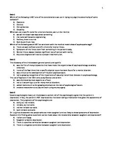
Appendix A Unit Information: Skew: In general, the clipped pad areas do not decrease by more than approximately 10%. The pad plan dimensions were increased when more severe clips were needed. The 10% reduction for clips or the area for dowel holes is not a concern for the following reasons: 1.) Reducing the area of the pad increases the DL stress, thus increasing slip prevention. 2.) The standard bearing pad is typically conservative with regard to allowable compressive stresses. 3.) Shape factor controlled allowable DL compressive stresses vary minimally from the assumptions in the standards due to the altered perimeter to area ratios when clipped. 4.) Compressive deflections are usually around 3/32" for standard pads. Bearing Pad Information: Bearing Pad Taper: Taper is usually not specified by the designer for TxDOT jobs. The fabricators typically extract this information from the contract plans by calculating the beam slope from bearing seat elevations on the bridge "Bearing Seat Elevations and Quantities" sheet. The fabricator then determines which platen satisfies the slope tolerance specifications and can be used in the pad vulcanization process. The standard pads listed on the IBEB sheet will deflect around 4% on average, or about 5/32" for the 2" of elastomer in them, which typically is sufficient to accommodate a slope mismatch from fabrication or construction sources. (5/32" in 9" is equivalent to a slope of 1.74%.) Design Recommendations: 1.) For beams on grades of between 1 and 3%, taper the pads accordingly. The top layer only shall be tapered. (all shims parallel) 2.) For beams on grades of between 3 and 6%, taper the top two layers, limiting the top layer thickness to 3/8" at the thick end. (all shims parallel except top shim) 3.) Beams on grades greater than 6% will require special consideration (ie, span restraints, pad restraints, higher durometer elastomer, custom shim placement, etc.; see Report 1304-3, Chapter 8 for conclusions concerning heavily tapered pads). 6% beam slope is the upper limit that TxDOT will design tapered pads for without special precautions, such as locking the "low" end of the unit in place and forcing the structure to expand uphill. Bearing Seat Geometry: For custom applications, the designer needs to be aware of the specified minimum cap edge and beam edge distances. The centerline of bearing is a nominal distance and the pads will function satisfactorily if placed off center from it as long as the load is not placed close to a cap edge (which will induce spalling of the cap) or overlapping a beam chamfer edge (which will pinch the elastomer and induce a "walking" phenomena on the cap surface). When checking the required edge distances for custom designs, also take note of the beam end clearance values listed on the standard. Beam end clearance values vary with cap type and are increased on cap types such as inverted tee interior bents, where field experience with construction/fabrication errors and resulting beam end trimming has dictated the need for more room.
Bearing Pad Design Example
11
May 2010
General: Continue to "round" layer thicknesses to 1/8" increments within shape factor constraints. Pad width (transverse to beam longitudinal axis) for custom designs should not be less than approximately 3/4 of the bottom beam flange width without a more thorough analysis. TxDOT currently has some exceptions to this guideline - round pads, pads for smaller beams, etc - but have had feedback that in general there have been no construction related stability problems with these particular pads. A general rule of thumb is to design the width of the pad so that the c.g. will always fall within the middle third of the pad. If construction tolerances, i.e. horizontal beam sweep, variance from plumb, out of level bearing seats and so on, can vary the c.g. 4", then the pad should be at least 12" wide. Bearing Pad Material: TxDOT currently prohibits the use of "Polyisoprene" (Natural Rubber) for the manufacture of bearing pads. This is due to a slip problem experienced in the late 1980's and early 1990's that was caused by a "blooming" of paraffin wax to the surface of the pad. This wax can be used in "Polychloroprene" (Neoprene) but is usually present in much smaller amounts than in natural rubber, and as yet there have been no documented cases of neoprene-associated slip due to a wax bloom in Texas. Bearing Pad Slip Check: Bearing Pad Slip Failure Fixes: Typically slip problems are controlled by increasing the pad thickness. In some cases this may not be desirable from an economic standpoint (fabricator re-tooling) or if the resulting height violates stability criteria. Alternative solutions might include the following: 1) Increase the beam spacing to increase bearing dead load, if the beams can handle the additional load. 2) Increase the end span length if feasible, to increase the compressive stress. The span length should not be increased to the point of requiring an additional beam line. This may not be possible if there are conflicts such as lower roadways, utilities, waterways, etc. 3) Reducing the number of spans in the unit. This is the best choice for standard bridges, as it does not require modified drawings or an in-depth bridge design. For a non-standard bridge, only choose this option if the resulting increase in cost of deck joints does not offset the cost of custom pads. (Standard pads cost approximately $65 to $100 each (FY 2006), custom pads cost almost double the amount of standard ones. Both items usually represent a very small percentage of overall bridge cost and therefore, the decision on which item to purchase is not critical.) 4) As a last resort, decrease the pad plan area to increase slip resistance. The least expensive way to do this is to pick a standard pad from any of our bearing pad standards (IBEB, IGEB, SBEB, BBEB, UBEB, PSBEB, DSBEB, DTBEB). The standard bearing pads are four standard heights (2 3/4" {IBEB, IGEB, SBEB, BBEB}, 2 1/2" {UBEB}, 2" {PSBEB, DSBEB}, and 1 1/4" {DTBEB}); try using a bearing pad that is the same height or taller to satisfy slip. For a Type "Tx40" beam (standard pad: 9" L x 21" W x 2 3/4" h) that fails in slip, try the "IV" pad from the IBEB table (standard pad: 7" L x 22" W x 2 3/4" h). If none of the standard pads solve the problem, design new pad plan dimensions. This requires the fabricator to order new forms or shim for the insides of existing forms, so a large volume job is preferable for this option. When reducing the plan area, do so by decreasing the pad length to preserve pad stability. Construction stability of the beam on the bearing prior to construction bracing installation may be a concern when calculating the pad length reduction. There have been no reports of construction instability associated with relatively narrow pad widths such as that for an AASHTO Type IV beam when using the 15" diameter round pad. Another rule of thumb is to make the pad wide enough so that the center of gravity will never fall outside of the middle third of the pad. This calculation would be based on the designer's estimate of how out of plumb the beam may tilt in the field due to bearing seat construction tolerances, beam fabrication tolerances, beam "warping", etc. In the absence of a more refined approach, the use of existing pad geometries is probably the best solution. Bearing Pad Design Example
12
May 2010
Compressive Stress Check: Allowable Compressive Stresses: The Service Load check is intended to keep the maximum stresses within a reasonable "range"; it is believed that the temporary nature of a live load has little effect on long term serviceability of the bearing. Thus, the 1500 psi limit, is not an absolute max and overages of up to 15% above this limit are not cause to resize the pad. Reinforced elastomeric bearing pads in the configurations that TxDOT uses have failed in laboratory compression tests at stresses of between 15,000 and 20,000 psi and therefore have large factors of safety against compressive failure. Of greater concern is the loading that the pad sees on a permanent basis, such as under dead load, the consequent side face bulging, and how well the pad functions in combination with cycles of thermally-induced shear strain. For this reason the 1200 psi dead load stress maximum should not be exceeded by more than 5% and only if the shape factor permits. Unlike AASHTO requirements for Method A or Method B, TxDOT design practice places no additional requirement on materials testing when using these allowable compressive stresses. Instead, material quality is insured via prequalification of fabricators, the elastomer formulation and 100% load testing of pads produced for TxDOT. Compressive Deflection: Compressive Deflection: Compressive deflection is usually not a concern from a functionality standpoint, since the 4% to 5% range of deflection that most TxDOT standard pads undergo yields a hardly noticeable 3/32" vertical compression. Severely tapered pads can deflect up to 60% more (close to 5/32" total), but still not enough to induce a "bump" at the end of a bridge. This information becomes useful when determining if a pad can absorb construction mismatches and/or to check rotation ability. Creep will add as much as 25% more deflection, but this is not a concern as it will add a maximum 3/16" total deflection.
Bearing Pad Design Example
13
May 2010
Appendix B
Table B-1. Elastomeric Bearing Data from the IBEB Standard
Bearing Pad Design Example
14
May 2010
Table B-2. Elastomeric Bearing Data from the IGEB Standard
Figure B-1. Bearing Pad Plan Dimentions from the IGEB and IBIB Standards
Bearing Pad Design Example
15
May 2010
Appendix C
Figure C-1. Stress-Strain Curves from AASHTO LRFD Fig. C14.7.6.3.3-1
Bearing Pad Design Example
16
May 2010